

Page 1
p
)
141 Rodeo Drive tii 78 / 79 Series
Edgewood, NY 11717 Dual Service Provider Switch
Customer Service/Sales 888-844-4720 02/08 Rev B
INSTALLATION NOTE
1. GENERAL DESCRIPTION
1.1 The TII 78 and 79 Series are designed for
applications requiring more than one service provider
which requires a connection to a single tip-ring pair. It
offers one or more outputs for the customer premises
telephone wire termination.
2. WARRANTY
2.1 See TII Warranty. If this unit fails during the
warranty period, the factory should be requested to
authorize return. Return the unit prepaid. Units that fail
due to normal wear or abuse should be discarded.
3. INSTALLATION
3.1 Remove the Dual Service Provider Switch
from plastic bag and inspect; if damaged, replace with
an undamaged switch.
3.2 Installation is accomplished using standard
technician tools. The Insulation Displacement
Contacts (IDC) are achieved using gel sealed
rockers.
3.3 IDC Terminations accept 26-22 AWG solid wire.
3.4 Locate a suitable flat, dry area to install the unit.
Use a size #8 screw to mount the unit. Install the TII
78 Series Termination Block. See Figure 1.
3.5 The 78 switch can be installed within an indoor /
outdoor listed housing. Use suitable hardware to
attach the block to the mounting service.
3.6 The 79 switch mounts in the customer
compartment of a TII 5100 NID. See Figure 2.
3.7 Lower the 79 switch into the 5100 NID and align
the locating fingers with the locating slots. Press down
until unit locks into locking tab. See Figure 3.
4. WIRING
4.1 Provides three pair customer wire terminations
with very low insertion loss from input to output.
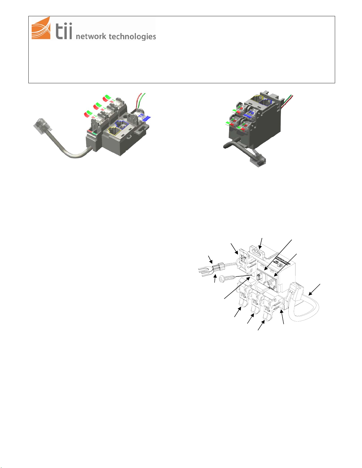
TII 78
TII 79
Do not strip wire insulation from wires to be
terminated to Switch.
TII 78 Wiring
Tip (Green)
Digital Voice
Service In
ut
Wire Loom
MTA Input
3 Pair Telco Input
Ring (Red
RJ-11 Interface
Mounting Hole
Customer Wire Telco
Output Terminations
Test Points
FIGURE 1
NOTE: IDC’s accept 22-26 AWG solid wire. Wires
should be aligned to the corresponding holes.
Green wire to the “T” (GRN) labeled wire guide
and the Red wire to the “R” (RED) labeled wire
guide.
TII P/N 92225101
Page 2
p
Telco Service
4.2 Wire spaded lugs to the corresponding Telco
Service Input.
4.3 Insert the RJ-11 interface plug into the 3 pair
Telco input receptacle.
4.4 Insert wires into customer wire guides at the
same time until they bottom out. While holding
wires in wire guides, terminate rocker with thumb
(lower rocker all the way).
4.5 Terminate additional wire pairs to the remaining
rockers as required.
VoIP Service
4.6 Connect the Digital Voice Service Input wires to
the Blue MTA rocker, following step 4.4.
4.7 Insert the RJ-11 interface plug into the MTA input
receptacle.
4.8 Insert wires into the customer wire telco output
rockers as required.
5. TESTING
5.1 Test for line continuity using the test points. (Figure
1).
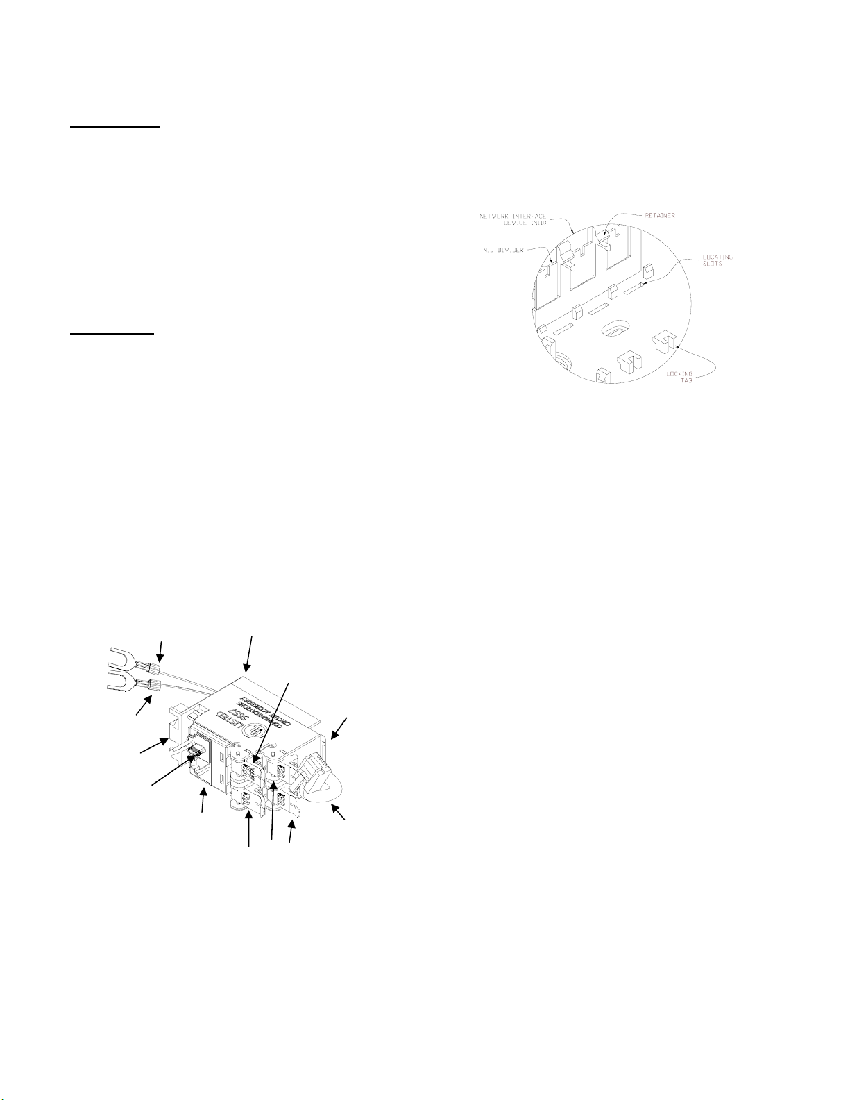
TII 79 Installation
FIGURE 3
Tip (Green)
Test Points
Ring (Red)
MTA Input
3 Pair Telco Input
TII 79 Wiring
Locating Fingers
Customer Wire Telco
Output Terminations
FIGURE 2
Digital Voice
Service In
Locking Hinge
RJ-11 Interface
ut
TII P/N 92225101
 Loading...