

Page 1
P/N 92233301 • Rev D • ECN 11-269 • 11/14/2011
Warranty: If this unit fails during the warranty period, contact tii customer service to authorize return. Unit may be returned prepaid.
Model 761-4T-12, 761-4T-12K
Double Wall Plate
DSL POTS Splitter for
VDSL2/ADSL2+/IPTV Services
Installation Note
Description
TELCO
WIRING
RED WIRE
GREEN WIRE
PREMISES
WIRING
EXISTING
JUNCTION
BOX
MOUNTING
HOLES
RJ-11 JACKS
CENTRAL
OFFICE
INPUT
CUSTOMER
INPUT
DATA
INPUT
IDC ROCKERS
Installation
1. The tii 761-4T-12, 761-4T-12K Double Wall
Plate is an indoor telephone surface mount
phone jack with two RJ-11 jacks and three
IDC rockers.
2. The tii 761-4T-12, 761-4T-12K utilizes gel
sealed insulation displacement terminations
(IDC) that provide reliable connectivity.
3. The tii 761-4T-12, 761-4T-12K is for indoor
use only.
4. IDC rockers are used to terminate 26-22AWG
solid wire.
1. The tii 761-4T-12, 761-4T-12K should be
mounted to a standard single gang electrical
wall box.
2. Locate the existing phone jack outlet box
where telephone wires enter the premises.
Disconnect the incoming telephone service to
the existing RJ-11.
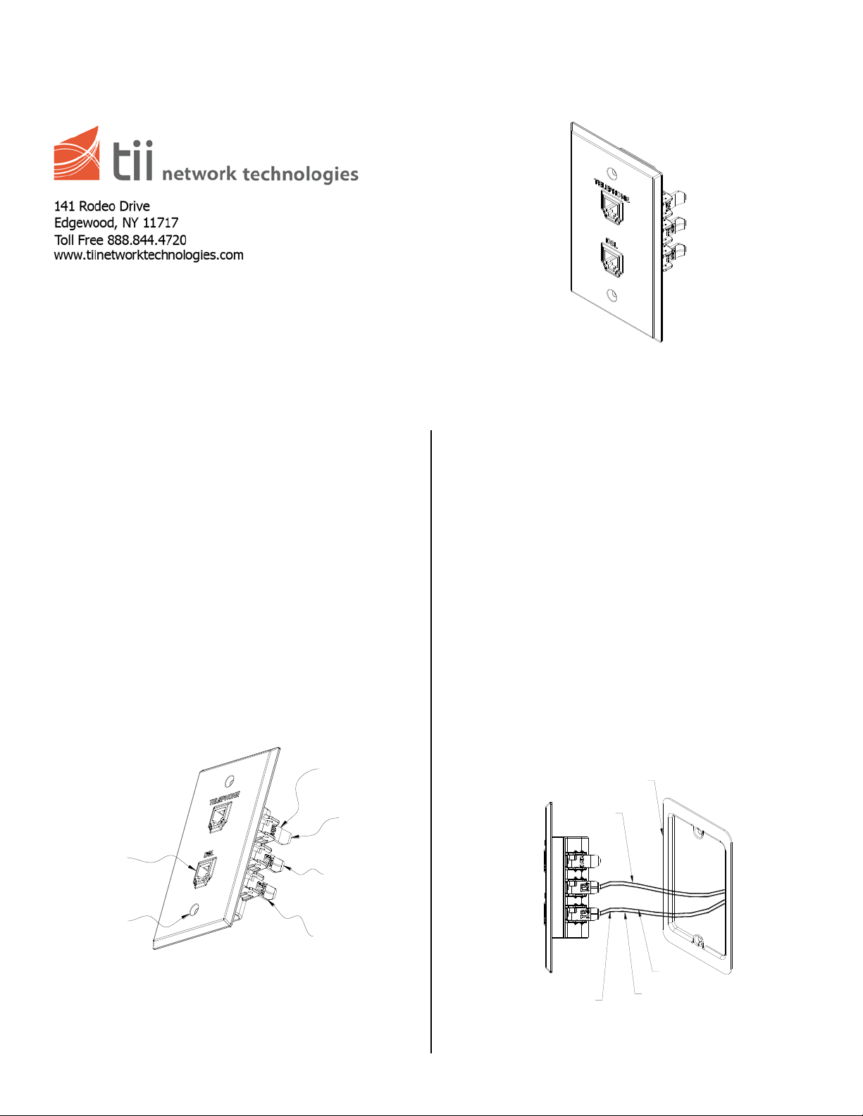
3. Turn the 761-4T-12, 761-4T-12K so the IDC
rocker is facing you (See Figure 2).
4. Pull up the bottom IDC rocker to the fully open
position, insert Telco wires as shown in Figure
2 until they bottom out, do not strip wires.
Features
5. Insert premises wiring to the middle IDC as
shown in Figure 2.
6. Push down the IDC rocker to the closed
position for termination.
Figure 1
Figure 2
Page 2
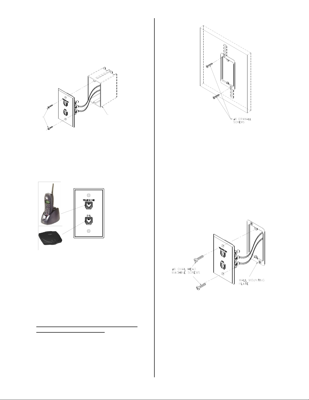
7. Dress the wires properly inside the junction
#6 OVAL HEAD
MACHINE SCREWS
EXISTING JUNCTION
BOX
box and secure the 761-4T-12, 761-4T-12K to
the junction box using the supplied #6 oval
head screws (See Figure 3).
The 761-4T-12K also includes (2) #6 x 2” lg.
oval head screws with ferrules.
Figure 3
Figure 5
8. Connect the existing phone and DSL modem
into their respective RJ-11 receptacles on the
front face plate (See Figure 4).
Figure 4
Existing Construction Installation
1. Cut drywall 2” W x 3.5” L in the location where
the 761-4T-12, 761-4T-12K will be mounted.
Prior to cutting hole confirm that there are
no obstructions behind wall.
3. Dress the wires properly inside the wall
mounting plate and secure the 761-4T-12,
761-4T-12K to the wall mounting plate using
the supplied #6 oval head screws
(See Figure 6).
The 761-4T-12K also includes (2) #6 x 2” lg.
oval head screws with ferrules.
Figure 6
2. After drywall has been cut, install a metal cutin ring wall mounting plate, (available
separately from tii). Bend the two mounting
tabs behind the drywall and secure the
mounting plate with the supplied drywall
screws, (See Figure 5). Align the mounting tab
slots while tightening the screws.
 Loading...