

Page 1
tii 759
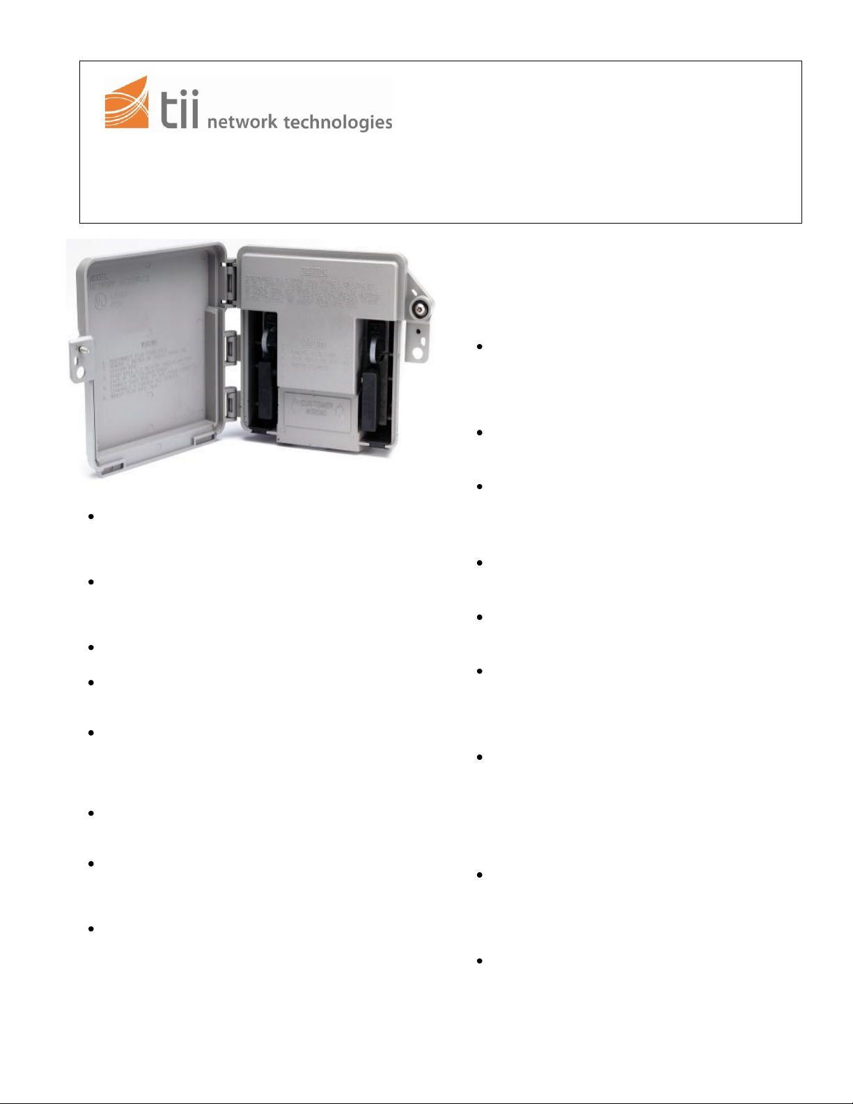
141 Rodeo Drive Universal Network Adapter
Edgewood, NY 11717 1/08 Rev B
Toll Free 888.844.4720
www.tiinettech.com
INSTALLATION NOTE
authorize return. Return the unit prepaid when
authorization is received. Units that fail due to
abuse or normal wear should be discarded.
2. INSTALLATION – PREPARATION
If there are any outboard electronic packages
mounted beside the AT&T 881B station protector,
they may have to be moved. The tii 759 Series
Adapter requires a clear space of three inches on
both sides and top of the station protector.
After ensuring that adequate space is available to
mount the tii 759 Adapter, remove and discard
the 8813B cover.
1. GENERAL
The tii 759 Universal Network Adapter is
designed to retrofit either one pair or two pair
station protector housed in an AT&T 8813B
Service Enclosure.
The tii 759 1 is furnished complete with
customer wiring bridge / RJ-11 modular jack with
spade tipped leads for one pair. The tii 759 2 is
similarly equipped for two pair.
No special tools are required to install or
maintain this product.
The tii 759 is equipped with a cover tab that
allows the customer to lock the unit, but allows
the Telco to override the lock.
The interior has a set of hinged covers that keep
the Telco protector modules and station
electronics out of the customer’s view and touch.
They may be accessed with a 3/
” hex head
8
terminal wrench or a pin-in-head wrench.
The customer wiring bridge and the RJ-11
modular jack are press fit and readily field
replaceable.
The tii 759 Series Universal Network Adapter is
equipped with four card slots which allow a
variety of station electronics to be fitted to the
customer line.
If the hook up wire or OSP cable is physically
larger than No. 22AWG, a fusing conductor of
No. 22AWG solid copper wire with thermoplastic
insulation or No. 22AWG copper clad steel
(bridle wire) shall be employed.
1. WARRANTY
See tii Warranty. If this unit fails during the
warranty period, the factory should be requested to
Inspect the protector, wiring and ground
connection. Perform any maintenance required by
local practice.
3. INSTALLATION – NO ELECTRONICS
Carefully remove the inside wires from the
protector and pull them out through the grommet.
Carefully bend them away from the installation.
Remove the tii 759 Adapter from the box and
inspect if for damage. If the unit is damaged,
obtain another unit.
Using a screwdriver loosen the screw below the
hex head or pin-in-head security screw and open
the outer door. Then with a 3/
” hex head terminal
8
wrench or a pin-in-head wrench, loosen the
security screw and open the inner door.
Place the tii 759 Adapter over the “B” closure
base about one third of the way up and all the
way to the wall. Then slide the tii 759 Adapter
down until you hear the unit snap and lock into
place. The tii 759 is designed to fit snugly over the
base of the AT&T 8813B but does not require
excessive force to install.
Locate the RED and GREEN spade tipped wires
coming from the RJ-11 jack on the right hand side
and terminate them on the Ring and Tip terminals
of the upper protector module respectively.
Observe polarity.
If the tii 759 Adapter is fitted for two lines, and the
second protector module is in place, locate the
RED and GREEN spade tipped wires coming
from the RJ-11 jack on the left hand side.
Terminate them on the ring and tip terminals of
the second protector module. Observe polarity.
tii P/N: 92204701
Page 2

Depending on local practice, the YELLOW
spade tipped wires may be terminated on the
ground post, or taped to prevent electrical
interference and dressed out of the way.
Carefully inspect the work performed for shorts,
crosses, grounds, and polarity. Close the inner
door and secure it by tightening the security
screw.
Remove the plug from the RJ-11 jack. For those
units supplied with protective warning cover(s),
lift the protective warning cover(s) exposing the
customer bridge.
Make a hole in the soft vinyl grommet located
under the right hand customer wiring bridge.
Thread the station wire through the grommet.
Dress the station wires to the right hand side of
the wiring posts, and terminate the RED and
GREEN wires on the two lower wiring posts.
Observe polarity.
If the tii 759 is fitted for two lines and the second
line is to be terminated, follow the instructions in
Paragraph 4.10 using the left hand customer
wiring bridge.
Replace protective warning cover(s) over
customer bridge(s) where provided and reinsert
the plug into the RJ-11 jack, making certain that
it is properly seated, then close the outer door
and secure it by tightening the screw.
4. INSTALLATION – WITH ELECTRONICS
Follow the steps outlined in Section 3.00 for
installation preparation.
If there are existing electronics mounted outside
the station protector, it will be necessary for you
to carefully note how they are wired into the
circuit.
Electronic packages that are mounted outside
the station protector, having terminals for station
wire connection and factory installed cable for
connection at the protector, may be installed as
described in the following sections.
Mount the tii 759 as outlined in paragraphs 4.02,
4.03 and 4.04.
Carefully remove the station wires from the
outboard electronics module.
Place a jumper cable (piece of inside wire) at
least 18” long from the card slot section of the tii
759 Adapter through the protector grommet to
the outboard electronics module.
Terminate the RED, GREEN and YELLOW
wires onto the appropriate terminals of the
electronic module.
Dress the other end carefully around the
protector, and terminate the RED, GREEN and
YELLOW wires onto three of the wiring posts in
the card slot section of the tii 759 Adapter.
Locate the spade tipped leads associated with the
RJ-11 jack to be used, and terminate them on the
wiring posts with the jumper cable. Observe
polarity.
Terminate the customer’s inside wire following the
steps in paragraph 4.09 and 4.12.
5. INSTALLATION – HALF RINGER
If the conversion of the station protector is to
include the installation of a tii 856 Half Ringer, a
card slot for this product is located on the top
section of the tii 759 Adapter.
Open the inner door of the tii 759 Adapter and
observe the four card slots. The two uppermost
slots, designated “A” and “B” are intended for the
tii 856 Half Ringer of the tii 807 Maintenance
Termination Unit.
Slide the tii 856 card into one of the slots, and
connect the RED and GREEN spade tipped leads
to the Ring and Tip terminals of the protector
respectively.
Inspect your work carefully for shorts, crosses,
grounds and polarity.
Close and secure the inner and outer door.
Perform all necessary tests.
6. INSTALLATION – MTU
Open the inner door of the tii 759 Adapter.
Observe the four card slots. The two uppermost
slots designated “A” and “B” are intended for the
tii 856 Half Ringer or the tii 807 Maintenance
Termination Unit.
Select one of these slots and slide the card into
place. Terminate the RED and GREEN spade
tipped leads to the Ring and Tip terminals of the
protector. Observe Polarity.
Connect the YELLOW and BLACK (some units
may use Red with a White tracer instead of
Yellow, and Green with a White tracer instead of
Black) spade tipped leads to two wiring posts in
the card slot section.
Remove the plug from the RJ-11 jack. For those
units supplied with protective warning cover(s), lift
the protective warning cover(s) exposing the
customer bridge. Terminate the RED and GREEN
spade tipped leads from the RJ-11 modular jack
to the two wiring posts with the YELLOW and
BLACK leads respectively. Observe polarity.
Inspect all work for shorts, crosses, grounds and
polarity and then replace protective warning
cover(s) over customer bridge(s) where provided
and reinsert the plug into the RJ-11 jack, making
certain that it is properly seated, then close the
outer door and secure it by tightening the screw.
7. SECURITY
tii P/N: 92204701
Page 3

The tii 759 Network Interface Adapter is furnished
with a locking tab that allows the customer to
padlock the NID if so desired. The tab is also
designed to allow the Telco to override the padlock
through the use of the 3/
wrench, or the optional pin-in-head wrench,
depending on which option is equipped.
” hex head terminal
8
tii P/N: 92204701
 Loading...