

Page 1
P/N 92233501 • Rev B• 11/23/2009
Warranty: If this unit fails during the warranty period, contact tii customer service to authorize return. Unit may be returned prepaid.
Model 751-1T-01
Indoor Baseboard Jack
Installation Note
Description
1. The TII 751-1T-01 is an Indoor Network
demarcation point device suitable for multi
dwelling units. When installed at the service
entry point phone outlet, the unit provides
access to the telephone company’s central
office signals while disconnecting the inside
premises wiring. This is accomplished by
accessing the test jack identified on the front
of each unit. A “full-time” phone jack is also
provided on each unit so that a telephone
connection may be established at the location.
The unit is equipped with a half-ringer test
circuit for remote testing.
2. The TII 751-1T-01 is a surface mount unit
which may be mounted to a wall surface.
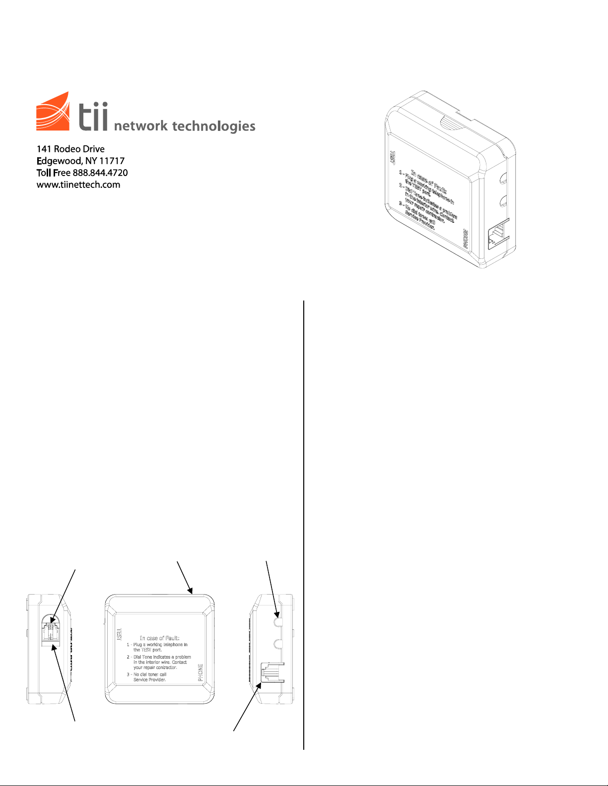
Features
AUTOJACK
REMOVABLE TOP
COVER TO ACCESS
IDC CONNECTIONS
SLIDER
DOOR
RJ11 OUTPUT
CONNECTOR
UNTRIMMED WIRING
EXITING HOLES
Installation
GeneralNotice:
1. Installation of the TII 751-1T-01 must be in
accordance with the local Codes and Article
800 of the National Electric Code, ANSI/NFPA
70.
2. The TII 751-1T-01 is intended for indoor use.
3. In a typical installation the TII 751-1T-01 is
installed ahead of all telephone connections
inside the customer premises. The unit must
be installed at the point of service wire entry.
All customer premises wiring is then fed from
the TII 751-1T-01 Baseboard Jack.
InstallingtheBaseboardJack:
1. Detach the cover from the base by depressing
the finger grips located on both sides of the
cover. Pull the cover away from the base.
2. Identify and isolate the incoming telephone
company wires from the customer premises
wiring.
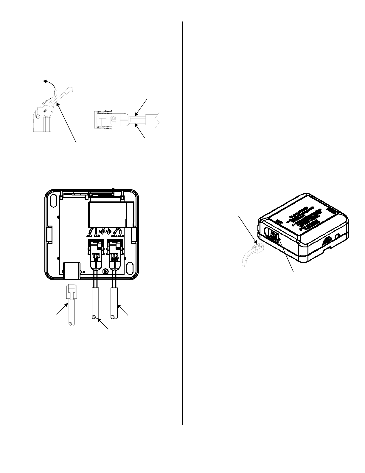
3. Install the tip and ring wires from the
telephone company into the IDC rocker
(marked “IN”). Do not strip the wires. Pull up
the IDC rocker to the fully open position &
insert the Telco wires until they bottom out
(See Figure 1).
4. Push down the IDC rocker to the closed
position for termination. See Figure 2 for the
TII 751-1T-01 wiring.
5. Install the inside customer premises wiring into
the IDC rocker (marked “OUT”). Do not strip
the wires. Pull up the IDC rocker to the fully
open position & insert the customer premise
wires until they bottom out (See Figure 1).
Page 2
6. Push down the IDC rocker to the closed
position for termination. See Figure 2 for the
TII 751-1T-01 wiring.
7. If the customer premise wiring is fitted with an
RJ11 connector (See Figure 2), you may use
the RJ11 jack in place of the IDC (marked
“OUT) as mentioned in step 7.
PULL UP
ROCKER
DO NOT STRIP WIRES
THEN FULLY INSERT
WIRES INTO ROCKER
Figure 1
RED WIRE
(RING)
GREEN WIRE
(TIP)
Central Office Signal Testing
1. Slide open the cover from the Auto-Jack® test
receptacle located on the side of unit. Using a
working telephone, insert the telephone RJ-11
plug into the Auto-Jack (See Figure 3).
2. Wait a few seconds, lift the receiver and listen
for a dial tone.
3. If dial tone is not present, check connection to
the service wires from the telephone company.
Once the connections are verified and dial
tone is still not detected, contact the phone
service provider.
4. If the dial tone is present, then the phone line
service up to the Baseboard Jack is functional.
Remove the telephone plug from the test jack
and close the sliding cover.
5. Check for dial tone on all other telephones
within the premises. If the dial tone is audible,
the proper connections have been made.
RJ11 PLUG FROM GOOD
WORKING TELEPHONE
Figure 3
SLIDING DOOR
OPTIONAL RJII
CUSTOMER WIRING
TO PREMISES
TELCO SERVICE
WIRE CONNECTIONS
CUSTOMER WIRING
TO PREMISES
Figure 2
Final Installation Step
1. Fasten the TII 751-1T-01 to the wall using the
(2) #8 screws provided.
2. Trim out the wires holes required in the top
cover to allow the wires to exit the unit.
3. Snap the top cover onto the base making sure
the wires do not get pinched between them.
 Loading...