

Page 1
P/N 92221801 • Rev D• 10/9/2008
Warranty: If this unit fails during the warranty period, contact tii customer service to authorize return. Unit may be returned prepaid.
141 Rodeo Drive
Edgewood, NY 11717
Toll Free 888.444.4720
www.tiinettech.com
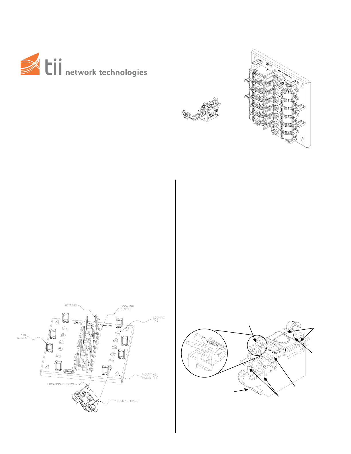
Model tii 99S SERIES
MDU ADSL2+/VDSL2 Splitter Modules
Model tii 712 SERIES
12 Pair Mounting Plate
Installation Note
Description
1. The tii 99S Series MDU ADSL2+/VDSL2
Splitter Module maintains a constant direct
connection between customer and central
office service provider. The Splitter Module is
equipped with the following IDC connections:
(2) POTS Lines, (1) CO Service IN, (1) Data
signal (Modem). Test ports are provided to
assure a signal is received from the central
office.
2. The tii 712 Series 12 Pair Mounting Plate is
configured to hold up to 12 ADSL2+/VDSL2
Modules.
Features
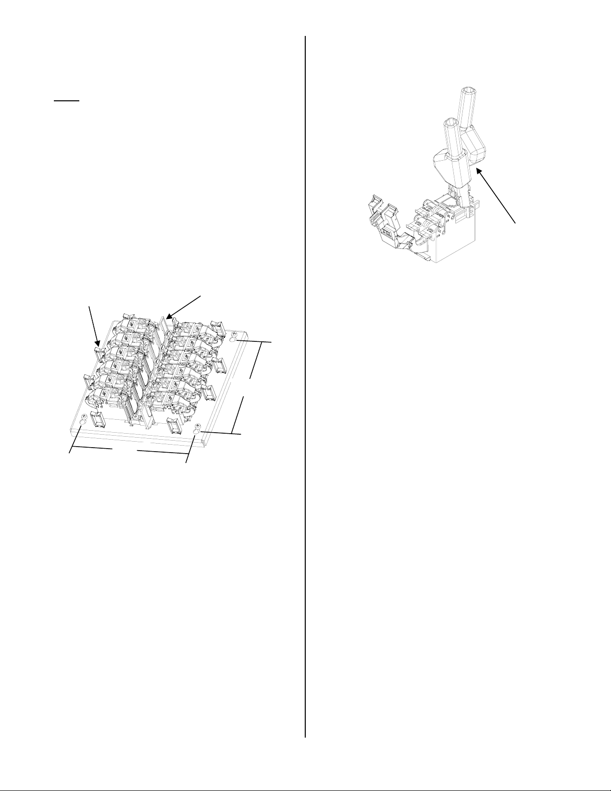
Installation
1. Hold the Splitter Module with the cover pivot
side on the right.
2. Angle the module so that the locking hinge is
secured under the locking tab (See Figure 1).
3. Align the (2) front locating fingers with the
locating slots. Engage the right end ledge
under the retainer. (See Figure 1).
4. Push the left side end down until the latch
snaps closed.
5. Follow steps 1-4 for the remaining module
installations.
6. Mount the 712 mounting plate with #10 sheet
metal screws of the appropriate length. The
mounting center dimensions are 6 3/4 x 6 7/8
(See Figure 3).
CO-IN
Test Ports
Locking
Hasp
Figure 1
Locking Hinge
Figure 2
Data-IN
Customer Wiring
Page 2
Wiring
√
1. Do not strip wire insulation from wires to be
terminated to Splitter Module.
Note:
√
IDC’s accept 22-26 AWG solid wire.
Wires should be aligned to the corresponding
holes. Green wire to the “T” (GRN) labeled wire
guide and the Red wire to the “R” (RED)
labeled wire guide.
2. Insert wires into wire guides at the same time
until they bottom out. While holding wires in
wire guides, terminate rocker with thumb.
Lower rocker all the way (See Figure 2).
3. Terminate Central Office service lines to CO-
IN (See Figure 2).
4. Prior to connecting POTS and Data Lines
confirm Central Office (CO-IN) connection at
the test ports using test clips and appropriate
test equipment (See Figure 3).
Module Dividers
Wire Guides
6 7/8”
Figure 3
5. Two telephone voice (POTS) pairs and one
DSL line (DATA) can be connected to a single
Splitter Module (See Figure 2).
6. Dress wires through wire guides and use
cable ties as needed (See Figure 3).
7. The customer has the option of installing a
#10 Master lock around the customer lock
hasp (See Figure 1).
6 3/4”
8. Insert test clips into test ports and follow
company procedure for testing (See Figure 4).
Figure 4
Test Clips
(Not Included)
 Loading...