

Page 1
1385 Akron Street TII 605 Series
Copiague, NY 11726 Aerial Terminal Enclosure
Customer Service/Sales 888-844-4720 Pat. Pending
Rev D 11/06
INSTALLATION NOTE
Model 605-5
Model 605-50
1. General
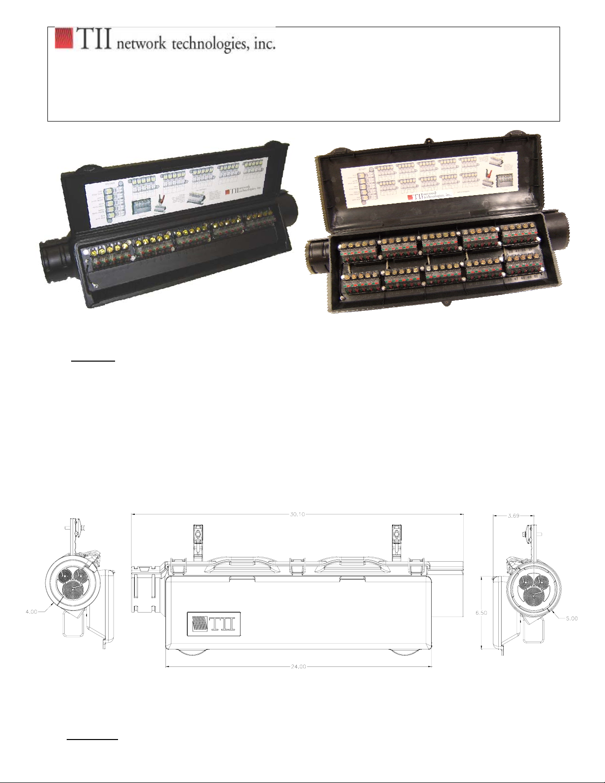
1.1 The Series 605 Aerial Terminal Enclosure with external bonding hanger brackets are
designed for fixed count terminating, non-protected up to 50 pair. The 5” x 30” (127mm x
762mm) terminal is available empty to handle configurations of 5 thru 50 pair. It can
accommodate a 3” (76mm) diameter splice bundle and cable up to 1.75”(44mm) diameter.
1.2 The ADX-5T terminal block is filled with a gel sealing compound to provide environmental
protection.
1.3 Dimensions:
2. Warranty
TII P/N: 92221501
Page 2
2.1 See TII Warranty. If this unit fails during the warranty period, the factory should be
requested to authorize return. Return the unit prepaid. Units that fail due to normal wear or
abuse should be discarded.
3.0 Carton Contents
3.1 Product Contents are as follows: 3.2 Additional Materials Required
(1) Sealed Aerial Terminal Body • Cable Ties
(1-10) Sealed Termination Blocks (ADX-5T) • Cable Spacers
(2) Aerial Hangar Straps • Vinyl Tape
(3) Stainless Steel Latches • Moisture Resistant Splicing
Connectors
(2) Entry Cable Grommets
(2) Ground Braid Assembly
(1) Cable Ground Bar
(1-5) Service Cable’s
(2) Vent’s
Aerial Hangar Strap (X2)
Cable Entry Grommets
(X2)
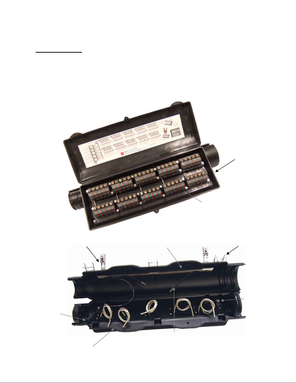
Model 605-50
Aerial Cable Ground Bars
Terminal Housing
ADX-5T Sealed Termination
Blocks (5-Pair Blocks)
Stainless Steel Latches (X3)
Vent
Terminal Block Cable Stubs
Ground Braid Assembly
TII P/N: 92221501
Page 3

4.0 Cable Preparation
4.1 Prepare cable and strand as shown in Figures 1 & 2.
Figure 1
Note: Suggested method in preparing the outer sheath on both single and double sheath
cables.
Single Sheath Cable
Cable Sheath
Core Wrap
Slit for Ground Stud Installation
Cable Sheath
1" (25mm)
Slit Slit
1/2" (13mm)
Figure 2
Double Sheath Cable
1/2" (13mm)
Cable Sheath
Inner Sheath
Slit On Cables Less Than 3/4" In Diameter
Cable Sheath
1 1/2" (38mm)
Core Wrap
1/8" (3mm)
TII P/N: 92221501
Page 4
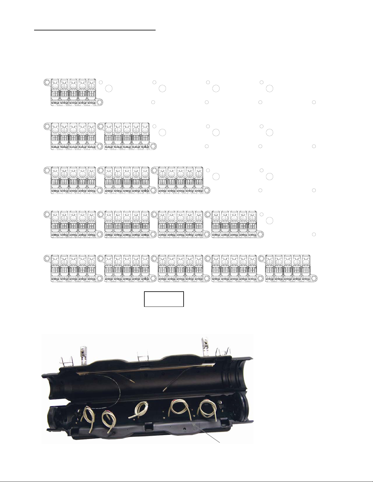
5.0 ADX-5T Terminal Block Installation
5.1 Select the proper mounting configuration in the terminal housing for the desired terminal block
locations (See Figure 3).
Note: Feed hole for the Terminal Block Tails is larger and sits to the far left.
5 PAIR BLOCK
10 PAIR BLOCK USING TWO 5 PAIR BLOCKS
15 PAIR BLOCK USING THREE 5 PAIR BLOCKS
20 PAIR BLOCK USING FOUR 5 PAIR BLOCKS
25 PAIR BLOCK USING FIVE 5 PAIR BLOCKS
Figure 3
Note: Any combination can be configured up to 50 pair.
5.2 Feed terminal block stub through appropriate hole(s) in box leading to the splice chamber.
Model 605-5
Terminal Block Stubs In Splice Chamber
TII P/N: 92221501
Page 5
5.3 Mount the terminal block(s) in multiple of five as required.
ADX-5T
TERMINAL BLOCK
#1
ADX-5T
TERMINAL BLOCK
#6
ADX-5T
TERMINAL BLOCK
#5
5-25 Pair Positions
30-50 Pair Positions
ADX-5T
TERMINAL BLOCK
#10
5.4 The Model 605-50 is equipped for mounting up to (10) ADX-5T sealed terminal blocks.
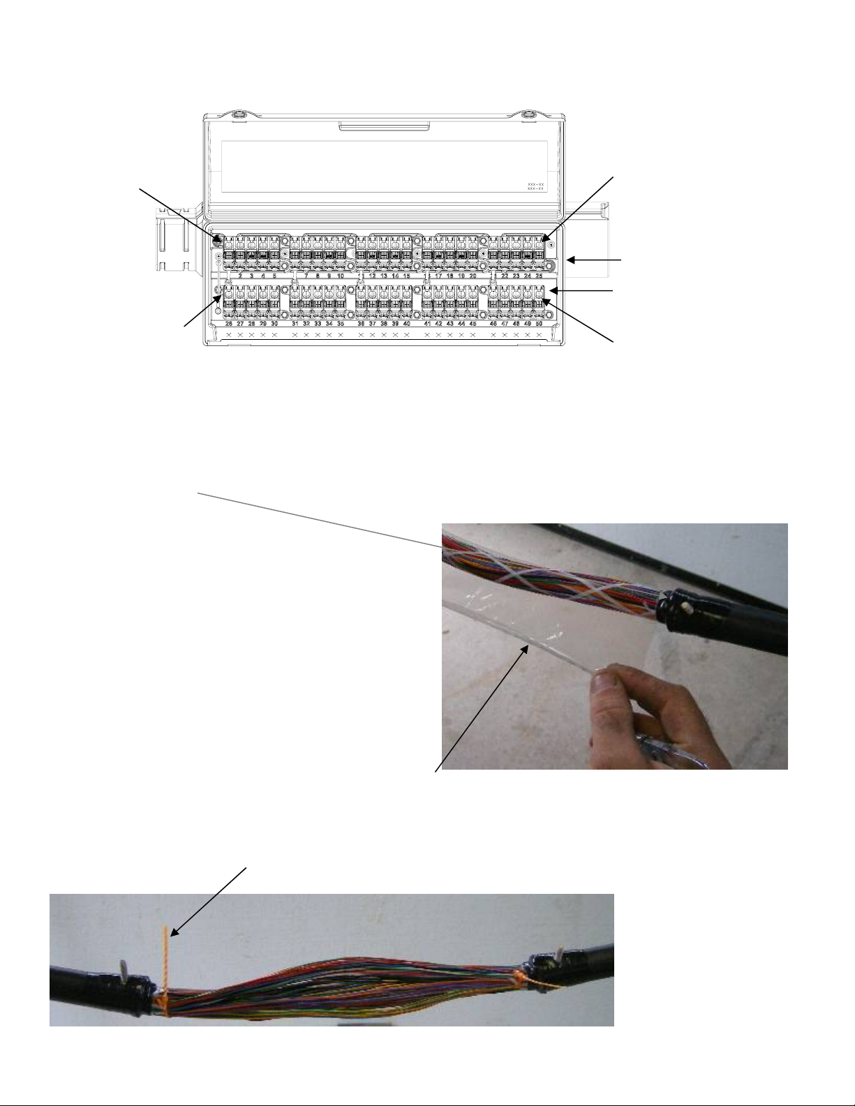
6.0 Terminal Installation, Bonding and Splicing
6.1 Bond the cable shield with approved shield bond connectors
Per approved practice.
6.2 Apply 4 – 5 wraps of vinyl tape around bond clamps then
Remove the pair protector
6.3 Select binder group to be spliced, and mark using standard practice.
TII P/N: 92221501
Page 6

6.4 Mount terminal to strand. Terminate shield bond connectors to terminal closure ground bond
straps; ensure bond clamps are pointing forward.
6.5 Using rip cord remove necessary amount of jacket from tail of ADX-5T blocks.
TII P/N: 92221501
Page 7

6.6 Splice as per standard practice.
6.7 Cable should be tie wrapped to the ground bar at each end for strain relief.
6.8 Install cable spacers as per standard practice.
TII P/N: 92221501
Page 8

7.0 Cable Entry Grommet Installation
7.1 Cut the cable entry grommet from the outside edge
to the appropriate ring diameter that matches the
Aerial Cable Diameter.
1
1¼” Maximum Diameter
1¾” Maximum Diameter
¼” Maximum Diameter
7.2 The Grommet is labeled 1 thru 7, the diameters
are listed per the drawing to the right. For best results cut out circumference
template at the bottom of the sheet. Wrap the template around
the cable using the start point as your reference point.
Ø
Ø1
Ø1
Ø1
(1)
3
Ø
8
(2)
5
Ø
8
(3)
3
4
(4)
(5)
1
8
(6)
3
8
(7)
5
Ø1
8
3
Ø1
4
Max Diameter
*The template has been perforated for easy removal, please tear down perforated lines.
Circumference Template
Start Point
1 2 3 4 5 6 7
4
3
2
1
7
6
5
4
3
2
1
1
Max Diameter
Ø1
4
Ø1
4
3
2
1
3
Ø
4
5
Ø
8
3
Ø
8
TII P/N: 92221501
Page 9

7.3 Cut end caps to fit cable, install in each end of terminal, and ensure a snug fit around cable.
A wrap of vinyl tape should be placed around each unit.
7.4 Install Cable Entry Grommets on the end of each cable
and position in body enclosure.
TII P/N: 92221501
Page 10

8.0 Adding or Changing Terminal Blocks
8.1 Using standard 7/16” terminal wrench remove existing ADX-5T block by backing out 2 nuts
on each side of block.
8.2 Remove block by pulling straight out.
8.3 Open new ADX-5T block and inspect. Insert tail of ADX-5T block into hole in terminal, left of
mounting space.
TII P/N: 92221501
Page 11

8.4 Align block with mounting holes in terminal housing
8.5 Tighten mounting nuts one half turn past tight, do not over tighten.
TII P/N: 92221501
Page 12

9.0 Replacement of Gel-filled ADX driver.
9.1 Using standard 7/16” terminal wrench, back driver nut off all the way out.
9.2 Using either your thumb and forefinger or a flat screwdriver, lift the back lock of the driver
off of the glide plate.
9.3 Remove the defective driver.
TII P/N: 92221501
Page 13

9.4 Remove a new driver from its packaging and inspect it. Place the new driver over the glide
plate, align with driver hole and snap into place.
9.5 Using standard 7/16’ terminal wrench, fully tighten the driver into the down position, ensure
driver is all the way down as it will affect the functionality of the tool-less connector if it is
not.
TII P/N: 92221501
Page 14

10.0 Drop Wire Termination
10.1 Open terminal box door.
10.2 Prepare Wire / Cable Per Standard Practice.
10.3 Using needle-nose pliers, push up through bottom
of terminal to accommodate wire installation.
10.4 Route wire through wire guides outside terminal.
10.5 Insert prepared wire/cable through access holes in the aerial enclosure. Use locking clip or tape
to eliminate pull out of drop
.
TII P/N: 92221501
Page 15

10.6 Tool-less rocker accepts 22-24awg wire, lower ports
To terminate 18.5-24 AWG wire (driver bolt actuated).
Upper Ports
Tool-less IDC Rockers
Lower Ports
Driver Bolt Mechanism
10.7 Upper Ports of tool-less IDC rockers accept 22-24
AWG wire. Lift rocker to full upright position. Insert wires.
Lower rocker to full down position.
Note: There is no need to open the driver to terminate 22-24
AWG wire.
10.8 Lower Ports terminate 18.5-24 AWG wire. Raise
Driver bolt mechanism to full up position by turning driver
bolt counter-clockwise. Insert Tip/Ring pair into lower
ports. Lower Driver to Fully seated position.
10.9 Complete termination log.
10.10 Close door and check for proper sealing.
TII P/N: 92221501
Page 16

11.0 Testing
11.1 Insert test clips into test ports and follow company
procedure for testing.
12.0 Accessories
• TII ADX-5T 5-Pair Gel Filled Terminal Block 20
• 00193501 Special Service Red Marker Tag
• 00193601 Replacement Gel Filled Drivers
5 sleeves (5pcs / sleeve)
• 00194101 Replacement Rubber End Seals
(Pair) 20 pairs.
Sealed Test Point Access
Tip/Ring (Butt Set Accessible)
Blocks
For ADX-5T,
20 bags (100pcs / bag).
TII P/N: 92221501
 Loading...