

Page 1
tii 5100
141 Rodeo Drive NETWORK INTERFACE DEVICE
Edgewood, NY 11717 TII P/N: 64013101
Customer Service/Sales 888-844-4720 Rev P 10/09
INSTALLATION NOTE
1.00 GENERAL
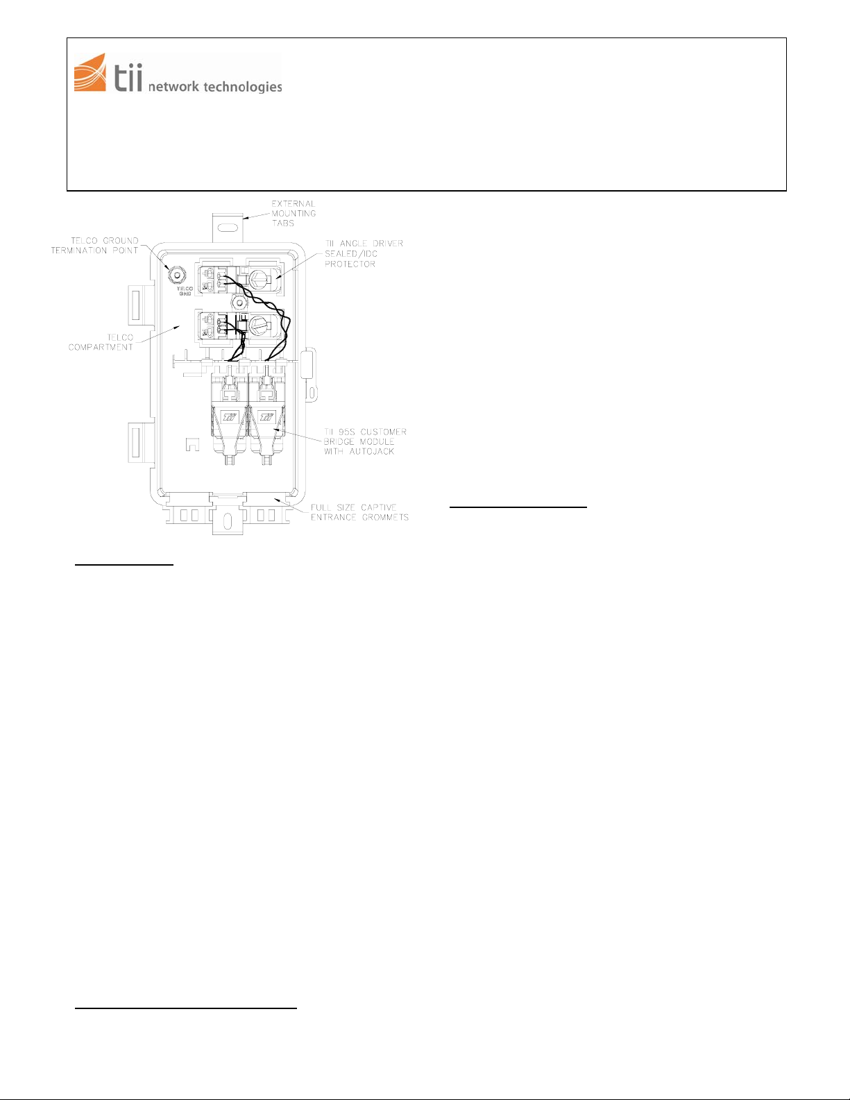
1.01 The TII 5100 Series Network Interface Device
(NID) provides an environmentally sealed
demarcation point between the telephone
service provider network and the subscriber’s
telephone wires. The NID may contain gel
sealed station protectors (TII Angle Drivers), or
other primary station protectors like TII 356, TII
127, etc., and sealed subscriber bridges (TII 95
Series). These primary surge protection
modules provide primary electrical protection
for subscribers. The TII 95 Series provides
subscriber connections and a demarcation test
access point.
1.02 Each Angle Driver module can connect one
pair of 18-24 AWG (1.02-0.51mm) central office
(c.o.) wire and two pair of 22-26 AWG (0.65-
0.4mm) subscriber bridge wires. Each can
make up to four subscriber extension lines
connections which will automatically disconnect
when the customer uses the RJ-11 port for
testing. Connections are created with insulation
displacement connection (IDC) blades and are
environmentally sealed.
1.03 The NID’s housing is constructed from rugged,
heat and solvent resistant, UV stabilized
materials.
2.00 CAUTIONS AND WARNINGS
• Use company-approved safety practices and
equipment.
Figure 1
• Only solid conductors can be used for
connecting to the Angel Driver and the TII 95S
Series Subscriber Bridges; Do Not Use
Stranded Wire.
• Stranded or solid wires can be used on binding
post termination primary protectors.
• Do not strip insulation from conductors when
terminating to an IDC connector.
• If the hook up wire, OSP wire, or central office
cable is physically larger than 22 AWG, a fusing
conductor of 22 AWG or smaller solid copper
wire with thermoplastic insulation must be used.
Install the fuse link per local practices and
approval agencies.
• This installation note may be used for binding
post terminating primary protectors
3.00 INSTALLATION
3.01 Open the front cover for easier access to the
mounting tabs (Figure 1).
3.02 To mount to wooden pole or wall, install two
screws through the slots in the housing
mounting tabs. Secure them to the required
service.
PrepareandRouteCables,Grounding
3.03 Route the central office (c.o.) wire into the
housing through the left grommet.
3.04 Remove the outer sheath from cable, exposing
conductors.
3.05 Secure the c.o. wire in place by installing a tie
wrap through the slotted clamp below the
grommet. Tighten the tie wrap to secure the
cable to the slotted clamp.
3.06 If the cable is shielded, remove 1” of sheath
and attach the ground lug to the shield.
3.07 Route the subscriber wire into the housing
through the right grommet.
3.08 Strip the outer jacket insulation from the
subscriber wire, exposing the insulated
conductors.
3.09 Secure the subscriber wire in place by installing
a tie wrap through the slotted clamp below the
grommet. Tighten the tie wrap to secure the
wire to the slotted clamp.
 Loading...