

Tii 506F User Manual
P/N 92235001 • Rev A• ECN 10-092 • 5/19/2010
Warranty: If this unit fails during the warranty period, contact tii customer service to authorize return. Unit may be returned prepaid.
Model 506F
Fiber Interface Device
Installation Note
Description
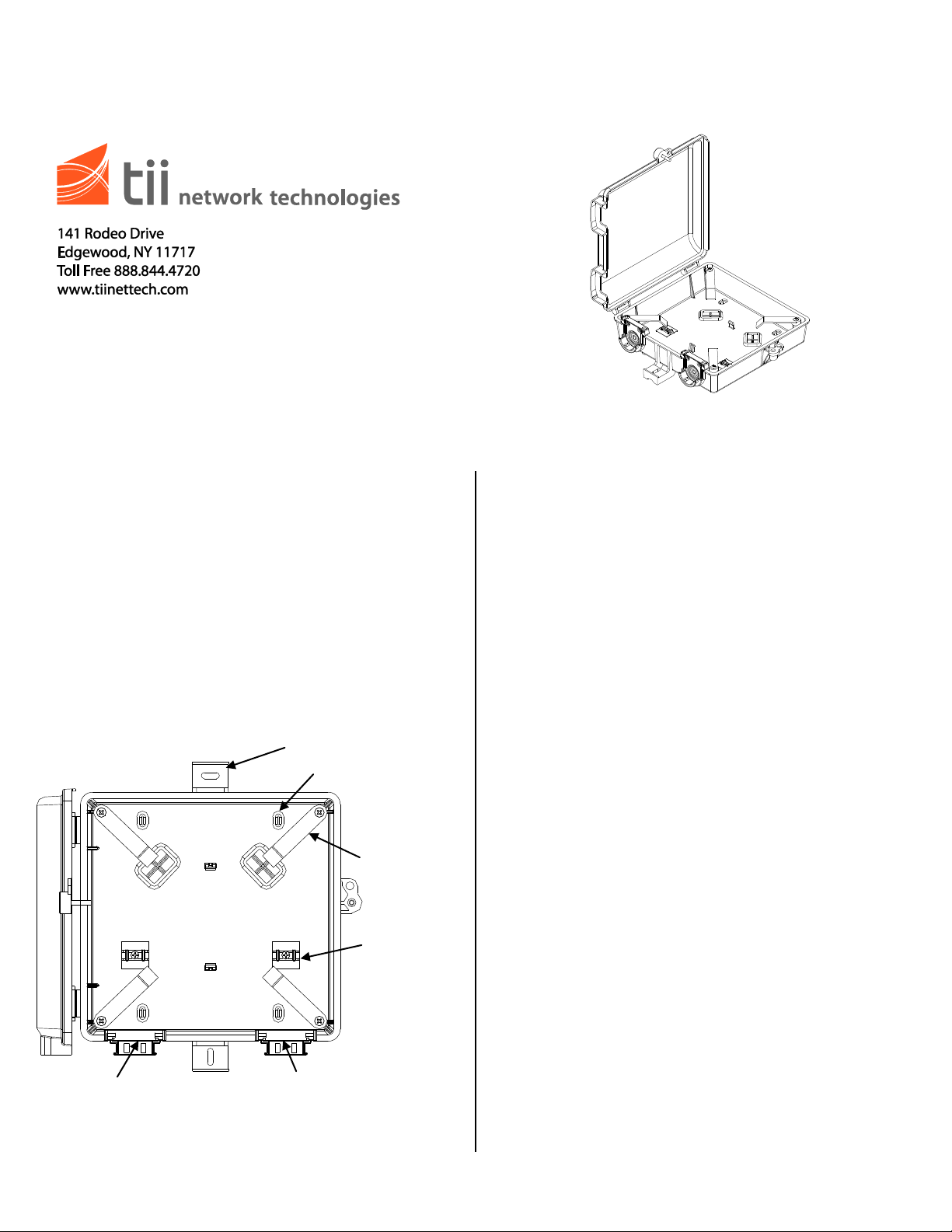
Strain Relief
Pads
Entry
Grommet
Exit
Grommet
Slack Retention
Fingers
Internal Mounting Holes
External Mounting Ears
Installation
1. The TII 506F Fiber Optic Interface Device is a
compact fiber optic connectivity and fiber slack
storage enclosure.
2. The large split grommets located at the bottom
of the base allow Telco drop lines and fiber
cables to enter and exit the device.
3. The TII 506F allows for sufficient drop/fiber
cable slack storage.
Features
Figure 1
1. Mount the 506F Device so as to minimize the
possibility of dirt or moisture getting into the
enclosure.
2. 506F Devices mounted side-by-side or end-toend should be placed so covers can easily be
opened.
3. Mount the 506F Device vertically on a flat
surface using appropriate hardware (the
length of the mounting screws should allow for
1/8” of length within the enclosure).
4. The internal mounting holes are covered with
a thin film of plastic, which are easily punched
out, to maintain the environmental integrity of
the enclosure (See Figure 1).
5. In addition to the internal mounting holes
mentioned in step 4, there are external
mounting ears which are provided for exterior
mounting. Mount as previously stated using
the appropriate mounting hardware and
methods (See Figure 1).
6. You are now ready to place the drop/fiber
cable slack into the enclosure and prepare for
wiring.
Wiring
1. Punch a hole through the left grommet and
guide the cable through the entry grommet.
2. If required, splice any drop cables and
customer fiber cables with the required
connectors.
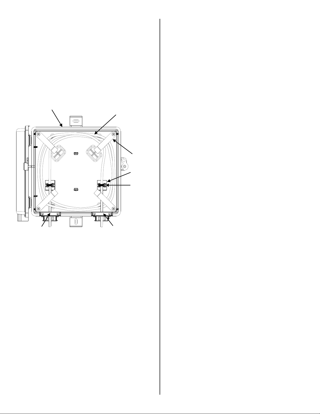
3. Wrap the excess drop cable/fiber cable slack
Tie-Wrap
Strain
Relief Pad
Base
Slack
Retention
Fingers
Cable Slack
Entry
Grommet
Exit
Grommet
in the clockwise direction and place it into the
base enclosure and under the slack retention
fingers.
4. Use a tie-wrap to hold any spliced connections
and cables to the strain relief pads.
5. Punch a hole through the right grommet and
guide the cable through the exit grommet.
6. Close and secure the cover. Tighten the
security hex screw until it is snug. Be sure not
to over tighten the screw.
Figure 3
 Loading...