

Page 1
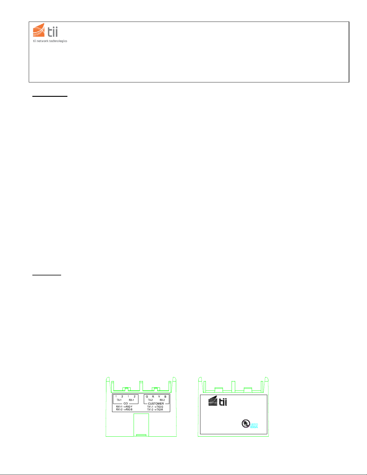
Figure 1 – TII Model 372-S / 372-S2 100 Base-T Protector
(Model 372-S Shown Below)
U.S. PAT. NO. 5,790,363
Protector
Signal Circuit
100 BASE-T PROTECTOR
372-S2
TII 372-S/372-S2
141 Rodeo Drive 100 BASE-T SURGE PROTECTION MODULE
Edgewood, NY 11717 P/N 922098
Customer Service/Sales 888-844-4720 02/08 Rev F
INSTALLATION NOTE
Introduction
This installation note provides the description and installation
steps for the TII 372-S/372-S2 Sealed IDC Termination 100
Base-T Surge Protection Module. This module is designed to
be used for 100 Base-T IEEE 802.3 network protection. (See
Figure 1)
The TII 372-S/372-S2 100 Base-T Surge Protection Module
is intended for indoor/outdoor use within listed compatible
NIDs, which have been evaluated for the applicable
environment.
Each module is capable of terminating 22-24 AWG solid
copper wires.
NATIONAL ELECTRIC CODE REQUIREMENTS:
THE PROTECTOR SHALL BE INSTALLED PER NATIONAL
ELECTRIC CODE ANSI/NFPA 70, ARTICLE 800, SECTION
C, AND SHALL MEET ALL OTHER APPLICABLE LOCAL
SAFETY CODES. BOTH THE SERVICE WIRE TRANSMIT
AND RECEIVE PAIRS MUST BE CONNECTED FOR THE
PROPER FUNCTION OF THE UNIT. BOTH THE RECEIVE
AND TRANSMIT CIRCUIT WIRES FROM THE CO MUST BE
TERMINATED AT THE RESPECTIVE CO SIDE TERMINAL
BLOCK.
CAUTION: RISK OF SHOCK IF NOT INSTALLED IN A
LISTED OUTDOOR/INDOOR ENCLOSURE
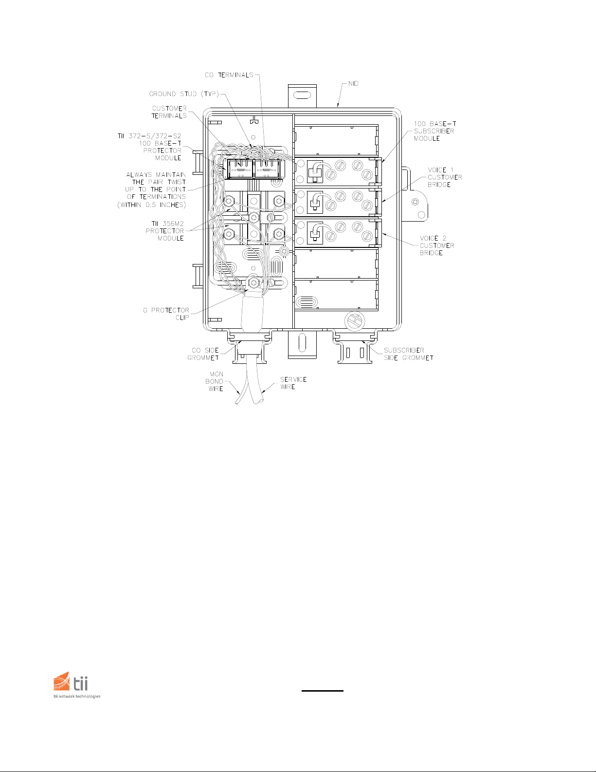
Installation (See Figure 2)
1. Remove the unit from the packaging and inspect it
carefully for damage. If found damaged, obtain another.
2. Install the TII 372-S/372-S2 module in the NID under the
lower nut of the ground stud and tighten securely. For
illustration purposes Figure 2 shows the 372-S/372-S2
protector mounted in slot 2.
3. Pass the appropriate earth ground wire through the CO
(central office) side grommet of the NID and connect it to the
ground stud.
4. Run and connect the earth ground wire to the approved
ground source making the run as short and straight as
possible.
5. Pass the service wire through the CO side grommet of the
NID.
6. After stripping the jacket and appropriately terminating the
shield of the service wire to the G protector clip, secure the
G protector clip under the washer and nut of the NID ground
terminal as shown in Figure 2.
7. Disengage “CO” side rocker using a ¼” flat screw driver in
the slot provided on top of the rockers.
8. Untwist about 1” of CO (service) side, transmit and
receive cable pairs. Insert the unstripped wires through the
rocker wire guide holes until all wires hit the back end of the
rocker.
9. Hold the wires in place and lower the rocker to its
terminated position-using thumb. (A flat ¼” screw driver could
be used to assist in terminating wires.)
10. Disengage “customer” side rocker.
11. Untwist about 1” of red/green and yellow/black wire pairs
from the 100 Base-T subscriber module. Guide wires
through the wire guide holes on the customer side rocker.
Make sure all the wires are fully seated.
12. Follow Step 9 above to terminate “customer” side wires.
13. Route wiring in NID as to avoid sharp bends. Close
cover and secure in place. Perform all customary tests.
Page 2
Warranty
See TII Warranty. If this unit fails during the warranty
period, the factory should be requested to authorize
return. Return the unit prepaid when authorization is
received. Units that fail due to abuse or normal wear
should be discarded.
Figure 2 – Typical Installation
141 Rodeo Drive
Edgewood, NY 11717
Customer Service/Sales 888-844-4720
 Loading...