

Page 1
TII 347-07-2-1
Figure 2
Customer Side Cable
Telco Side Cable
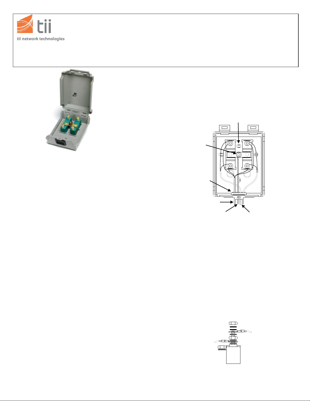
Figure 1
Customer Side Cable
Line 1 and Line 2
Telco
Side Cable
Ground Stud /
Binding Post
Grounding
Conductor
Grommet
Knockout (Typical)
TII 347 Series
141 Rodeo Drive Station Protectors
Edgewood, NY 11716 TII P/N: 92223701
Customer Service/Sales 888-844-4720 INSTALLATION NOTE 11/07 Rev B
1. GENERAL
1.1 The TII 347 Series Station Protectors consist of one or two
Protector Modules in a top hinged enclosure with integral
ground stud (See Figure 1).
1.2 The TII 347 is available with a variety of protector modules
with standard binding post termination or sealed IDC
termination.
1.3 The plastic base is molded with knock out holes for
mounting. A captive nylon insulated nut may be provided to give
a degree of tamper proofing, and for easy installation and
removal as an option (See Figure 1).
1.4 A flexible grommet is located in the center of the base to
provide a seal for Telco cable, customer cable and grounding
conductor wiring. (See Figure 1.)
National Electric Code Requirement
The protector shall be installed per National Electric Code
ANSI/NFPA 70, Article 800, Section C, and shall meet all
applicable local safety codes.
2. WARRANTY
2.1 See TII Warranty. If this unit fails during the warranty
period, the factory should be requested to authorize
return. Return the unit prepaid. Units that fail due to
normal wear or abuse should be discarded.
3. INSTALLATION
3.1 Precautions
3.1.1 Mount the station protector so as to minimize the
possibility of dirt or moisture getting into the protector.
3.1.2 Station protectors mounted side-by-side or end-to-end
should be placed so covers can be easily removed.
3.1.3 Where protection for multiple services is required, it is
recommended that a protected building terminal in an interior
terminal box be installed in place of station protectors.
3.2 Mounting
3.2.1 Mount the station protector vertically on a flat surface
using appropriate hardware (the length of the mounting screws
should allow for 1/8” of length within the protector.
4. WIRING
4.1 Ground
4.1.1 Insert the grounding conductor, the customer side
cable and the Telco side cable through the grommet in the
base of the protector (See Figure 1).
4.1.2 Terminate one end of the grounding conductor (No. 6
AWG) on the ground stud / binding post and the other end to
an appropriate ground source. (See Figure 1.)
4.2 STATION PROTECTOR WIRING
(If equipped with binding post protection)
4.2.1 For binding post termination type protectors; terminate
the Customer Side cable in between the bottom set of washer
and bottom nut of the appropriate stud (one conductor to Tip
and one to Ring) and tighten down. (See Figure 2.)
4.2.2 Terminate the Telco Side Cable under the top set of
washers and the top nut of the appropriate stud (one
conductor to Tip and one to Ring) and tighten down. (See
Figure 2).
P/N: 92223701
Page 2
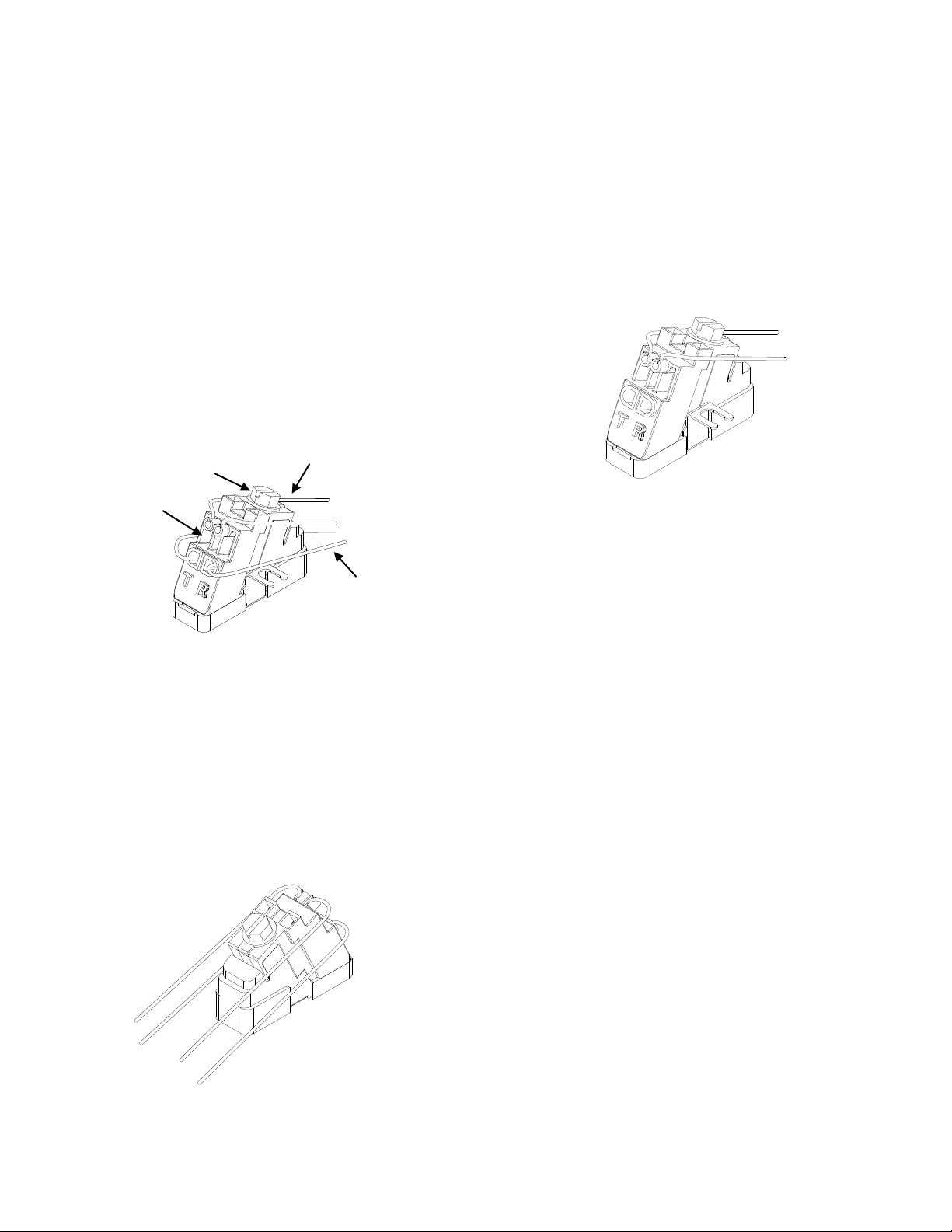
Figure 3
Strain
Relief
Drive
Screw
Telco Side Cable
Customer Side Cable
Figure 4
Figure 4
Figure 5
4.3 STATION PROTECTOR WIRING
(If equipped with angle driver module)
4.3.1 For sealed IDC termination type protectors; terminate
the Telco Side Cable by loosening the drive screw and pulling
up the driver and insert un-stripped Telco Side Cable in the
bottom ports (one conductor to Tip ‘T’ and one to Ring ‘R’)
until they are seated at the bottom of the ports. (See Figure 3.)
4.3.2 Insert un-stripped Customer Side Cable in the top ports
(one conductor to Tip ‘T’ and one to Ring ‘R’) until they are
seated at the bottom of the ports. (See Figure 3.)
4.3.3 Re-tighten the drive screw bring the driver down to
the protector base. (See Figure 3.)
4.3.4 Set the Customer Side Cables into the strain relief
cutouts on the sides of the Customer Side Cable
ports. (See Figure 3.)
4.3.5 Loop back unused station wire conductors and coil
around the station wire jacket or store in such a
manner as to prevent them from coming in contact
with protector terminals or bare wires.
5. Angle Driver Testing
Upper and Lower Port Connected
5.1.1 Feeder and subscriber wires must be segregated between
the upper and lower ports to facilitate isolation testing (see
Figure 4).
5.1.2 With Driver in the fully closed position, insert test clips into
tip/ring test port access holes located at top of driver. Perform
customary tests.
Testing Subscriber Connections
5.2.1 Loosen drive screw so driver is in the full upright
position.
5.2.2 Remove Telco wires from lower ports of driver.
5.2.3 Tighten drive screw so driver is in the full down position.
5.2.4 With Driver in the fully closed position, insert test clips
into tip/ring test port access holes located at top of driver.
Perform customary tests.
P/N: 92223701
 Loading...