

Page 1
TII 320-71-NIZS
TII 325-1LM-NIZS
TII 320 NIZ / TII 126NIZ
TII 325 NIZ / TII 326NIZ
141 Rodeo Drive Station Protector With Network Interface
Edgewood NY 11717 Rev C 01/08
Customer Service/Sales 888-844-4720
INSTALLATION NOTE
GENERAL
a) This installation note covers the description and
installation of the TII 325 NIZ, 326 NIZ, 126 NIZ and
the 320 NIZ hereafter referred to as the unit. This
product is designed to combine a single pair TII 325,
326, 126, or 320 Station Protector with a single pair
Network Interface Device.
b) The unit is furnished complete with a mounting base,
an RJ-11 interface jack and plug, customer wiring
bridge , retaining nut, cover, and normally a protector
module / angle driver. The unit may also be furnished
with an optional ringer termination circuit.
1. WARRANTY
a) See TII Warranty. If this unit fails during the warranty
period, the factory should be requested to authorize
return. Return the unit prepaid. Units that fail due to
normal wear or abuse should be discarded.
2. DESCRIPTION
a) The unit is an adaptation of the TII 325, 326, and 320
series single pair Station Protector. The standard
cover of those products is replaced by a cover
assembly that isolates the telco wiring and station
protector from the customer. The RJ-11 plug and jack
are supplied with weather resistant grommets.
b) The cover assembly is held in place with a sturdy nylon
nut. The unit has a hinged, side opening cover,
complete with a provision for a security seal. Testing
instructions are provided inside the cover.
c) The product is furnished complete and requires no
special tools for installation.
3. INSTALLATION WITHOUT STATION ELECTRONICS
a) Remove the unit from the carton and inspect it
carefully for damage. If the unit is damaged, obtain
another.
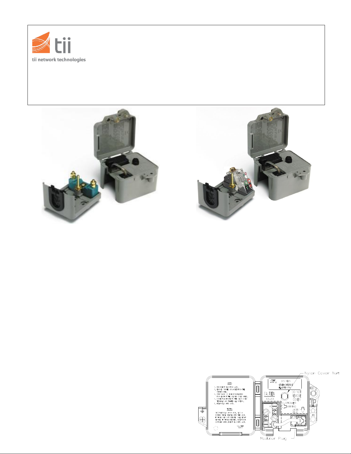
b) Open the hinged door on the face of the unit and
unplug the modular plug from the jack (See Figure
1).
c) Remove the cover assembly from the base by
loosening the nylon cover nut and then pulling the
cover assembly away from the base (See Figure
1).
d) To mount the protector base, select the desired
hole pattern and knock out the plastic web over the
holes with a screwdriver. Position the base to the
mounting surface and attach it will appropriate
hardware.
e) Connect a proper station protector ground to the
molded-in ground stud using locally approved
grounding methods.
TII P/N: 92202701
Page 2
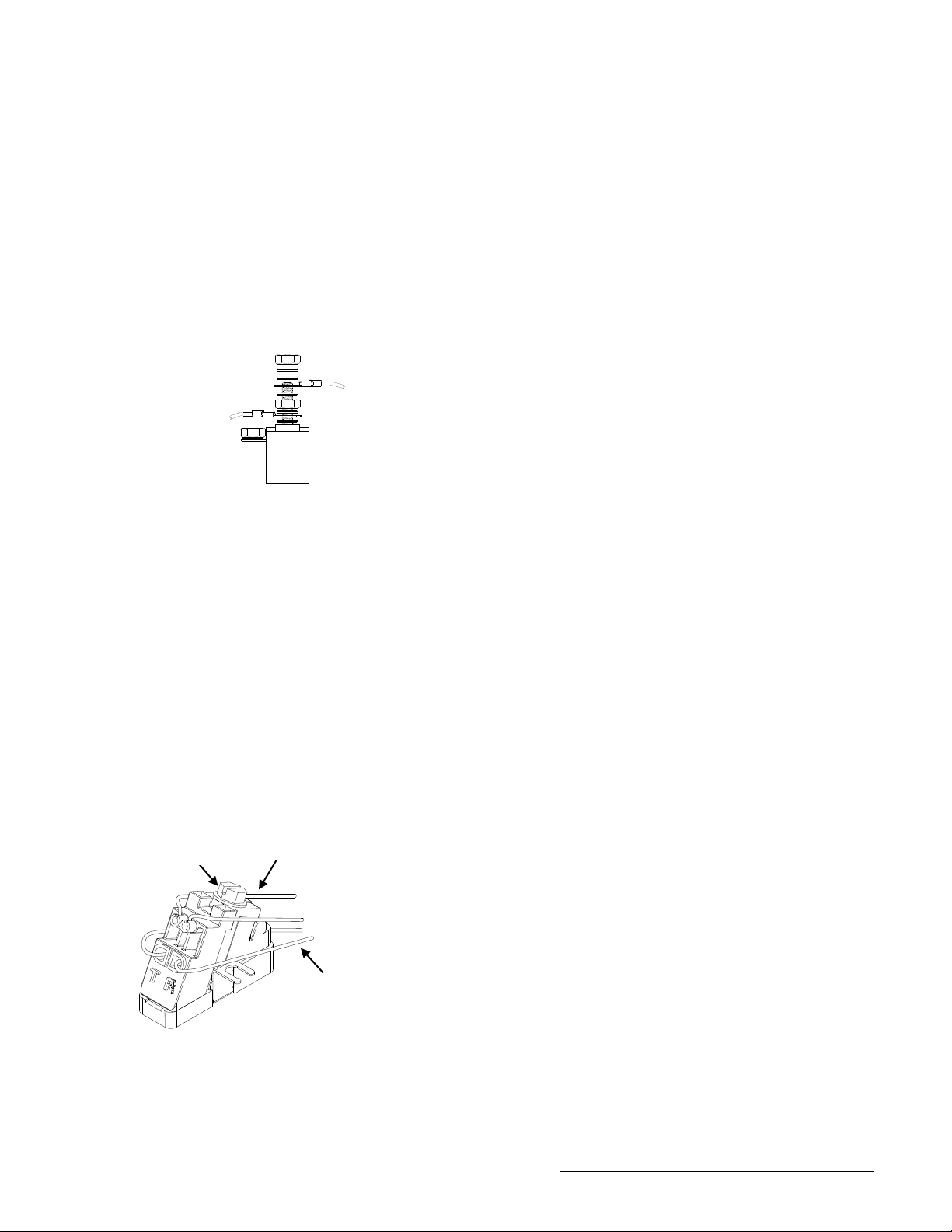
Figure 2
Customer Side Cable
Telco Side Cable
Telco Side Cable
Customer Side Cable
Figure 3
Figure 1
Angle Driver Screw
4.1 STATION PROTECTOR WIRING
(If equipped with binding post protection)
a) Connect the drop wire to the Tip and Ring of the
protector module, placing the wire under the bottom
nut on each stud for station protector module (See
Figure 2).
b) Turn the cover assembly over and locate the spade
tipped red and green conductors that are attached to
the modular jack. Connect them to the Ring and Tip
binding posts of the protector module respectively.
c) Inspect the ground wire and drop wire connections.
d) See 4.2 3 Final Installation Steps
4.2 STATION PROTECTOR WIRING
(If equipped with angle driver)
4.2.1 Upper Port Subscriber Connections
a) Turn the cover assembly over and Cut spade lugs from
Red and Green conductors that are attached to the
modular jack.
b) Do not strip wire insulation. Make certain wire ends
are cut flush with insulation.
c) Unscrew Angle Driver screw to full upright position.
d) Fully insert the two wires into their respective Tip and
Ring (color-coded) ports.
e) While holding the two Customer side wires in place
tighten Drive Screw to full down position.
4.2.2 Lower Port Telco Connections
a) Do not strip wire insulation. Make certain wire ends
are cut flush with insulation.
b) Unscrew Angle Driver screw to full upright position.
c) Fully insert the two wires into their respective Tip and
Ring (color-coded) ports.
d) While holding the two Telco wires in place tighten
Drive Screw to full down position.
e) See 4.2.3 Final Installation Steps.
4.2.3 Final Installation Steps
a) Locate the yellow and black conductors also
attached to the modular jack and insulate them with
a short piece of tape. Dress them to the side so as
not to interfere with the working of the unit. (The
yellow and black wires may also be terminated on
the protector ground post if desired.)
b) Carefully fit the cover assembly onto the base of
the protector, ensuring that no loose ends or other
wire pieces are protruding between the cover and
base.
c) Locate the ground stud with the nylon nut of the
cover and screw it down until the cover is fitted
snugly to the base.
d) Carefully place the station wire in the lip of the
grommet and terminate the conductors on the
customer wiring bridge. Inspect for shorts and
broken wires.
e) Insert the modular plug into the modular jack and
close the hinged door.
4. INSTALLATION WITH STATION ELECTRONICS
a) Follow steps 4a -4e then proceed to next step.
b) Terminate the Tip-in and Ring-in leads of the
electronics assembly onto the protector module
binding posts or angle driver termination, and
ground stud if required.
c) Take a short piece of station wire and connect the
red and green conductors respectively to the
Ring-out and Tip-out terminals of the station
electronics assembly.
d) Run this wire to the protector or angle driver and
dress the end into the protector. Remove a portion
of the jacket and prepare the red and green
conductors to be spliced to the spade tipped red
and green conductors of the cover assembly of the
unit.
e) Locate the red and green spade tipped conductors
attached to the modular jack and cut off the spade
tips.
f) Using a Scotch-Loc or B wire connector, or some
other splicing device, splice the red conductor from
the Ring-out of the electronics assembly to the red
conductor attached to the modular jack. Splice the
green conductor from the Tip-out of the electronics
assembly to the green conductor attached to the
modular jack.
g) Dress all loops and extra conductors neatly inside
the protector and carefully fit the cover assembly
onto the base of the protector. (The yellow and
black wires from the modular jack may be insulated
and taped back, or terminated on the protector
ground post.)
h) Complete installation by following steps 4.2.3 (c-e).
TII P/N: 92202701
Page 3

5. TESTING
a) When the installation of the unit has been completed,
standard test procedures should be performed from
the customer’s telephone to ensure that all
connections are correct and that no grounds or short
circuits are present.
TII P/N: 92202701
 Loading...