

Page 1
141Rodeo Drive
Edgewood, NY 11717 tii 320/321/325/326
Toll Free 888.844.4720 Totel® Failsafe TFS® Station Protectors
www.tiinettech.com Rev D 05/10
INSTALLATION NOTE
1. GENERAL
• The TII Totel Failsafe
mounting base, protector module, grommet, and fitted cover
with nylon fastening nut.
• The plastic base is molded with two shallow rectangular wells,
one above and one below the ground stud / binding post
(Figure 1) and mounting holes designed to fit existing
protector mounting holes when changing station protectors.
• The number of protectors that can be connected to various
size copper-insulated ground wires is listed in Table A below.
Ground Wire Capacity
Wire Size (AWG) No. of Primary Protectors
12 1 to 2
10 3 to 5
6 6 or more
• National Electric Code Requirement. The protector shall
be installed per National Electric Code ANSI/NFPA 70,
Article 800, Section C, and shall meet all applicable local
safety codes.
2. INSTALLATION
Precautions
• Mount the station protector so as to minimize the possibility
of dirt or moisture getting into the protector.
• Station protectors mounted side-by-side or end-to-end
should be placed so covers can be easily removed. The
cover is furnished with a nylon retention nut which secures
the cover to the base (Figure 1). The cover is secured or
removed by using a 3/8” terminal wrench.
• Where protection for multiple services is required, it is
recommended that a protected building terminal in an
interior terminal box be installed in place of station
protectors.
Mounting
TII 325 1M
®
TFS® Station Protectors consist of a
TABLE A
Protector Well
Protector Modules
Retention Nut
Ground Stud / Binding Pos
Base
Cover
Grommet
Figure 1
t
• Mount the station protector vertically on a flat surface using
appropriate hardware (the length of the mounting screws
should allow for 1/8” of length within the protector).
• The mounting holes are covered with a thin film of plastic,
easily punched out, to maintain the environmental integrity
of the protector (Figure 2).
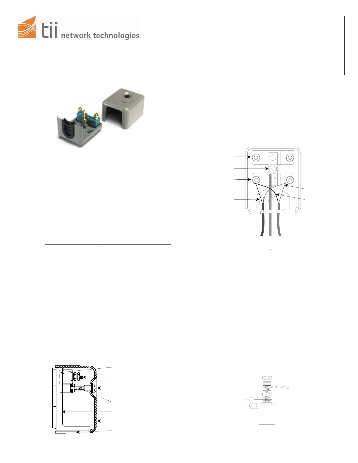
Two Pair Wiring Scheme
Station Protector Housing
(Cover Removed)
Protector
Ground Stud
Protector
Mounting Hole
Ring Conductor
Tip Conductor
Telco Side Cable
Customer Side Cable
Grounding Conductor
Figure 2
Wiring
• Insert the grounding conductor, the customer side cable and
the telco side cable through the grommet located in the
center of the base lip.
• Terminate one end of the grounding conductor (No. 6 AWG)
on the ground stud / binding post and the other end to an
appropriate ground source (Figure 3).
• Terminate the Telco Side cable in between the bottom set of
washer and bottom nut of the appropriate stud (one
conductor to Tip and one to Ring) and tighten down
(Figure 3).
• Terminate the Customer Side Cable under the top set of
washers and the top nut of the appropriate stud (one
conductor to Tip and one to Ring) and tighten down
(Figure 3).
• Loop back unused station wire conductors and coil around
the station wire jacket or store in such a manner as to
prevent them from coming in contact with protector
terminals or bare wires.
Telco Side Cable
Customer Side Cable
Figure 3
TII P/N 922137
 Loading...