

Page 1
P/N 92242801 • Rev A • ECN 14-215 • 9/29/2014
Warranty: If this unit fails during the warranty period, contact tii customer service to authorize return. Unit may be returned prepaid.
Model 312 Series
Station Protector
Installation Note
Description
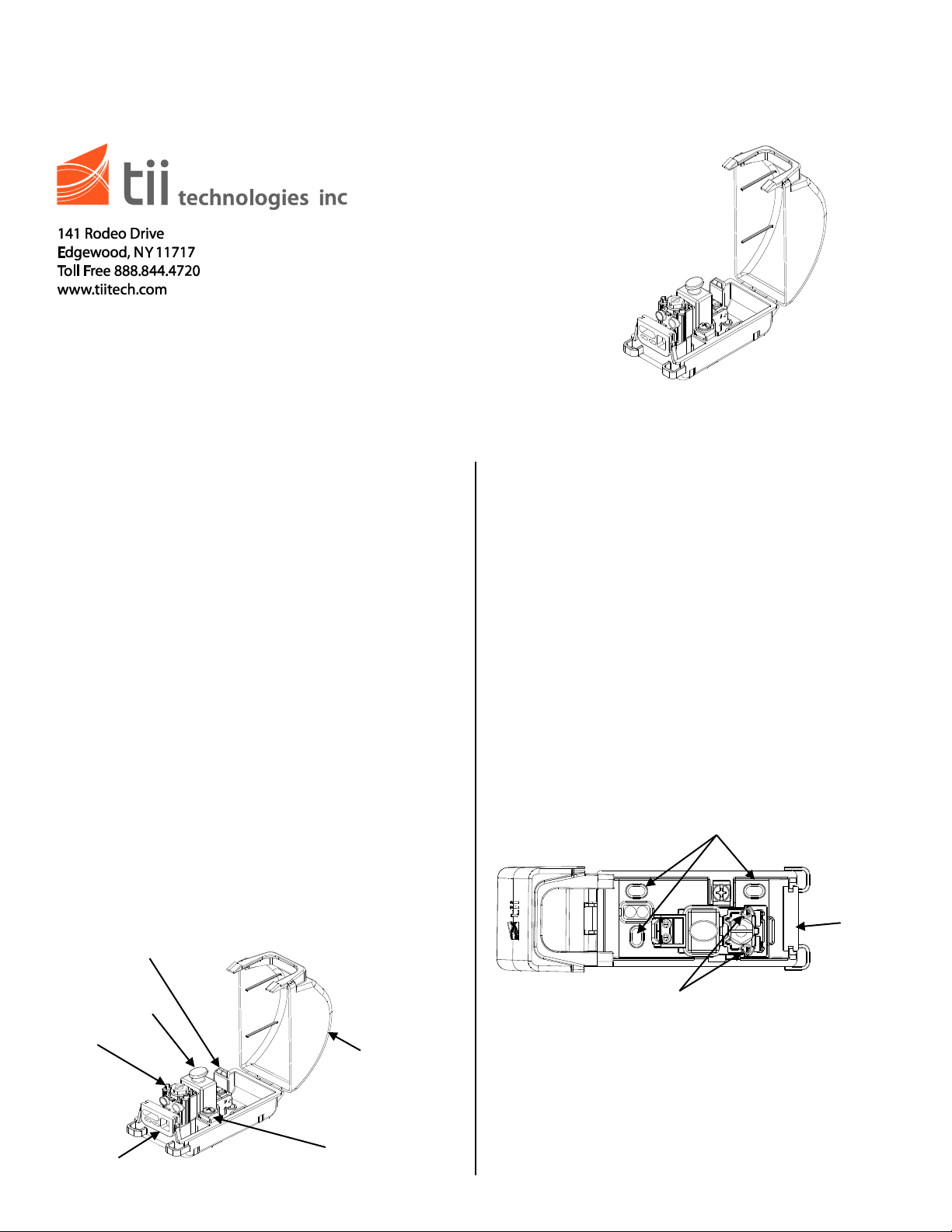
Mounting holes
Grommet
Test Ports to check dial tone
Protector
(Optional)
Ground Screw/
Retaining Post
Protector
Module
Grommet
312 Station
Protector
Tool-less IDC
Rocker
Installation
1. The TII 312 Series is a Station Protector which
consists of a DRM Series Surge Protector
Module in a 312 Protector Enclosure with a
molded in ground stud.
2. The 312 Protector Enclosure has a removable
grommet located in the center of the base lip
to allow Telco cable, customer cable and
grounding conductor penetration. It is
equipped with a universal grounding and
mounting tab. (See Figure 1).
3. The TII DRM Series Station Protector Module
utilizes gel-sealed screw drive IDC input
connections & tool-less output IDC rockers.
They are also equipped with integral sealed
test points for ease of troubleshooting.
4. All ports accept .4mm to 1.5mm awg wire.
5. The TII DRM Series Station Protector Modules
are equipped with removable 5 pin protector
modules and are available in non-protected
and protected versions.
Features
Figure 1
1. Mount the station protector so as to minimize
the possibility of dirt or moisture getting into
the protector.
2. Station protectors mounted side-by-side or
end-to-end should be placed so covers can be
easily removed.
3. Where protection for multiple services is
required, it is recommended that a protected
building terminal in an interior terminal box be
installed in place of station protectors.
4. Mount the station protector vertically on a flat
surface utilizing the mounting holes shown in
Figure 2 and using the appropriate hardware
(the length of the mounting screws should
allow for 1/8” of length within the protector).
Figure 2
Wire Entry
Page 2

Wiring
Drive Screw – open to
terminate wires
Insert ground
wire here
Ground Screw
Insert input
wires here
Insert output
wires here
Rocker – open to
to terminate wires
Testing
1. Insert input, output & ground wires through the
grommet as required.
2. Do not strip wire insulation. Make certain wire
ends are cut flush with insulation for all input
and output connections.
3. Unscrew Protector Module Driver Screw to the
full upright position (See Figure 3).
4. Fully insert the two input wires into their
respective tip and ring (color-coded) ports.
5. Insert while holding the two input connection
wires in place. Ensure wires are fully inserted
beyond the IDC connector. Tighten the Drive
Screw to the full down position (See Figure 3).
Pull on wires to ensure proper connection.
Wires should remain securely in place.
6. Lift rocker to the full up position (See Figure
3).
7. Hold the wires between thumb and index
finger (approx. 1/8” separation between wires).
8. Fully insert the output wires into wire their
respective tip and ring (color-coded) ports at
the same time until they bottom out.
9. While holding wires in the wire guides,
terminate rocker by lowering rocker all the
way.
10. Assure the rocker is in the down position (See
Figure 3). Pull on wires to ensure proper
connection. Wires should remain securely
in place.
1. Insert test probes into test ports (See Figure 2)
to check for dial tone.
11. Unscrew the ground screw and insert the
ground wire into the grounding retainer post.
Once inserted, tighten the ground screw to
hold the ground wire firmly in place (See
Figure 3). Be sure the other end is attached to
an appropriate ground source.
insert wires- close to
Figure 3
insert wires- close
 Loading...