

Page 1

P/N 92234601 • Rev A• ECN 10-048 • 3/19/2010
Warranty: If this unit fails during the warranty period, contact tii customer service to authorize return. Unit may be returned prepaid.
Model 169F SERIES
Fiber Interface Device
Installation Note
Description
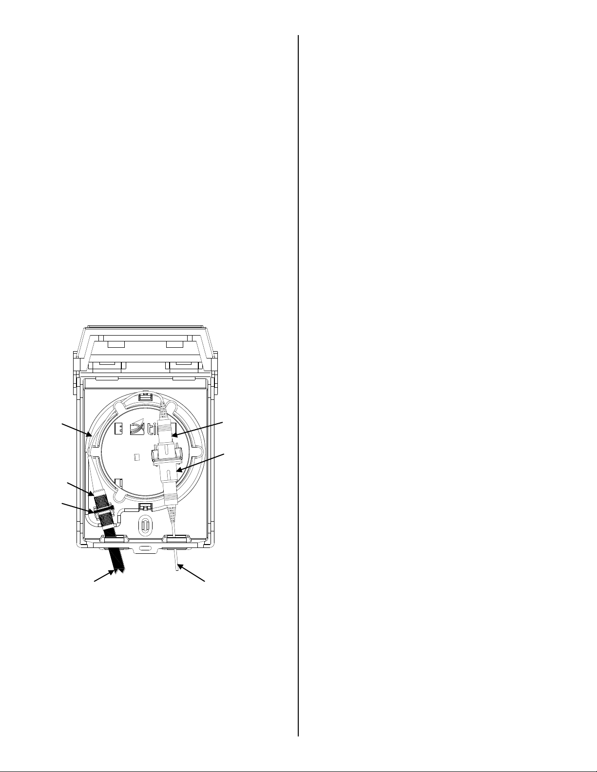
Mounting holes
Grommet
Wire Entry
Grommet
Wire Exit
Telco Entry
Grommet
Slack Tray
Fiber Optic
Interface Device
Enclosure
Customer Exit
Grommet
SC Adapter
Strain Relief for
FTTX Connector
SC Bulkhead
Installation
1. The TII 169F Fiber Optic Interface Device is a
compact fiber optic connectivity and fiber slack
storage enclosure.
2. The large split grommets located at the bottom
of the base allow Telco drop lines and
customer cables to enter and exit the device.
3. The TII 169F is supplied with SC adapters to
allow one to four fiber optic connections.
4. The slack tray allows for sufficient fiber cable
slack storage.
Features
Figure 1
1. Mount the 169F Device so as to minimize the
possibility of dirt or moisture getting into the
enclosure.
2. 169F Devices mounted side-by-side or end-toend should be placed so covers can easily be
opened.
3. Remove the slack tray from the enclosure to
expose the mounting screw locations.
4. Mount the 169F Device vertically on a flat
surface using appropriate hardware (the
length of the mounting screws should allow for
1/8” of length within the enclosure).
5. The mounting holes are covered with a thin
film of plastic, easily punched out, to maintain
the environmental integrity of the enclosure
(See Figure 2).
6. Re-install the slack tray into the enclosure and
prepare for wiring.
Figure 2
Page 2
Wiring
Tie-Wrap
FTTX
Connector
Telco Drop
Cable
Customer Out
Fiber Cable with
SC Connector
SC Adapter
Provided
Customer Fiber
Cable with SC
Slack Wire
1. Guide the Telco Drop Cable through the left
split entry grommet.
2. Using the FTTX Connector, splice the Telco
Drop Cable and the Customer Fiber Cable
together as required.
3. Install the already spliced FTTX Connector to
the slack tray strain relief using a tie-wrap.
Push the tie-wrap through the provided slots
on the slack tray, wrap over the FTTX
Connector and tighten the tie-wrap.
4. Wrap excess Customer Fiber Cable clockwise
around the slack tray.
5. Then insert the SC connector into the provided
SC Adapter.
6. Insert the SC Connector, Customer Out Fiber
Cable to the opposing side of the SC Adapter.
7. Guide the Customer Fiber Cable through the
right Customer Exit Grommet.
8. Close the cover until it snaps shut.
Figure 3
 Loading...