

Page 1

Installation Manual
TS4 UHD-Core with TAP and CCA
Page 2

IMPORTANT SAFETY INSTRUCTIONS
LETHAL VOLTAGE MAY BE PRESENT IN ANY PV INSTALLATION
SAVE THESE INSTRUCTIONS
• This manual contains important instructions for installation and maintenance of the Tigo
product models TS4-L, TS4-O, TS4-S, TS4-M, TS4-A-O, TS4-A-S, TS4-A-M, TS4-A-O-Duo, TS4-A-SDuo, TS4-A-M-Duo, TS4-R-O, TS4-R-S, TS4-R-M, TS4-R-O-Duo, TS4-R-S-Duo, TS4-R-M-Duo, Tigo
Access Point (TAP), Cloud Connect Advanced (CCA), and related Tigo software and
mobile applications.
• Risk of electric shock, do not remove cover, disassemble, or repair, no user serviceable
parts inside. Refer servicing to qualied service personnel.
• Before installing or using the Tigo System, please read all instructions and warning
markings on the Tigo products, appropriate sections of your inverter manual,
photovoltaic (PV) module installation manual, and other available safety guides.
• Failure to adhere to these instructions may result in injury or death, damage to the
system, or voiding the factory warranty.
• To reduce risk of re and shock hazard, install this device with strict adherence to
National Electric Code (NEC) ANSI/NFPA 70 and/or local electrical codes. When the
photovoltaic array is exposed to light, it supplies a DC voltage to the Tigo TS4 units. The
TS4 units start in the “ON” state and their output voltage may be as high as the PV
module open circuit voltage (VOC) when connected to the module. The installer should
use the same caution when handling electrical cables from a PV module with or without
the TS4 units attached.
• Installation must be performed by trained professionals only. Tigo does not assume
liability for loss or damage resulting from improper handling, installation, or misuse of
products.
• Remove all metallic jewelry prior to installing the Tigo TS4 units to reduce the risk of
contacting live circuitry. Do not attempt to install in inclement weather.
• Do not operate the Tigo TS4 units if they have been physically damaged. Check existing
cables and connectors, ensuring they are in good condition and appropriate in rating.
Do not operate Tigo TS4 units with damaged or substandard wiring or connectors. Tigo
TS4 units must be mounted on the high end of the PV module backsheet or racking
system, and in any case above ground.
• Do not connect or disconnect under load. Turning off the Inverter and/or the Tigo
products may not reduce this risk. Internal capacitors within the inverter can remain
charged for several minutes after disconnecting all power sources. Verify capacitors
have discharged by measuring voltage across inverter terminals prior to disconnecting
wiring if service is required. Wait 30 seconds after rapid shutdown activation before
disconnecting DC cables or turning off DC disconnect.
• Always assume TS4 units are in “ON” state, or may turn on when restarting.
• The CCA must be on the same AC branch circuit as the inverter to meet rapid shutdown
requirements.
10/02/2019
2
Page 3

TABLE OF CONTENTS
Tigo System Overview 4
TS4 Flex MLPE Versions 5
TS4 Flex MLPE Functions 6
Communication Accessories 7
System Overview: TS4-B 8
System Overview: TS4-R 9
System Overview: TS4-A 10
System Overview: TS4-A-Duo 11
MLPE Installation Notes 12
TS4-B Installation 13
TS4-R Installation 14
TS4-A Installation 15
TS4-A-Duo Installation 16
Congure Module Layout 28
Connect CCA To Smartphone 29
Congure Network Settings –
Connect CCA To Internet 30
Commission The TS4 Units –
Run Discovery 30
String Design With TS4 31
Appendix
Product Specications, Rapid Shutdown,
String Sizing with TS4-L 32
Technical Specications –
Smart Module with TS4-B 33
Technical Specications – TS4-R 34
Technical Specications – TS4-A 35
Technical Specications – TS4-R-Duo 36
Communication Installation 17
TAP Installation Mesh Conguration 18
TAP Placement Example - Mesh 19
CCA Installation 20
CCA LED Status Guide 21
CCA & TAP Wiring 22
Modbus RS-485 Wiring Diagram
& Conguration Template 23
Conguration, Registration,
& Commissioning 24
Tigo SMART App 25
Getting Started 26
Select Equipment 27
Technical Specications – TS4-A-O-Duo 37
Technical Specications –
CCA & TAP 38
Testing Rapid Shutdown 39
String Sizing With TS4-L 40
TAP Placement - Legacy (Pre-Mesh) 41
Installation Complete 42
3
Page 4
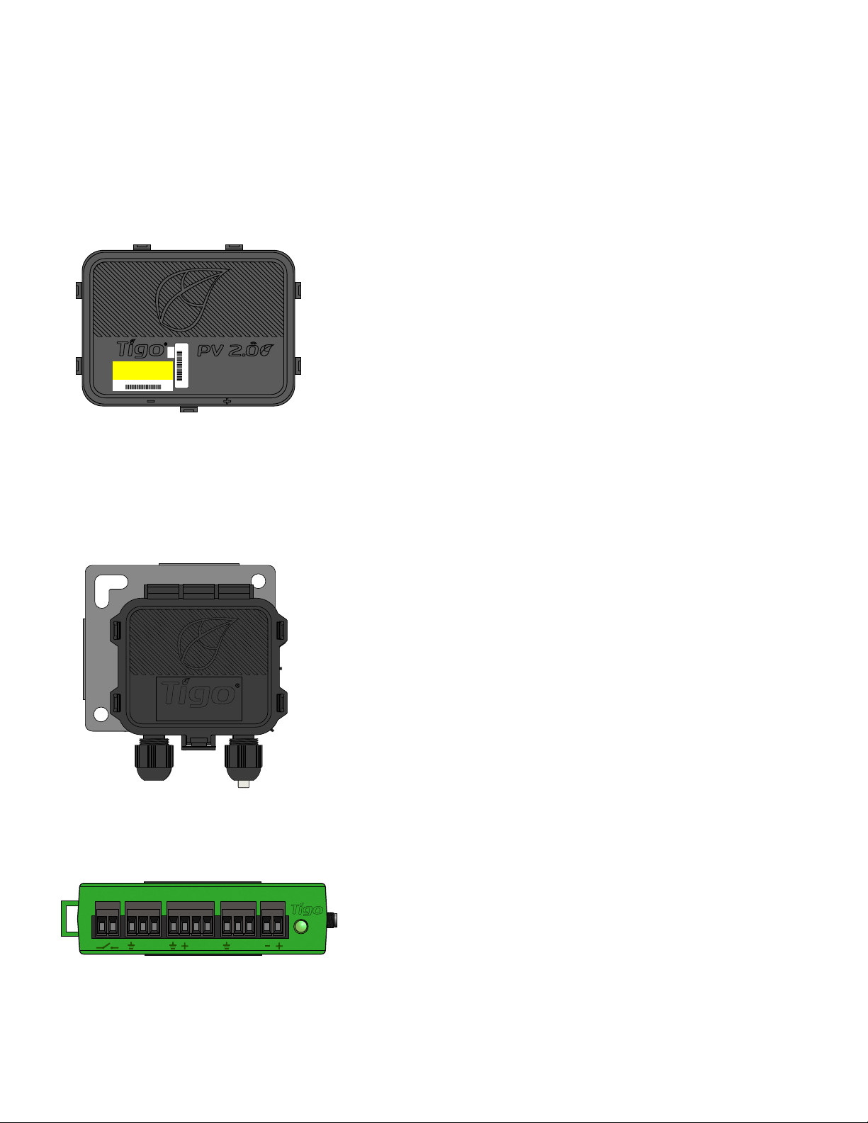
TIGO SYSTEM OVERVIEW
Module Level Power Electronics:
TS4
Modular smart electronics platform
TS4 - O
4-1234T
Communication Accessories:
4-1234T
access point
AUX RS485-1 RS485-2GATEWAY POWER
B A B A B A
Tigo Access Point
(TAP)
Wireless communication device for
monitoring and safety features
Cloud Connect
Advanced (CCA)
Data logger and rapid shutdown
control
4
Page 5
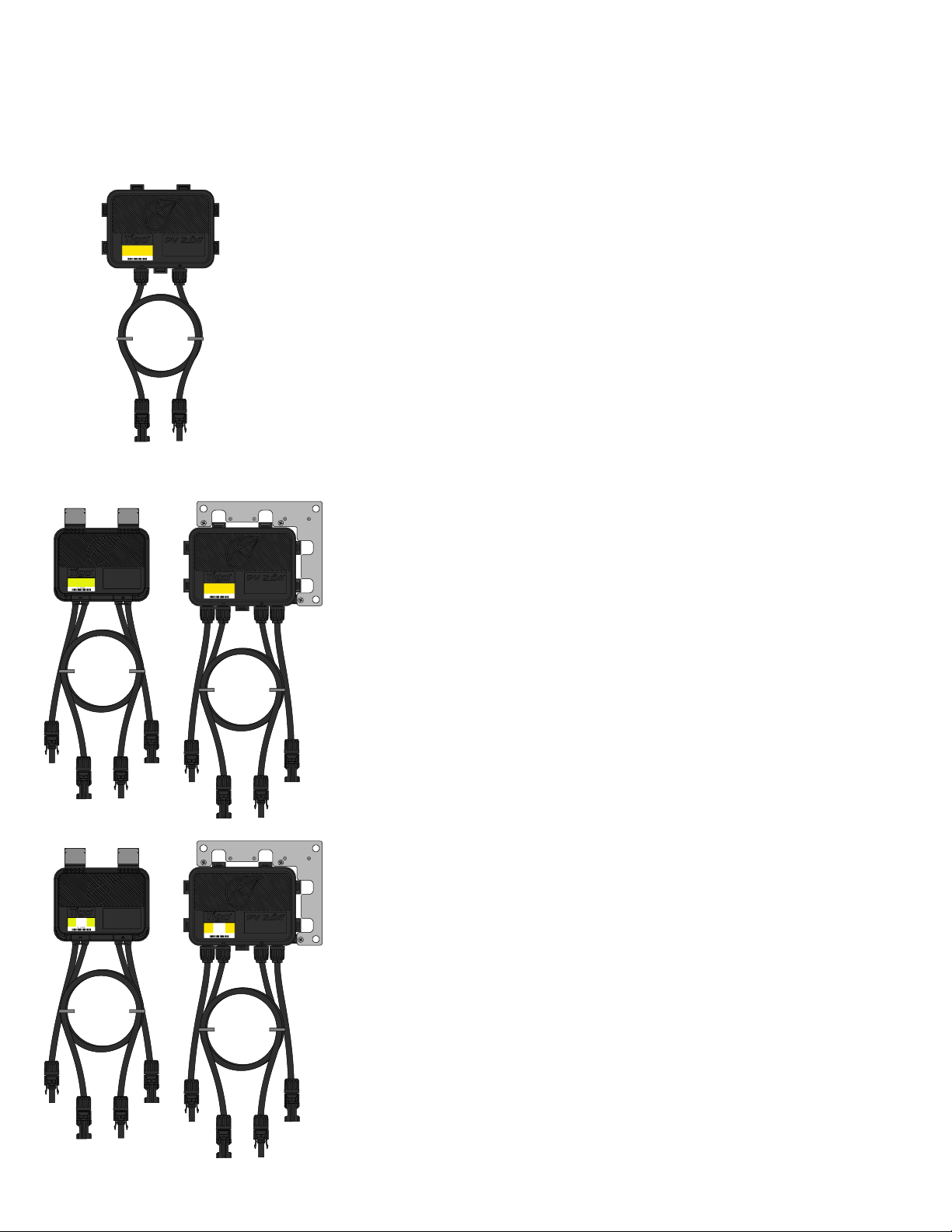
TS4 FLEX MLPE VERSIONS
4- 123A
4- 123A
TS4-B
TS4-O
4- 123A
• Module electronics are contained in the
junction box, installed at the PV module
factory
• Connected in series like regular modules
• No additional wiring connections to make
TS4-A, TS4-R
TS4-A-O
TS4-R-O
4- 123A
• Bracket clips to module frame without tools
• TS4-R outputs are connected in series
to form a string
• No additional grounding required
TS4-A-Duo, TS4-R-Duo
TS4-A-O-Duo
TS4-R-O-Duo
4- 123A
• Bracket clips to module frame without tools
• Designed to fit two 60 cell modules in series
to one TS4-A-Duo or TS4-R-Duo
• TS4-A-Duo or TS4-R-Duo outputs are
connected in series to form a string
• No additional grounding required
5
Page 6
TS4 FLEX MLPE FUNCTIONS
The TS4 Flex MLPE platform is incremental in functionality.
Select the TS4 version with features that best address the
needs of your project.
MONITORING
TS4-M
Diodes Monitoring
• Reduced O&M costs
• PV-2.0 data synchronization
• Module bar code tracking
SAFETY
TS4-S
• CRM integration
• Warranty tracking
• Fleet management
• NEC 2014 & 2017 690.12 rapid shutdown
compliant
• Module-level deactivation
OPTIMIZATION
TS4-O
• Shade and mismatch tolerance
• Enhanced energy yield
• Greater design exibility
LONG STRINGS
TS4-L
• String length increased by up to 30%
• Fewer BOS components
• Faster installation
Diodes Monitoring Safety
• Automatic or manual shutdown
• Plus all the benets of Monitoring
Diodes
• Maximized roof usage
• Plus all the benets of Safety and Monitoring
• Inverter optimization
• Lower wire-losses
• Plus all the benets of Optimization, Safety,
and Monitoring
Monitoring Safety
SafetyDiodes
Optimization
OptimizationMonitoring
Long Strings
For the TS4-F (Fire Safety) manual, click here
6
Page 7
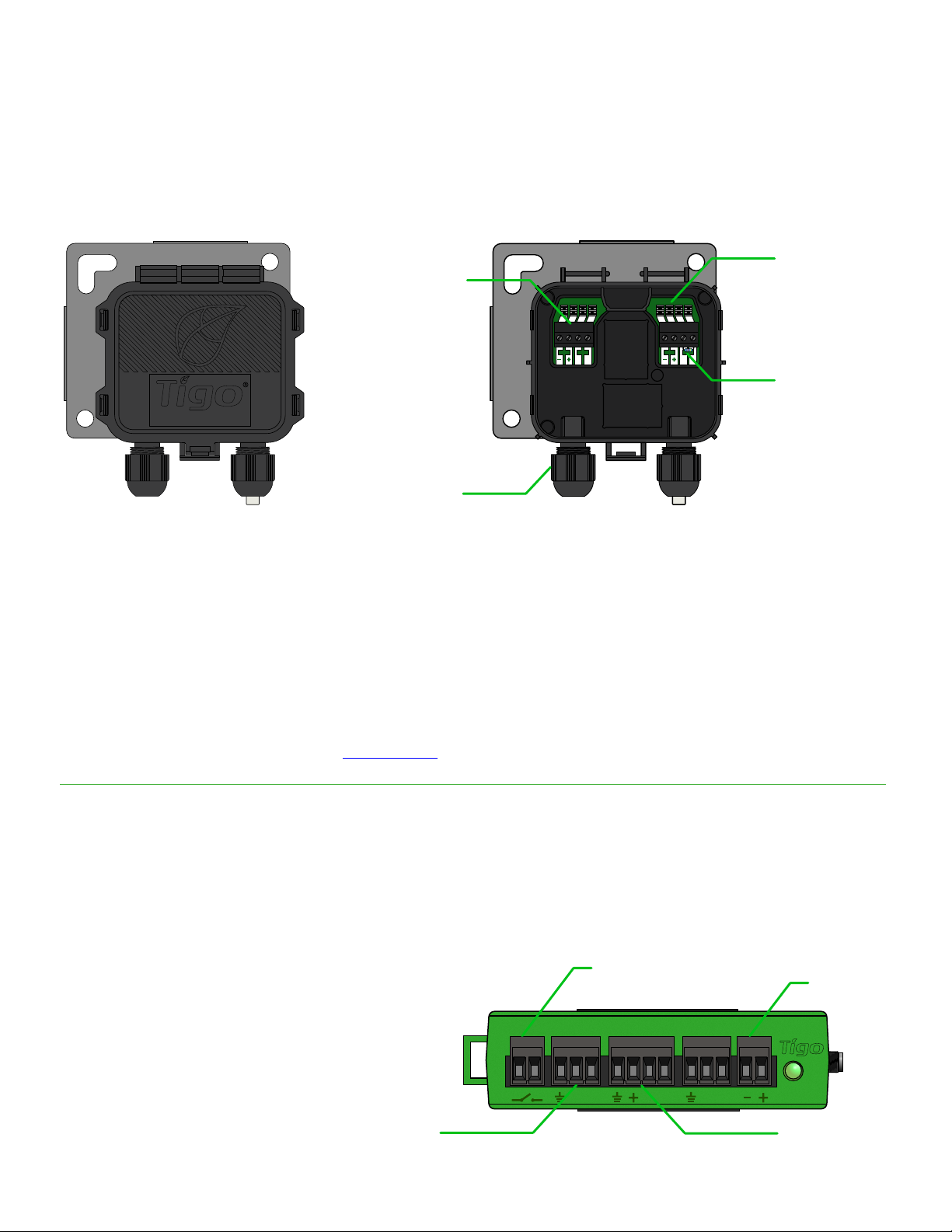
COMMUNICATION ACCESSORIES
Tigo Access Point (TAP)
access point
Mesh configuration:
• 300 TS4 units per TAP
• 900 TS4 units per CCA
• 7 TAPs per CCA
RS485
terminal
block
Cable
gland
Quick
connect
PWR PWRDATA DATA
B BA A
120Ω
resistor
Wireless range:
• 33ft (10m) max between TAP and
closest TS4 unit
• 115ft (35m) max between TAP and
farthest TS4 unit using mesh
Legacy configuration:
• Same as Gateway, see appendix for more details
Cloud Connect Advanced (CCA)
• CCA is required for monitoring
and rapid shutdown
• CCA is optional for optimization
and long strings
• Install near inverter with access
to AC power and internet
• Ethernet and Wi-Fi
are built-in
RS485 port for
3rdparty devices
AUX RS485-1 RS485-2GATEWAY POWER
Connector for
external switch
(optional)
B A B A B A
DC power
input
TAP/GTWY
7
Page 8
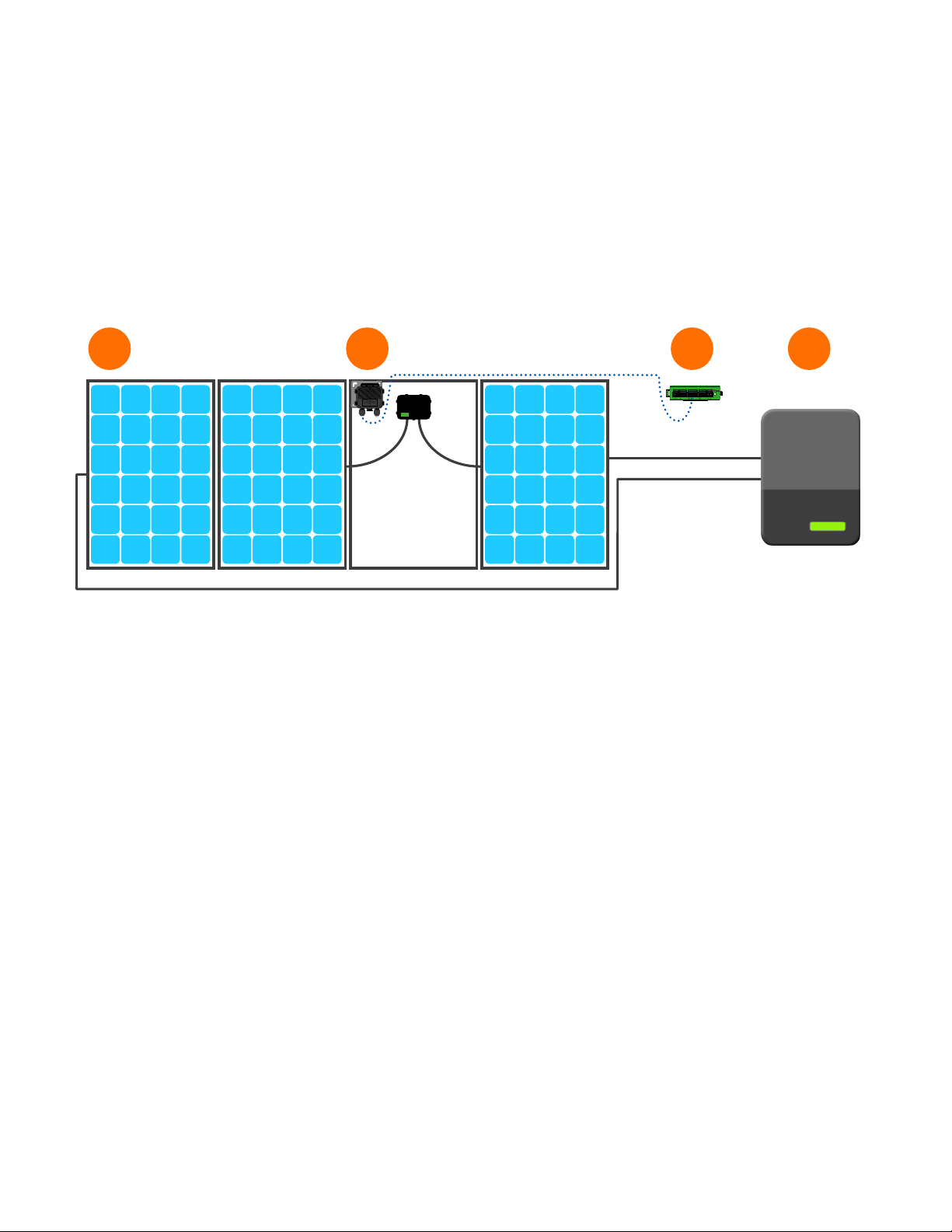
SYSTEM OVERVIEW: TS4-B
1 2 43
accesspoint
AUX RS485-1 RS485-2GATEWAY POWER
B A B A BA
1. Modules with integrated TS4
2. Tigo Access Point (TAP)
3. Cloud Connect Advanced (CCA)
4. Inverter
8
Page 9
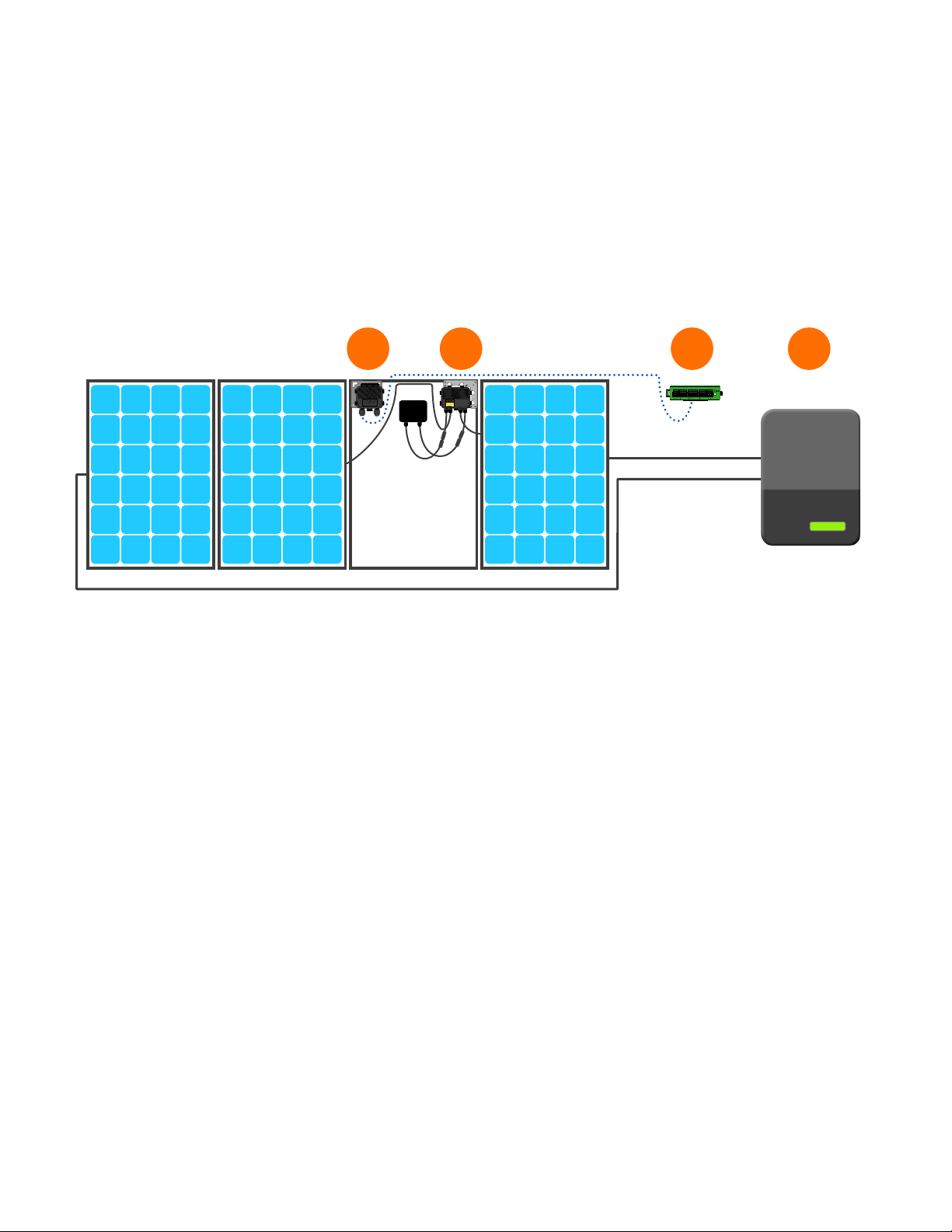
SYSTEM OVERVIEW: TS4-R
1 2 43
TS4-R-O
accesspoint
4-123A
AUX RS485-1 RS485-2GATEWAY POWER
B A B A BA
1. Tigo Access Point (TAP)
2. TS4-R installed on standard module
3. Cloud Connect Advanced (CCA)
4. Inverter
Note: connect modules to TS4-R inputs before connecting outputs
• TS4-R mounting is recommended on the upper right as shown, but can
be placed on upper left if needed (due to racking constraints, etc.)
• TS4-R cable glands must not be facing up
• Allow clearance between PV module and mounting surface for air
circulation around TS4-R
• Do not drill additional mounting holes in the frame or metal bracket
9
Page 10
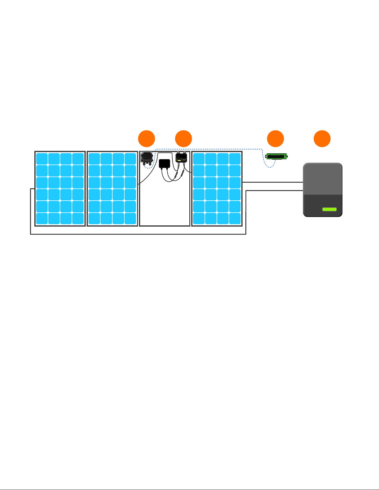
SYSTEM OVERVIEW: TS4-A
1 2 43
TigoRapidShutdown
NEC690.12-2017andC22.1-2015Rule64.218
DONOTDISCONNECT
TS4-A-O
UNDERLOAD
accesspoint
4-123A
AUX RS485-1 RS485-2GATEWAY POWER
B A B A BA
1. Tigo Access Point (TAP)
2. TS4-A installed on standard module
3. Cloud Connect Advanced (CCA)
4. Inverter
Note: connect modules to TS4-A inputs before connecting outputs
• TS4-A mounting is recommended on the upper right as shown, but can
be placed on upper left if needed (due to racking constraints, etc.)
• TS4-A cable glands must not be facing up
• Allow clearance between PV module and mounting surface for air
circulation around TS4-A
• Do not drill additional mounting holes in the frame or metal bracket
10
Page 11
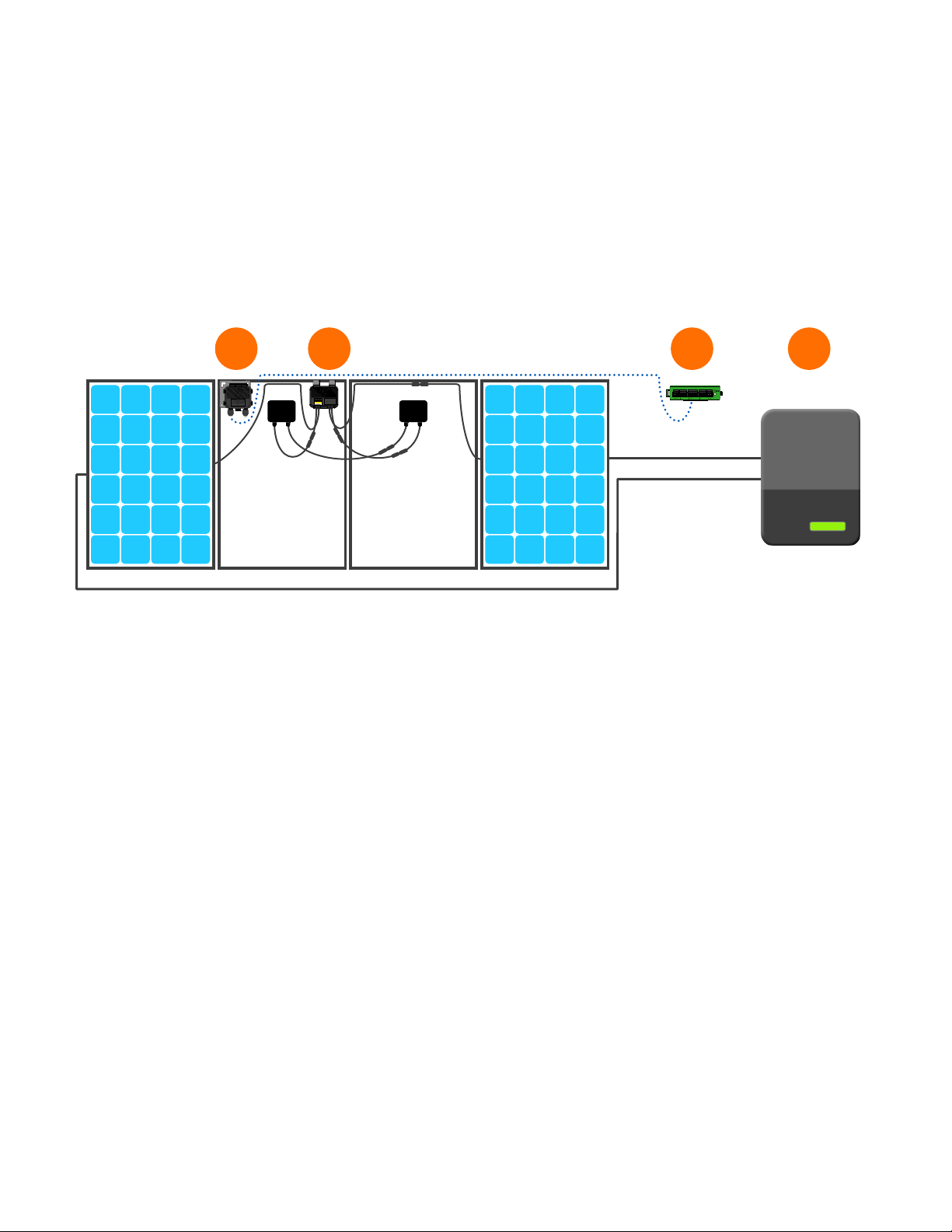
SYSTEM OVERVIEW: TS4-A-DUO
1 2 43
AUX RS485-1 RS485-2GATEWAY POWER
TigoRapidShutdown
NEC690.12-2017andC22.1-2015Rule64.218
DONOTDISCONNECT
TS4-A-O
UNDERLOAD
accesspoint
4-123A
B A B A BA
1. Tigo Access Point (TAP)
2. TS4-A-O-Duo installed on pair of standard modules
(modules are connected in series to TS4 inputs)
3. Cloud Connect Advanced (CCA)
4. Inverter
Note: connect modules to TS4-A inputs before connecting outputs
• TS4-A mounting is recommended on the upper right as shown, but can
be placed on upper left if needed (due to racking constraints, etc.)
• TS4-A cable glands must not be facing up
• Allow clearance between PV module and mounting surface for air
circulation around TS4-A
• Do not drill additional mounting holes in the frame or metal bracket
11
Page 12
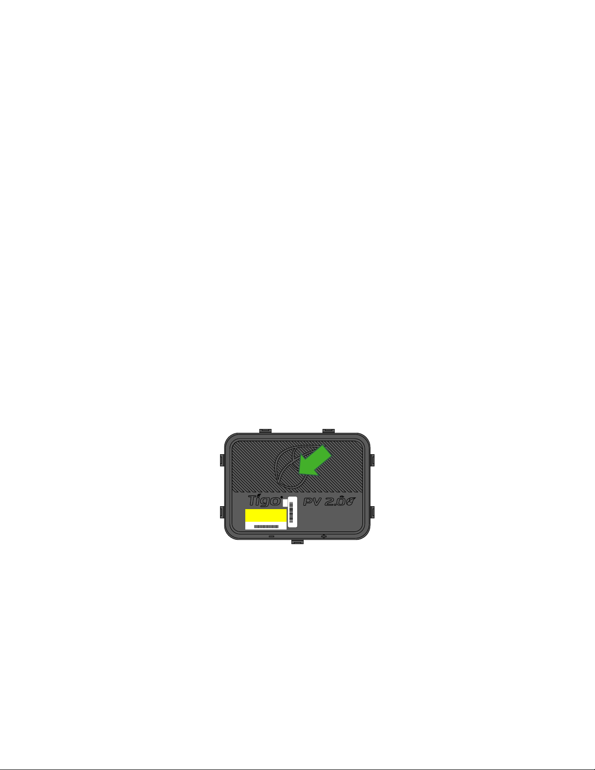
MLPE INSTALLATION NOTES
• Note: The following TS4 products are shipped in the ON
position:
• TS4-M, TS4-S, TS4-O, TS4-L
• TS4-A-O, TS4-A-O-Duo
• TS4-R-M, TS4-R-S, TS4-R-O
• TS4-R-M-Duo, TS4-R-S-Duo, TS4-R-O-Duo
• Upon exposure of the PV module to sunlight high voltage is
present. Handle with the appropriate precautionary
measures.
• Optimization and Long Strings features don’t require
communication accessories in order to work.
• To enable Monitoring and Safety features:
• Collect the TS4 removable barcode label from the PV module
junction box.
TS4 - O
4-1234T
• Install and commission communication accessories.
4-1234T
With add-on units, failing to follow the sequence of installation steps
may result in TS4 damage not covered under warranty.
12
Page 13
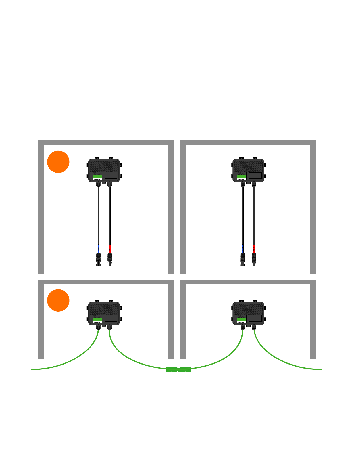
TS4-B INSTALLATION
Smart modules with an integrated TS4 junction box are installed and
connected in series just like standard PV modules.
No additional grounding is required for the TS4 units.
1
TS4-L
4-123A
TS4-L
4-123A
2
TS4-L
4-123A
TS4-L
4-123A
13
Page 14
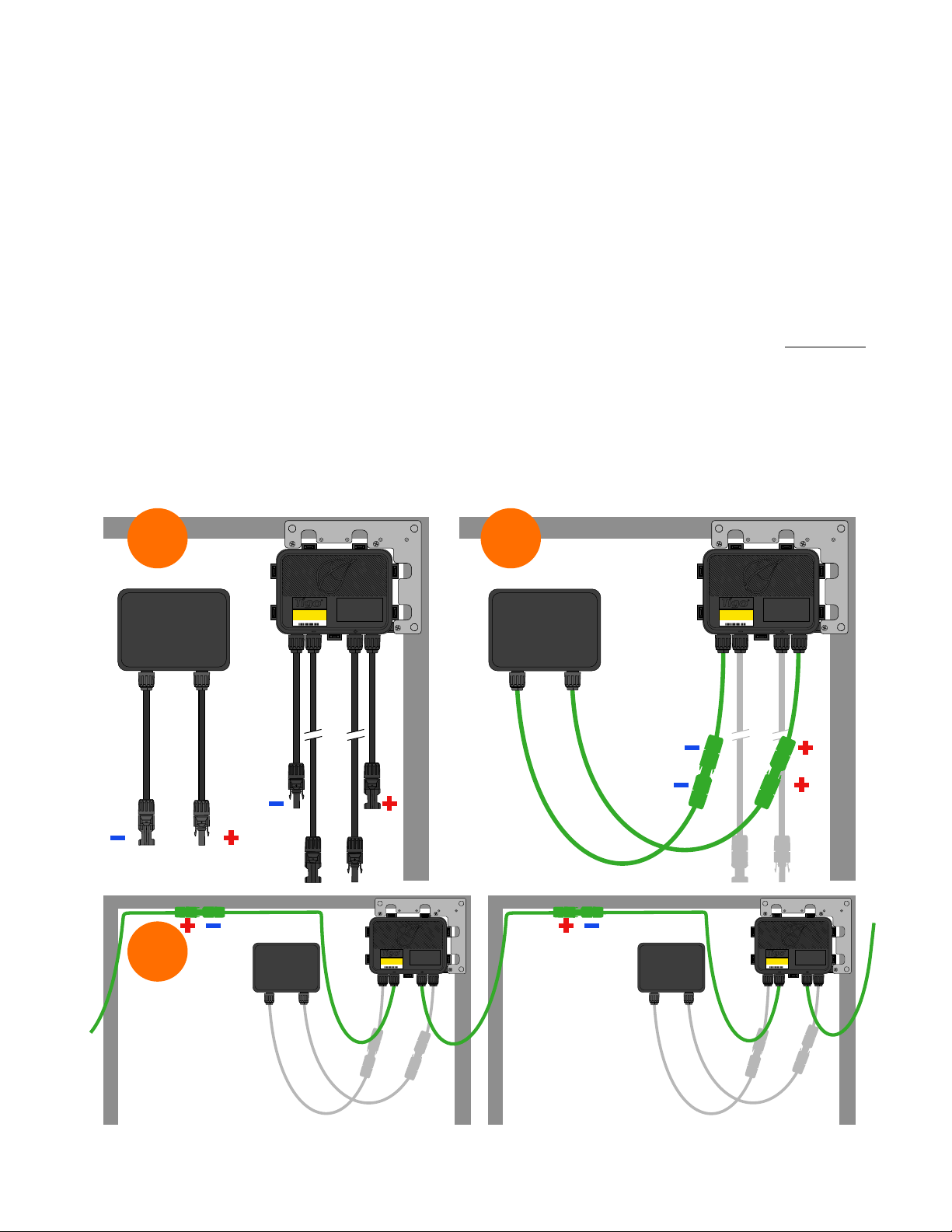
TS4-R INSTALLATION
Standard modules can be equipped with TS4-R add-on units as
shown below.
Always connect modules to TS4-R inputs before connecting outputs.
Each TS4-R must have a PV module connected to its inputs before
connecting the outputs of TS4-R units in series.
To disconnect TS4-R from a module, disconnect the TS4-R outputs
from the string before disconnecting the TS4-R inputs from the
module junction box.
1
3
TS4-R-O
4- 123A
TS4-R-O
2
TS4-R-O
4- 123A
4-123A
TS4-R-O
4-123A
14
Page 15
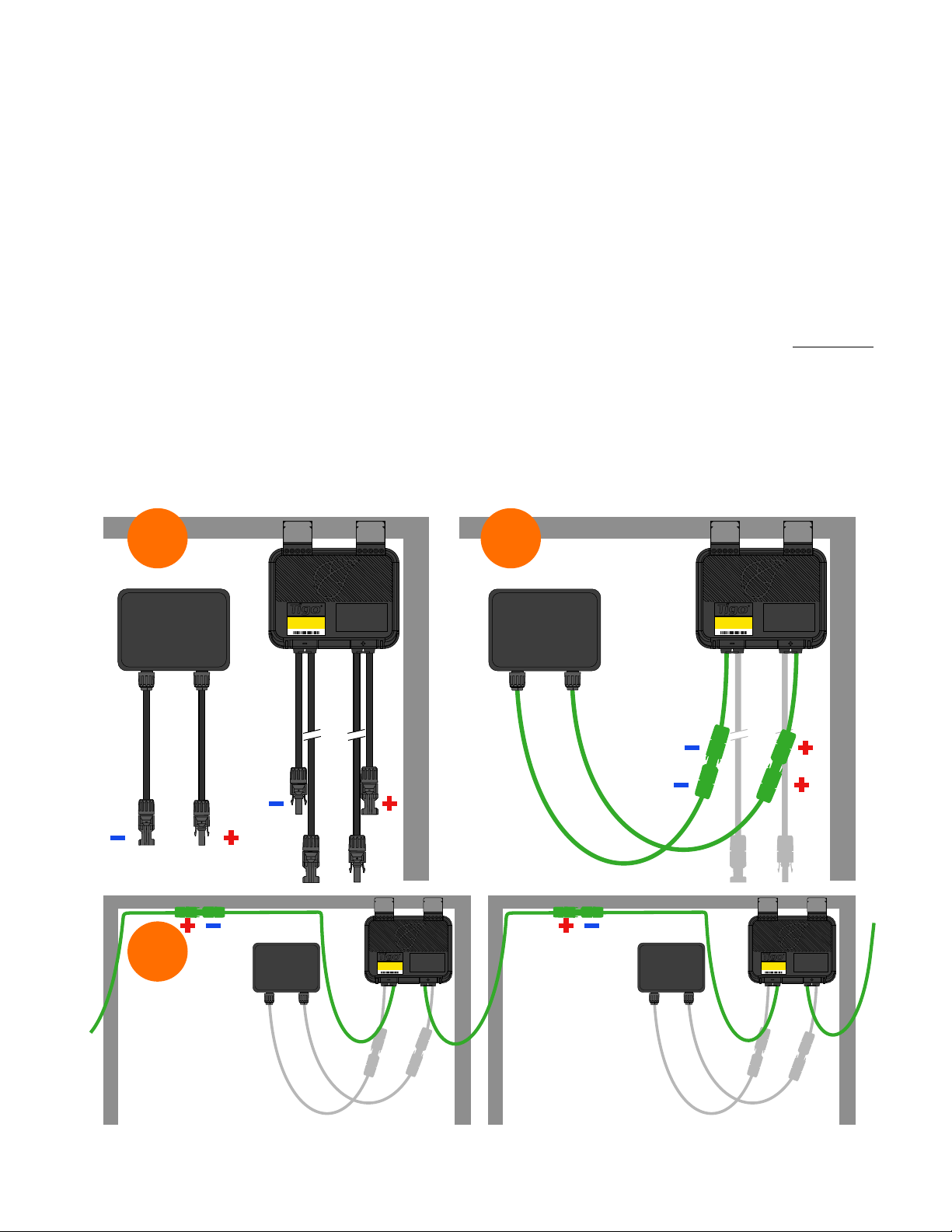
TS4-A INSTALLATION
Standard modules can be equipped with TS4-A add-on units as
shown below.
Always connect modules to TS4-A inputs before connecting outputs.
Each TS4-A must have a PV module connected to its inputs before
connecting the outputs of TS4-A units in series.
To disconnect TS4-A from a module, disconnect the TS4-A outputs
from the string before disconnecting the TS4-A inputs from the
module junction box.
1 2
3
TS4-A-O
4- 123A
TigoRapid Shutdown
NEC690.12-2017andC22.1-2015Rule64.218
DONOTDISCONNECT
UNDERLOAD
TS4-A-O
4- 123A
TigoRapidShutdown
NEC690.12-2017andC22.1-2015Rule64.218
TigoRapid Shutdown
NEC690.12-2017andC22.1-2015Rule64.218
TS4-A-O
4- 123A
DONOTDISCONNECT
UNDERLOAD
TS4-A-O
4- 123A
DONOTDISCONNECT
UNDERLOAD
TigoRapidShutdown
NEC690.12-2017andC22.1-2015Rule64.218
DONOTDISCONNECT
UNDERLOAD
15
Page 16
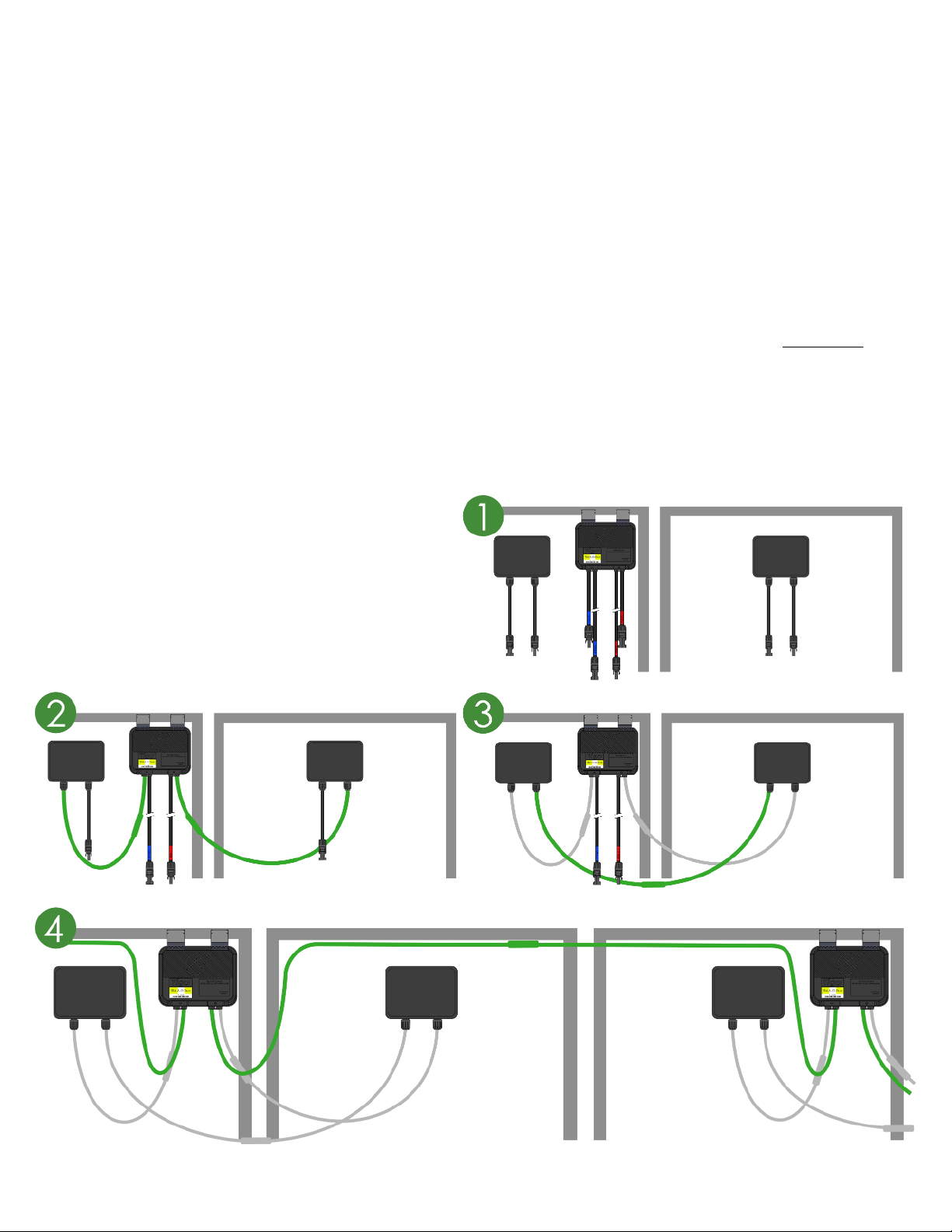
TS4-A-DUO INSTALLATION
Standard modules can be equipped with TS4-A-Duo add-on units
as shown below.
Always connect modules to TS4-A inputs before connecting outputs.
TS4-A-Duo must have a PV module connected to its inputs before
connecting the outputs of TS4-A-Duo units in series.
To disconnect TS4-A-Duo from a module, disconnect the TS4-A-Duo
outputs from the string before disconnecting the TS4-A-Duo inputs
from the module junction box.
16
Page 17

COMMUNICATION INSTALLATION
COMMUNICATION DESIGN RULES
• MESH CONFIGURATION
• 300 TS4 units per TAP
• 900 TS4 units per CCA
• 7 TAPs per CCA
• 33ft (10m) max between TAP and closest TS4 unit
• 115ft (35m) max wireless range using mesh
• No more than 10m between TS4 units on same TAP
• LEGACY CONFIGURATION
• 120 TS4 units per TAP
• 360 TS4 units per CCA
• 7 TAPs per CCA
• 50ft (15m) radius with line of sight between TAP & all TS4 units
Wireless signal range can be affected by solid obstructions. Refer to
TAP Placement Guide for more information.
NOTES
• All TS4 units in the same string must be assigned to the same CCA.
• For further design information, click here.
CCA and TAP CALCULATOR
• To estimate the number of CCAs and TAPs required for your
project, click here.
17
Page 18
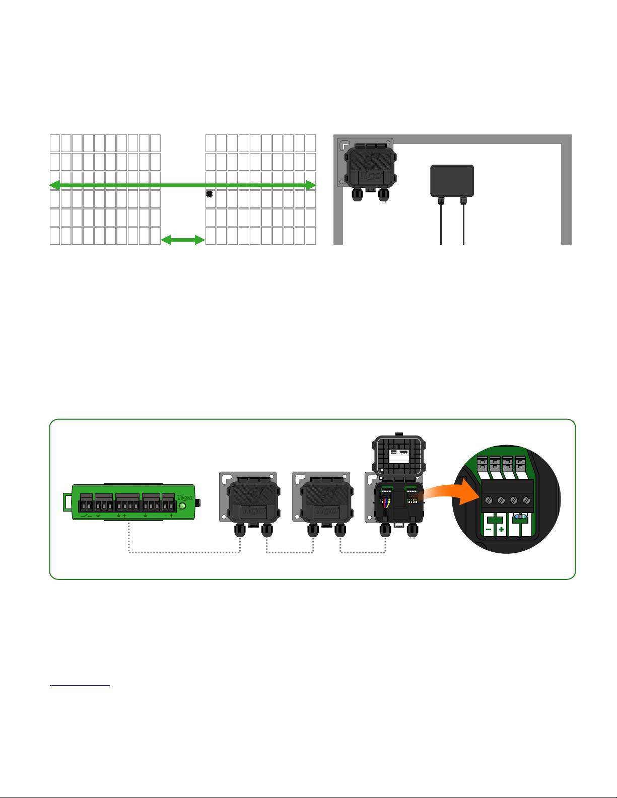
TAP INSTALLATION -
PWR DATA
B A
MESH CONFIGURATION
accesspoint
230ft (70m) max
33ft (10m) max
access point
Place TAP within 10m of any TS4 unit in the
array, with a maximum distance of 10m
between TS4 units and 35m from TAP to
farthest TS4.
AUX RS485-1 RS485-2GATEWAY POWER
B A B A B A
access point access point
TAP attaches to module frame using
built-in bracket. Mounting holes are
also available in case of frameless
modules.
OR
Quickconnectors:
Connectorblocks:
presswireinto terminal
usescrewterminals
Removeresistor to connect
anotherAccess Point in series.
IN OUT
-
A
B
+
P/N:158-20000-00
TigoAccessPoint (TAP)
FCCID:XNNSILICONAIR2
Patented,DesignedinUSA, Assembledin China
ICID:11021A-XNNSILICONAIR2
OperatingVoltage:
Thisproductcontainsa wirelessmodule inside.
24VDC
NEMA3RIP68
FlexMLPE
TechnicalSupport:
www.tigoenergy.com
USAtoll-free+1.844.805.8550
Allother+1.408.402.0802
EUROPE(Chat)+39.342.67.92.285
PWR PWRDATA DATA
B BA A
Connect multiple TAP units in series and leave terminating resistor in final TAP only.
Use 4-conductor RS485 (18-22 AWG) cable between TAP and CCA.
Click here for more information on TAP placement.
18
Page 19
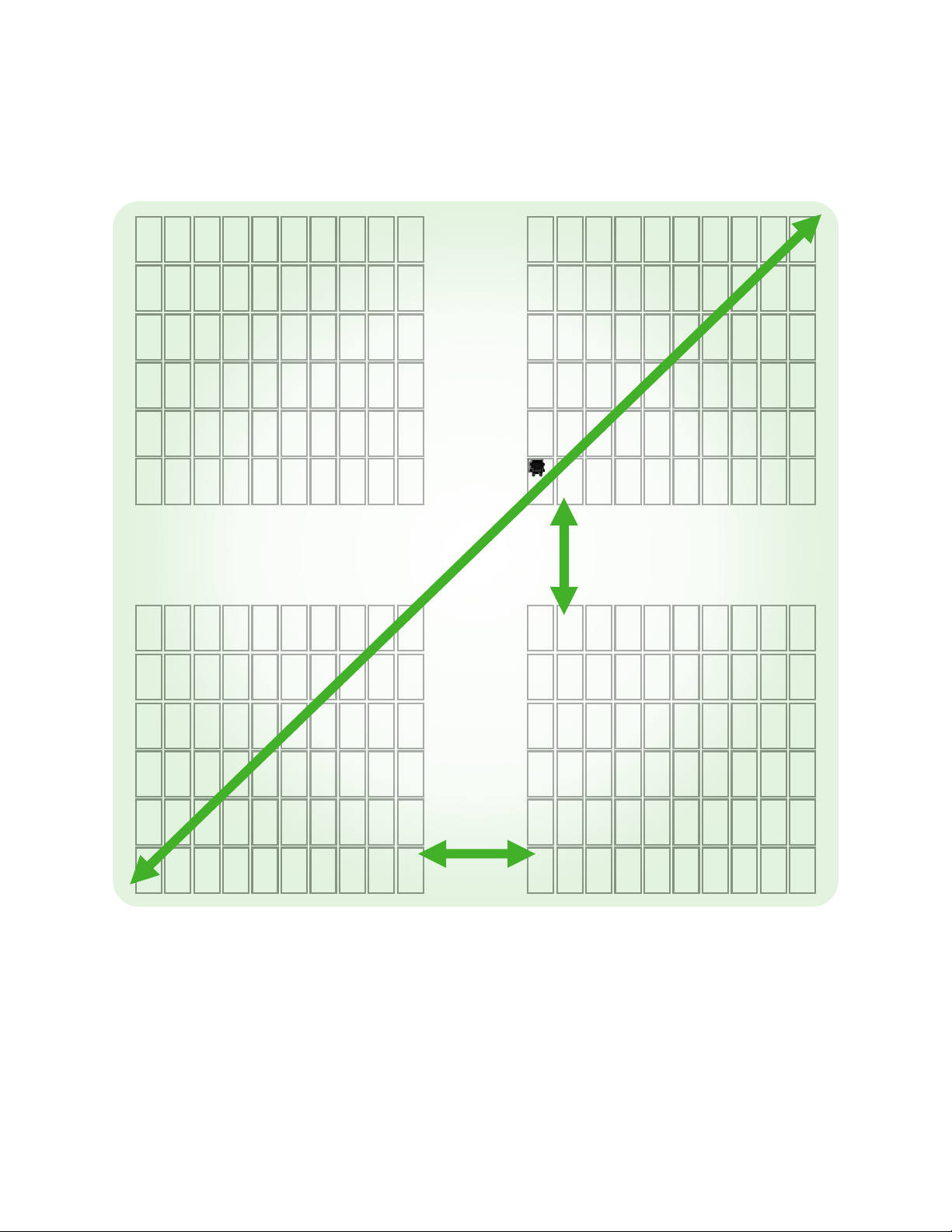
TAP PLACEMENT EXAMPLE - MESH
230ft (70m) max
accesspoint
33ft (10m) max
33ft (10m) max
Place TAP within 10m of any TS4 unit in the array.
Maximum distance of 10m between TS4 units that belong to a single TAP.
Maximum distance of 35m (115ft) between TAP and farthest TS4 unit.
Connect multiple TAPs in series for larger arrays.
19
Page 20
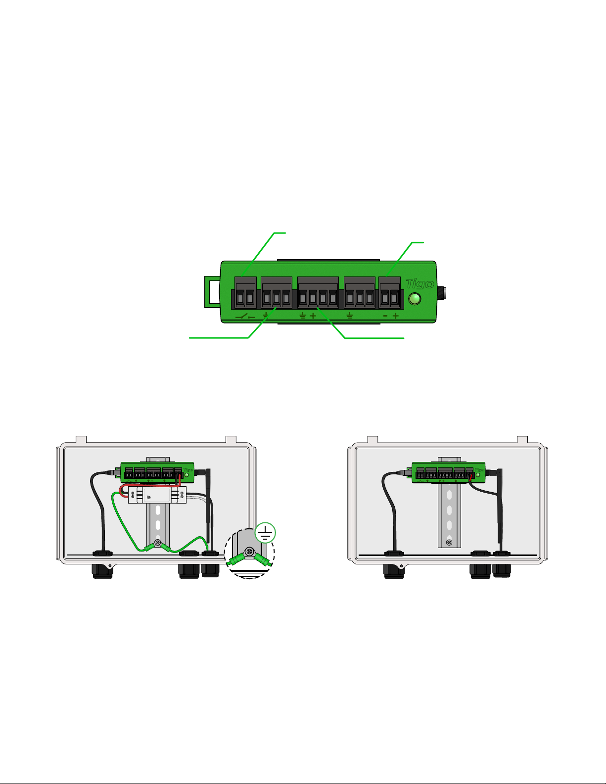
CCA INSTALLATION
• CCA is required for monitoring and rapid shutdown
• Optional for optimization and long strings
• Install near inverter with access to AC power and internet
• Ethernet and Wi-Fi are built-in
Connector for
external switch
(optional)
AUX RS485-1 RS485-2GATEWAY POWER
B A B A B A
RS485 port for
3rdparty devices
DC power
input
TAP/GTWY
CCA and TAP are required for Rapid Shutdown control
Install CCA on same AC main service as inverter for automatic activation in case of AC grid loss
AUX RS485-1 RS485-2GATEWAY POWER
B A B A B A
-
N
0.88A
+
50/60Hz
100-240VAC
+VADJ
+
L
AUX RS485-1 RS485-2GATEWAY POWER
B A B A B A
CCA with DC transformerCCA with DIN rail power supply
• Connect DC leads from power supply to
CCA
• Connect AC and DC ground wires to DIN rail
• Connect AC power input to power supply
• Connect DC leads from power
supply to CCA
Complete TAP wiring connections before powering on CCA
20
Page 21
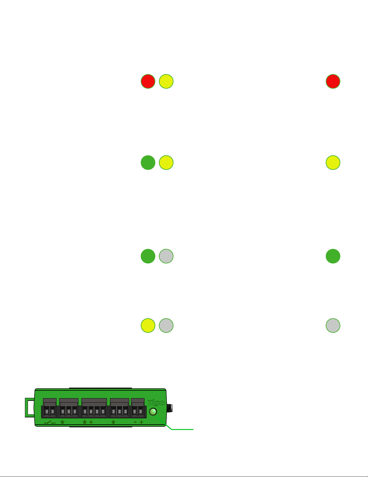
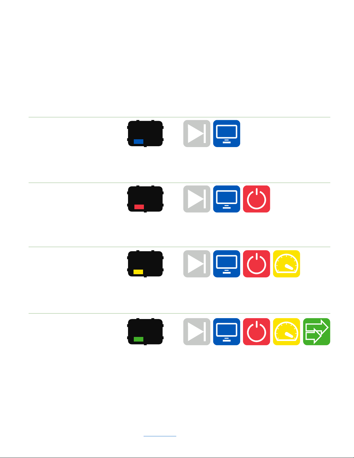
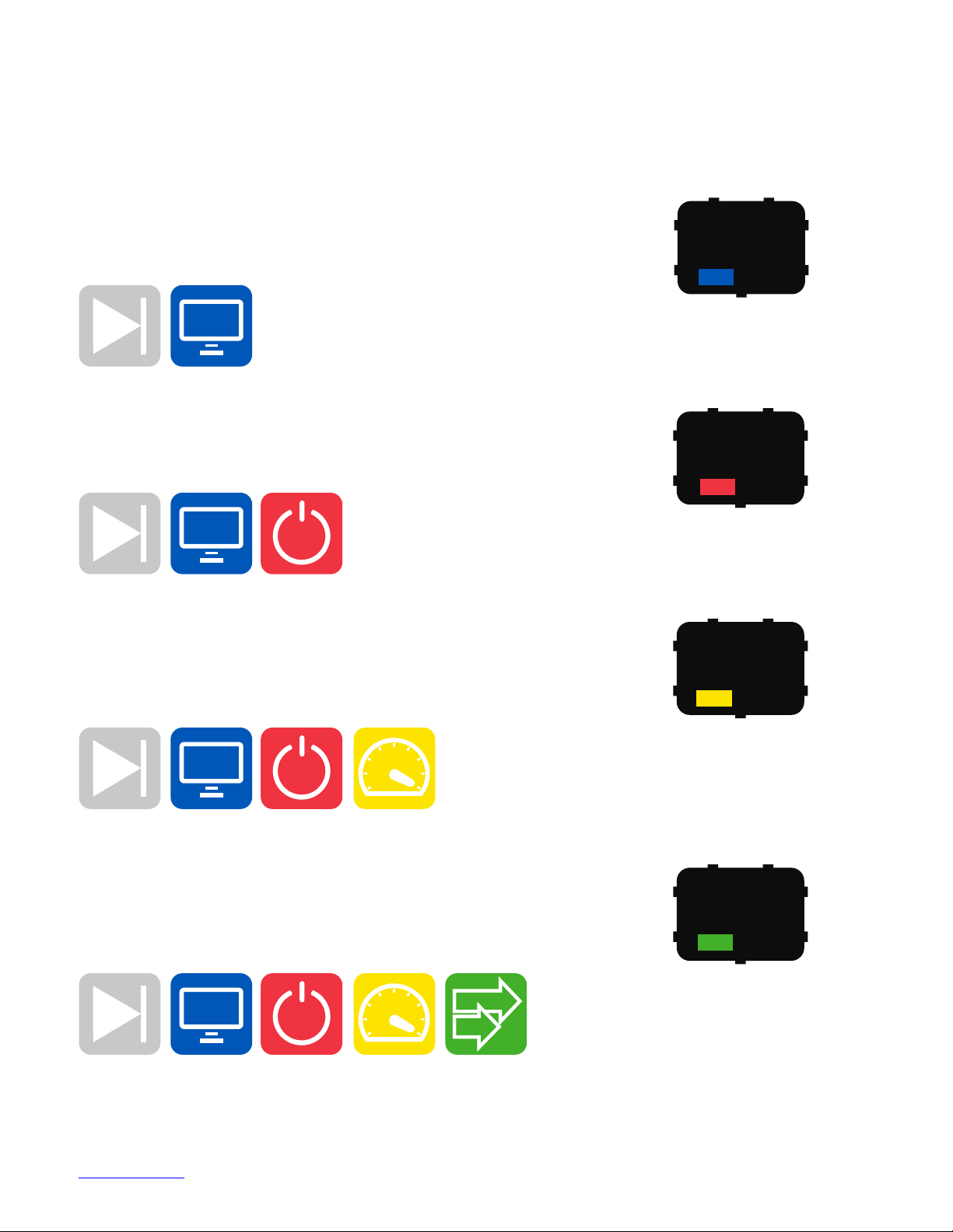
CCA LED STATUS GUIDE
Auto PV-Off Error
• A blinking red and yellow LED
indicates that the system
automatically entered PV-Off mode.
• A solid red LED indicates that the
Discovery process failed or that the
CCA is not able to connect to the
Tigo server. In case of errors,
connect to the CCA using the
mobile app for more details.
User PV-Off Warning
• A blinking green and yellow LED
indicates that PV-Off mode was
activated manually.
• A solid yellow LED indicates that:
Discovery has not been run,
Discovery completed but did not
find all expected TAPs or TS4 units, or
CCA is not able to upload data.
Connect to the CCA using the Tigo
SMART app for more details.
SMART App Activity System OK
• A blinking green LED indicates that
the mobile app is connected to the
CCA and is actively in use.
• A solid green LED indicates that
Discovery is complete and found all
expected TAPs and TS4 units, and
CCA is able to connect to the Tigo
server.
Discovery Power Off / No Status
• A blinking yellow LED indicates that
the CCA is scanning for TAPs and TS4
units (part of the commissioning
process).
AUX RS485-1 RS485-2GATEWAY POWER
B A B A B A
• An unlit LED indicates that the CCA
is powered off.
Status LED
21
Page 22
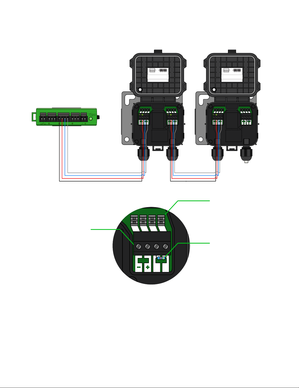
CCA & TAP WIRING
PWR DATA
B A
-
+ B A
AUX RS485-1 RS485-2GATEWAY POWER
B A B A B A
OR
Quickconnectors:
Connectorblocks:
presswire into terminal
usescrew terminals
Remove resistor to connect
another Access Point in series.
IN OUT
-
A
B
+
B A B A B A
PWR PWRDATA DATA
B BA A
OR
Quickconnectors:
Connectorblocks:
presswire into terminal
usescrew terminals
Remove resistor to connect
another Access Point in series.
IN OUT
-
A
B
+
PWR PWRDATA DATA
B BA A
Quick connect
terminals
Terminal
block
120Ω
resistor
Connect multiple TAP units in series and leave terminating resistor only
in final TAP.
If using the quick connectors, remove the terminal block from the TAP
and strip approximately 3cm of insulation from the end of the cable.
Use a small flathead screwdriver to press the conductors into the quick
connectors. The individual conductors do not require stripped ends.
Connect all communication cables before powering on CCA.
22
Page 23
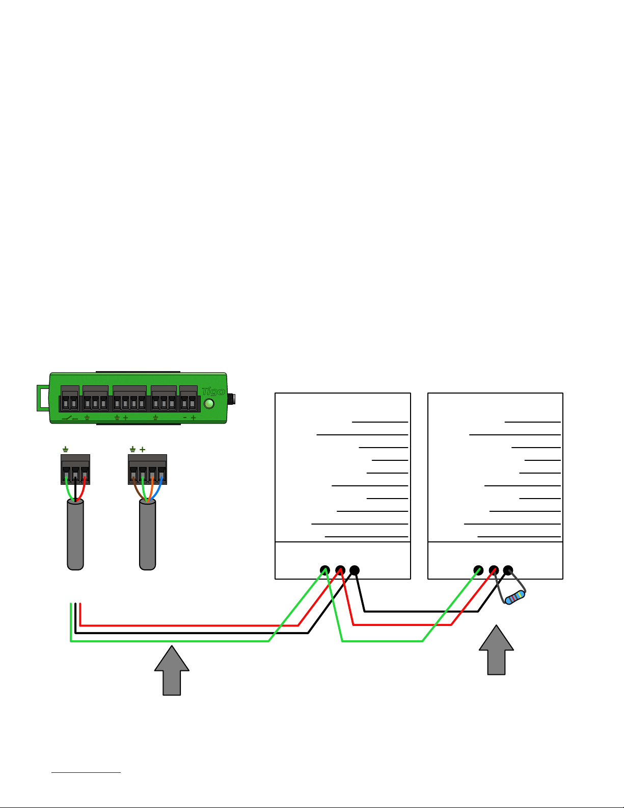
MODBUS RS-485 WIRING DIAGRAM
& CONFIGURATION TEMPLATE
• Up to 32 Modbus RS-485 devices can be
connected to a single Cloud Connect/CCA
• All devices must have a unique Modbus address
• All devices connected in series must have the same
baud rate, parity, and stop bit settings
• Check device manual for Modbus settings
Cloud Connect Advanced
(CCA)
AUX RS485-1 RS485-2GATEWAY POWER
B A B A B A
B A
To Modbus
Device(s)
B A
To TAP(s)/
Gateway(s)
Modbus Device #1
Manufacturer:
Model:
Type of Device:
Electrical Voltage:
Single or 3 Phase:
CT Rating:
Modbus Address:
Baud Rate:
Parity:
Stop Bits:
RS-485 Modbus terminal RS-485 Modbus terminal
G G+ +
- -
Modbus Device #2
Manufacturer:
Model:
Type of Device:
Electrical Voltage:
Single or 3 Phase:
CT Rating:
Modbus Address:
Baud Rate:
Parity:
Stop Bits:
120Ω resistor across + and - terminals
on the last Modbus device in series
RS-485 communication cable with shield
Click here for more info about setting up inverters, meters, & sensors
23
Page 24
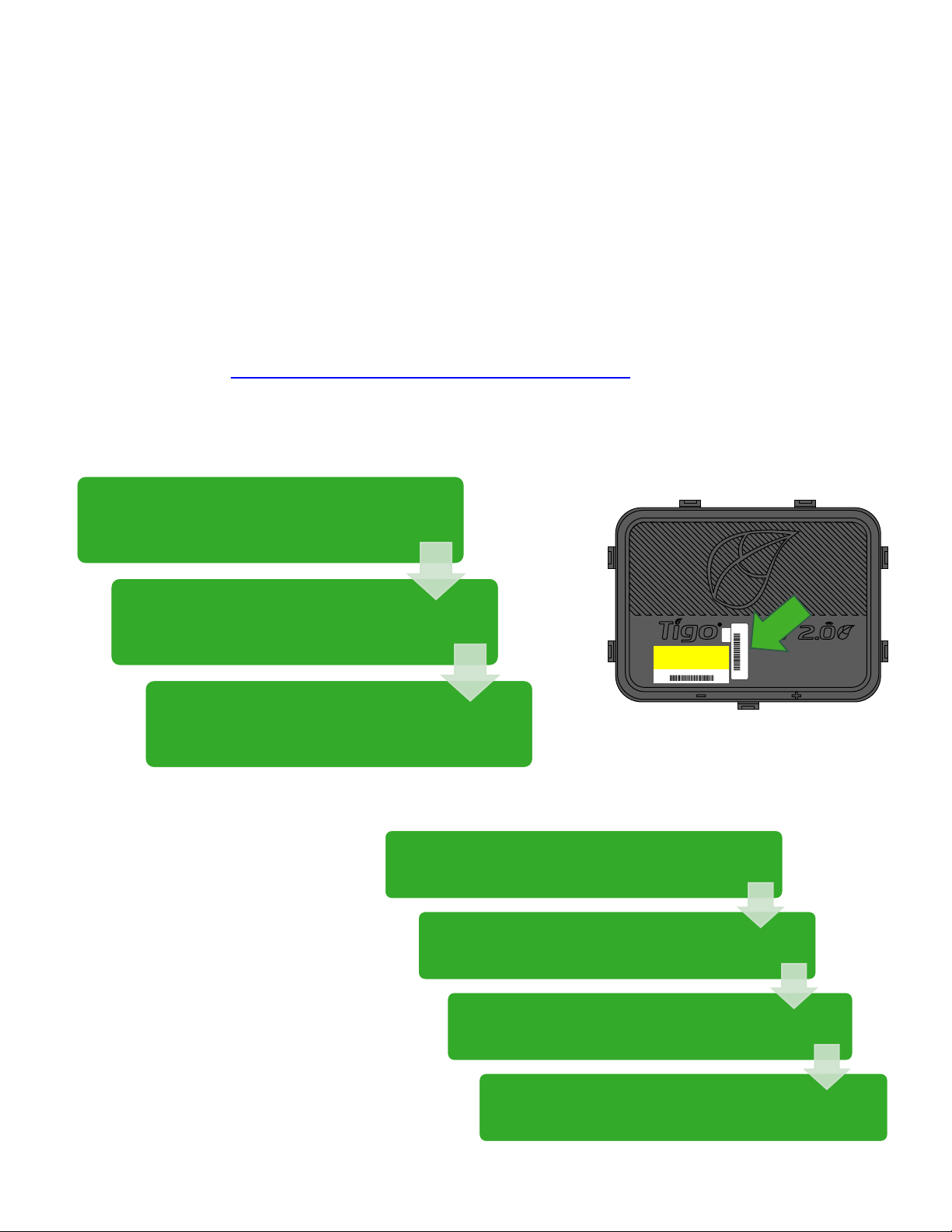
CONFIGURATION, REGISTRATION,
& COMMISSIONING
• Residential systems can perform configuration,
registration, and commissioning via the Tigo SMART App.
• Non-residential systems should perform site configuration
online at https://smart.tigoenergy.com.
Recommended procedure:
Enter site layout online
Type or scan TS4 barcodes
into online layout
Use Tigo SMART app to run
Discovery while on site
OR
Enter site layout online
Type or scan TS4 barcodes
into Excel .csv template*
Upload Excel .csv
template to layout
TS4 - O
4-1234T
4-1234T
Use Tigo SMART app to run
Discovery while on site
* Download the pre-formatted .csv template from the Layout step of the site builder
24
Page 25
TIGO SMART APP
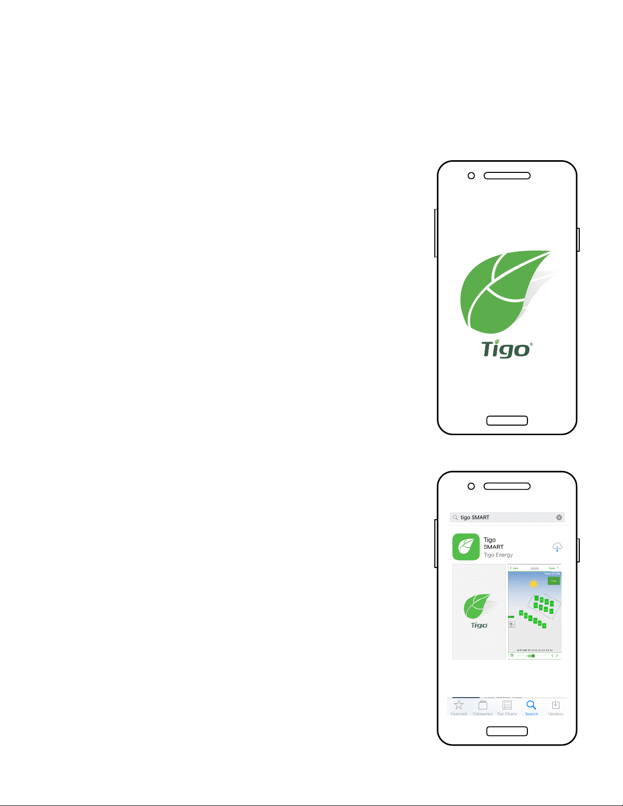
Commissioning a new system using the Tigo App 3.0
Use the Tigo SMART app to:
• Create a system
• Input owner info
• Enter inverter & module types
• Congure layout and scan barcodes
• Congure network
• Commission Tigo hardware
• Monitor production
Install ‘Tigo SMART’ from the App Store or
Google Play
25
Page 26
GETTING STARTED
Requires active mobile data connection
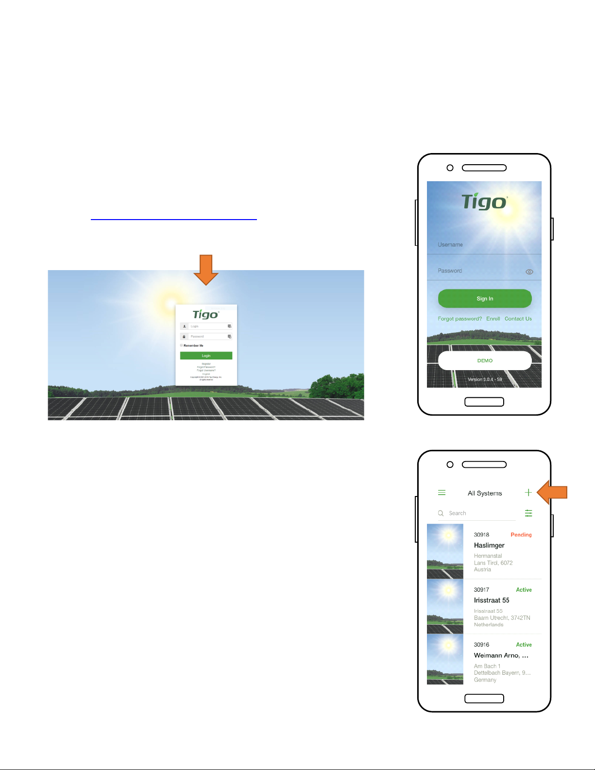
If you do not have an installer account, tap
‘Enroll’ to create a new account. All system
data can also be accessed and edited
here: smart.tigoenergy.com
To proceed with a new installation, tap ‘+’
at the top right of the display
To service or monitor an existing system that
has already been congured, tap on that
system in your list
26
Page 27
SELECT EQUIPMENT
Requires active mobile data connection
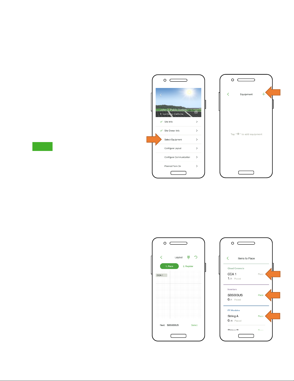
• Go to ‘Select Equipment’
• Tap ‘+’ at the top right of the
display to add equipment
• Choose the inverter model,
the number of MPPTs, and the
associated CCA
• Select the manufacturer and
model of the PV modules
• Note: If using an inverter or
module not in the list, click the
‘+’ sign at the top right corner
• Place the CCA by tapping on
a position on the Layout grid
• Tap ‘Place’ next to an
equipment type to place it on
the grid
• Repeat for all CCAs and
inverters
27
Page 28
CONFIGURE MODULE LAYOUT
Requires active mobile data connection
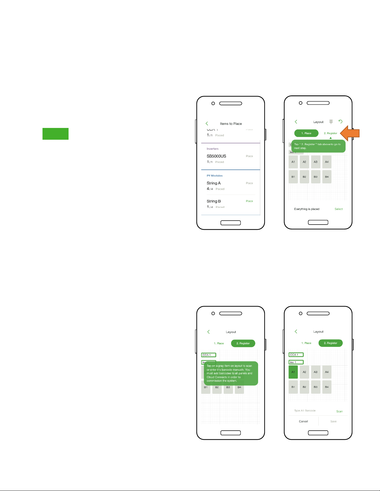
• Place modules in the Layout
grid according to their
physical placement on site
• Note: Matching the physical
map of the system is optional
but improves its appearance
in the monitoring portal and
makes maintenance easier
• Tap and drag to change the
position of a placed item
• Tap ‘Register’ to begin
entering the TS4 barcodes
• Place the CCA by tapping on
a position on the Layout grid
• Tap ‘Place’ next to an
equipment type to place it on
the grid
• Repeat for all CCAs and
inverters
28
Page 29
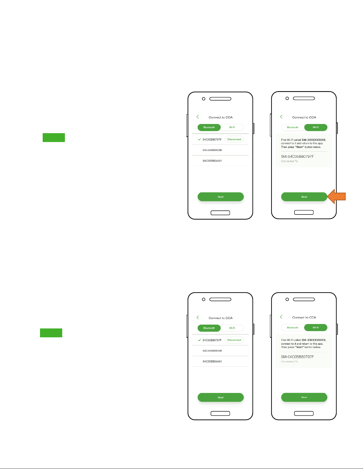
CONNECT CCA TO SMARTPHONE
No mobile data connection required
• To connect the Smartphone to
the CCA via Bluetooth, tap the
serial number of the CCA you
wish to connect with
• Note: Use the Tigo Smart App to
pair with the CCA, instead of the
phone’s Bluetooth pairing screen
• Once connected to the CCA,
tap ‘Next’ to continue
• To connect the smartphone to
the CCA via Wi-Fi, choose the
CCA’s Wi-Fi connection in the
phone’s settings
• Note: Using the Wi-Fi connection
disconnects the smartphone
from the local Wi-Fi
• Once connected to the CCA,
tap ‘Next’ to continue
29
Page 30
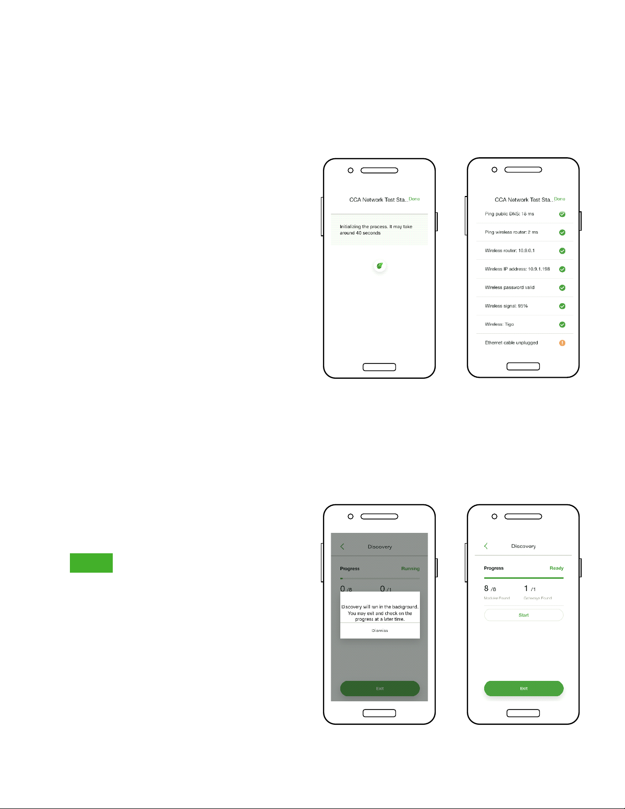
CONFIGURE NETWORK SETTINGS –
CONNECT CCA TO INTERNET
Requires smartphone – CCA connection
• The Network Test checks the
Internet connection of the
CCA
• The test performs a series of
checks that can be used for
troubleshooting the network
connection
• Tap ‘Done’ to continue
COMMISSION THE TS4 UNITS –
RUN DISCOVERY
Requires smartphone – CCA connection
• Tap ‘Next’ in the ‘CCA
Network Settings’ to go to
‘Discovery’
• Note: Before starting
Discovery, all site equipment
and TS4 barcodes should be
input into the app. Begin the
process no later than an hour
before sunset.
• Tap ‘Start’ to run Discovery
• When Discovery is complete,
system production data can be
viewed online and in the app
30
Page 31
STRING DESIGN WITH TS4
TS4-M: MONITORING:
Standard rules for string length and design.
Requires CCA and TAP for monitoring.
Diodes
Monitoring
TS4-S: SAFETY:
Standard rules for string length and design.
Requires CCA and TAP for monitoring and rapid shutdown.
Diodes
Monitoring Safety
TS4-O: OPTIMIZATION:
Standard rules for string length
Flexible design (mixed orientations, unequal length strings in parallel)
Tolerant of shade and mismatch
Diodes
Monitoring
Safety
Optimization
TS4-L: LONG STRINGS:
Increased maximum string length, no derating for cold temperature
Flexible design (mixed orientations, unequal length strings in parallel)
Tolerant of shade and mismatch
Diodes
Monitoring
Safety
Optimization
Long Strings
Click here for TS4-L string sizing rules
31
Page 32

Appendix
Product Specications, Rapid Shutdown,
String Sizing with TS4-L
Page 33
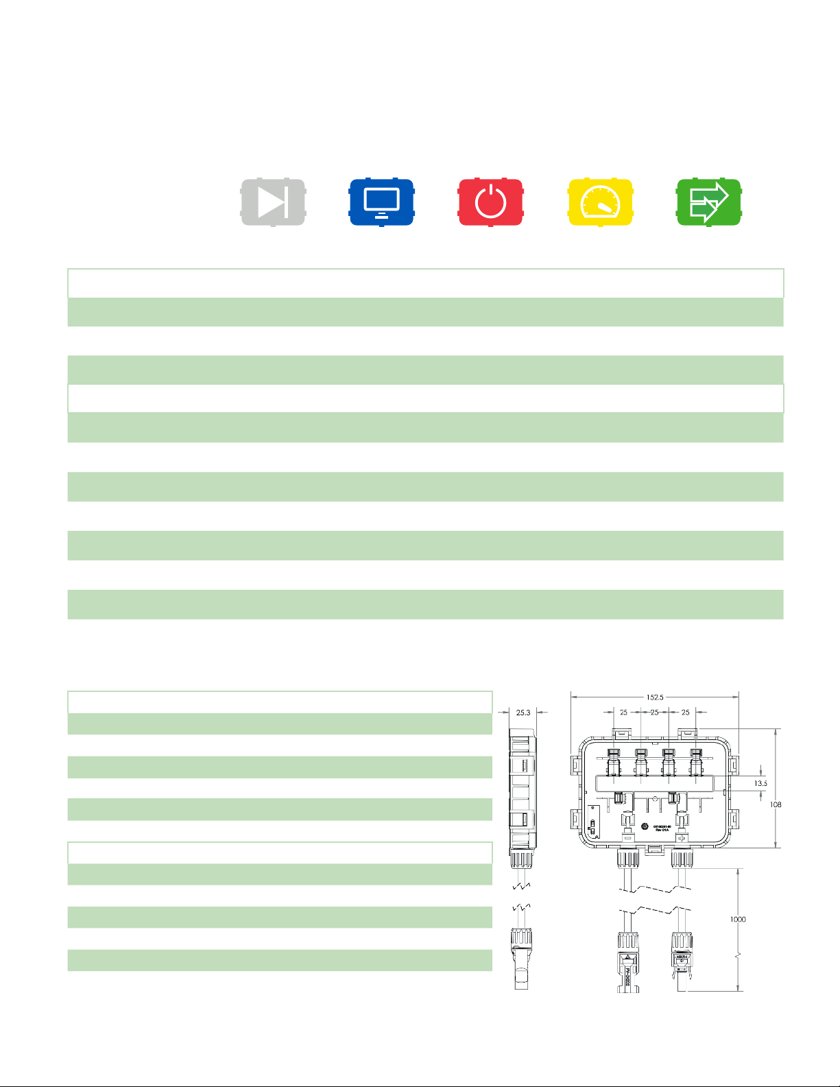
TECHNICAL SPECIFICATIONS –
SMART MODULE WITH TS4-B
Electrical Ratings
DIODES
TS4-D
MONITORING
TS4-M
SAFETY
TS4-S
OPTIMIZATION
TS4-O
LONG STRINGS
TS4-L
Input
Rated DC Input Power - 475W 475W 475W 475W
Input Voltage - 16 - 90V 16 - 90V 16 - 90V 16 - 90V
Max Continuous
Input Current (I
MAX
)
12.5A 12A 12A 12A 12A
Output
Output Power Range 0 – P
Output Voltage Range
Communication Type N/A Wireless Wireless Wireless Wireless
Rapid Shutdown UL Listed
(NEC 2014 & 2017 690.12)
Impedance Matching No No No Yes Yes
Output Voltage Limit No No No No Yes
Maximum System Voltage 1500V 1500V 1500V 1500V 1500V
1
Output voltage limit of TS4-L is factory-set.
2
Cloud Connect Advanced (CCA) and TAP/Gateway required for rapid shutdown compliance with TS4-S, TS4-O, & TS4-L. TS4-F requires
RSS Transmitter.
1
2
MAX
0 – V
OC
Need additional RS
device
0 - 475W 0 - 475W 0 - 475W 0 - 475W
0 – V
OC
Need additional RS
device
0 – V
OC
Yes Yes Yes
0 – V
OC
0 – V
MAX
Mechanical
Operating Temperature Range -40°C to +85°C (-40°F to +185°F), RH < 85%
Storage Temperature Range -40°C to +85°C (-40°F to +185°F), RH < 60%
Cooling Method) Natural Convection
Dimensions (with cover) 152.5mm x 108mm x 25.3mm
Weight 270g (base), 180g to 240g (cover)
Outdoor Rating IP67/IP68, NEMA 3R
Cabling
Type H1Z2Z2-K
Output Cable Length 1.2m (standard)
Rating Options
Cable Cross-Section 6.3 ± 0.3mm
Connectors MC4 (standard), MC4 comparable, EVO2
UV Resistance 500hr with UV light between 300-400nm @65°C
3
1 All TS4 covers are 1500V compatible. Specify max system voltage when ordering modules with TS4 bases for appropriate cables
& connectors.
3
1000V, 1500V
33
Page 34
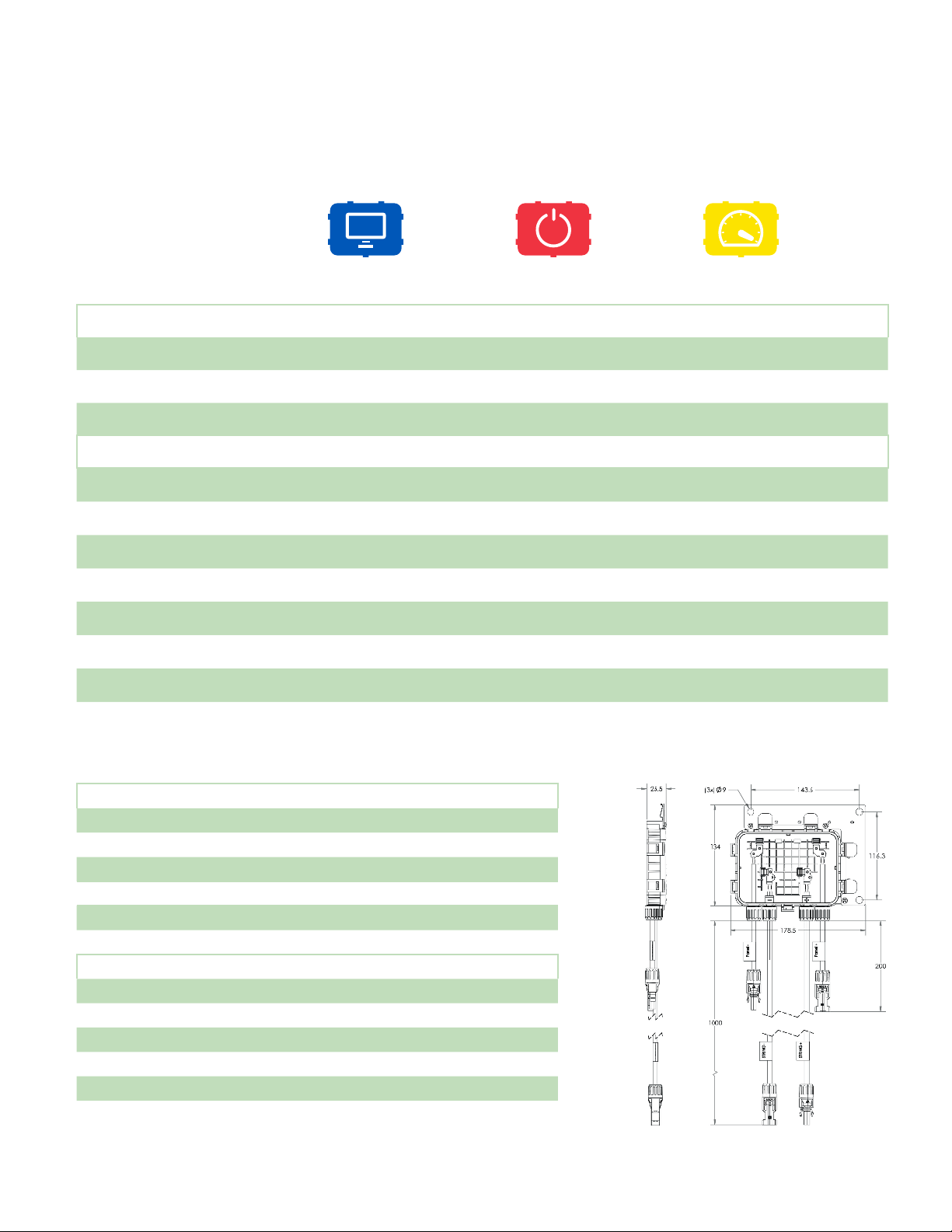
TECHNICAL SPECIFICATIONS – TS4-R
Electrical Ratings
MONITORING
TS4-R-M
SAFETY
TS4-R-S
OPTIMIZATION
TS4-R-O
Input
Rated DC Input Power 475W 475W 475W
Input Voltage 16 - 90V 16 - 90V 16 - 90V
Max Continuous
Input Current (I
MAX
)
12A 12A 12A
Output
Output Power Range 0 - 475W 0 - 475W 0 - 475W
Output Voltage Range 0 – V
Communication Type Wireless Wireless Wireless
Rapid Shutdown UL Listed
(NEC 2014 & 2017 690.12)
Impedance Matching No No Yes
Output Voltage Limit No No No
Maximum System Voltage 1500V 1500V 1500V
1
Cloud Connect Advanced (CCA) and TAP/Gateway required for rapid shutdown compliance with TS4-R-S & TS4-R-O.
1
OC
Need additional
RS device
0 – V
OC
Yes Yes
0 – V
OC
Mechanical
Operating Temperature Range -40°C to +85°C (-40°F to +185°F), RH < 85%
Storage Temperature Range -40°C to +85°C (-40°F to +185°F), RH < 60%
Cooling Method) Natural Convection
Dimensions (with cover) 178.5mm x 134mm x 25.5mm
Weight (base and cover) 610g (M or S cover), 670g (O cover)
Outdoor Rating IP67/IP68, NEMA 3R
Cabling
Type H1Z2Z2-K
Output Cable Length 1m (standard)
Rating Options
Cable Cross-Section 6.3 ± 0.3mm
Connectors MC4, MC4 comparable, EVO2
UV Resistance 500hr with UV light between 300-400nm @65°C
3
1000V, 1500V
34
Page 35
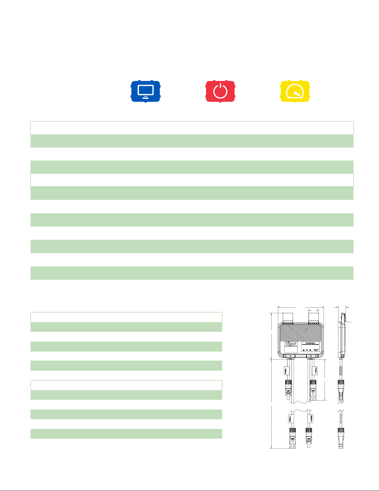
TECHNICAL SPECIFICATIONS – TS4-A
Electrical Ratings
MONITORING
TS4-A-M
SAFETY
TS4-A-S
OPTIMIZATION
TS4-A-O
Input
Rated DC Input Power 500W 500W 500W
Input Voltage 16 - 90V 16 - 90V 16 - 90V
Max Continuous
Input Current (I
MAX
)
15A 15A 12A
Output
Output Power Range 0 - 500W 0 - 500W 0 - 500W
Output Voltage Range 0 – V
OC
Communication Type Wireless Wireless Wireless
Rapid Shutdown UL Listed
(NEC 2014 & 2017 690.12)
1
Need additional
RS device
Impedance Matching No No Yes
Output Voltage Limit No No No
Maximum System Voltage 1500V 1500V 1500V
1
Cloud Connect Advanced (CCA) and TAP/Gateway required for rapid shutdown compliance with TS4-A-S & TS4-A-O.
0 – V
OC
0 – V
Yes Yes
OC
Mechanical
Operating Temperature Range -40°C to +85°C (-40°F to +185°F), RH < 85%
Storage Temperature Range -40°C to +85°C (-40°F to +185°F), RH < 60%
Cooling Method) Natural Convection
Dimensions 138.4mm x 139.7mm x 22.9mm
Weight 490g
Outdoor Rating IP68
Cabling
Type H1Z2Z2-K
Output Cable Length 1.2m
Rating Options
Cable Cross-Section 6.3 ± 0.3mm
Connectors MC4 (standard), MC4 comparable, EVO2
UV Resistance 500hr with UV light between 300-400nm @65°C
3
1000V, 1500V
1200
139.7
138.4
30
120
±10
22.9
8
±10
35
Page 36
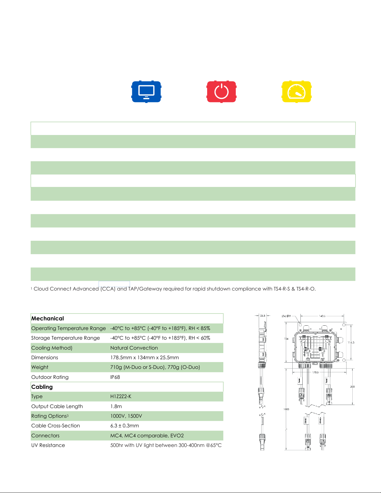
TECHNICAL SPECIFICATIONS – TS4-R-DUO
Electrical Ratings
MONITORING
TS4-R-M-Duo
SAFETY
TS4-R-S-Duo
OPTIMIZATION
TS4-R-O-Duo
Input
Rated DC Input Power 700W 700W 700W
Input Voltage 16 - 90V 16 - 90V 16 - 90V
Max Continuous
Input Current (I
MAX
)
12A 12A 12A
Output
Output Power Range 0 - 700W 0 - 700W 0 - 700W
Output Voltage Range 0 – V
Communication Type Wireless Wireless Wireless
Rapid Shutdown UL Listed
(NEC 2014 & 2017 690.12)
Impedance Matching No No Yes
Output Voltage Limit No No No
Maximum System Voltage 1500V 1500V 1500V
1
Cloud Connect Advanced (CCA) and TAP/Gateway required for rapid shutdown compliance with TS4-R-S & TS4-R-O.
1
OC
Need additional
RS device
0 – V
OC
Yes Yes
0 – V
OC
Mechanical
Operating Temperature Range -40°C to +85°C (-40°F to +185°F), RH < 85%
Storage Temperature Range -40°C to +85°C (-40°F to +185°F), RH < 60%
Cooling Method) Natural Convection
Dimensions 178.5mm x 134mm x 25.5mm
Weight 710g (M-Duo or S-Duo), 770g (O-Duo)
Outdoor Rating IP68
Cabling
Type H1Z2Z2-K
Output Cable Length 1.8m
Rating Options
Cable Cross-Section 6.3 ± 0.3mm
Connectors MC4, MC4 comparable, EVO2
UV Resistance 500hr with UV light between 300-400nm @65°C
3
1000V, 1500V
36
Page 37
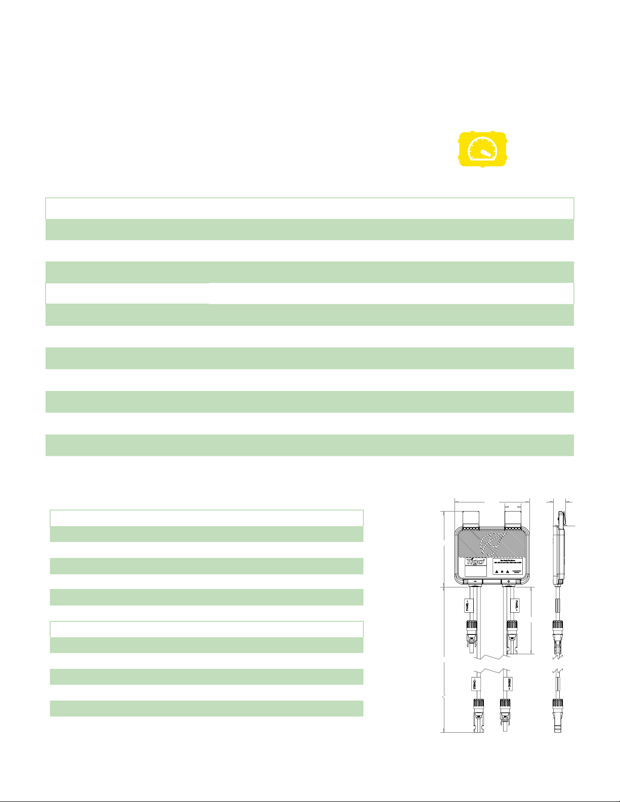
TECHNICAL SPECIFICATIONS – TS4-A-O-DUO
Electrical Ratings
OPTIMIZATION
TS4-A-O-Duo
Input
Rated DC Input Power 700W
Input Voltage 16 - 90V
Max Continuous
Input Current (I
MAX
)
12A
Output
Output Power Range 0 - 700W
Output Voltage Range 0 – V
Communication Type Wireless
Rapid Shutdown UL Listed
1
(NEC 2014 & 2017 690.12)
Impedance Matching Yes
Output Voltage Limit No
Maximum System Voltage 1500V
1
Cloud Connect Advanced (CCA) and TAP/Gateway required for rapid shutdown activation with and TS4-A-O-Duo.
OC
Yes
Mechanical
Operating Temperature Range -40°C to +85°C (-40°F to +185°F), RH < 85%
Storage Temperature Range -40°C to +85°C (-40°F to +185°F), RH < 60%
Cooling Method) Natural Convection
Dimensions 138.4mm x 139.7mm x 22.9mm
Weight 560g
Outdoor Rating IP68
Cabling
Type H1Z2Z2-K
Output Cable Length 1.8m
Rating Options
Cable Cross-Section 6.3 ± 0.3mm
Connectors MC4 (standard), MC4 comparable, EVO2
UV Resistance 500hr with UV light between 300-400nm @65°C
3
1000V, 1500V
1800
139.7
138.4
30
120
±10
22.9
8
±10
37
Page 38
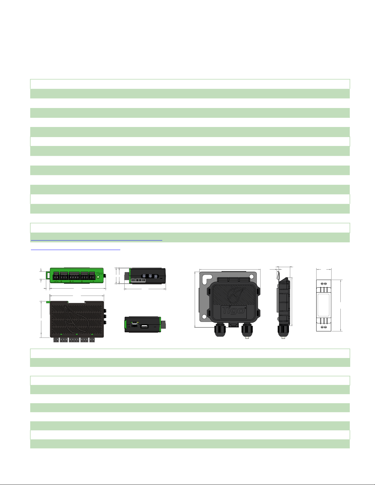
TECHNICAL SPECIFICATIONS –
CCA & TAP
Electrical
CCA
Input Voltage 10VDC- 25V
Power Consumption 3W - 7W
Power Supply 138.4mm x 139.7mm x 22.9mm
Input Voltage 100VAC- 240V
Mechanical
DIN rail mountable enclosure
Dimensions (CCA only) 31mm x 115.51mm x 71.54mm
Weight (CCA only) 126g
Operating Temperature Range -20°C to +70°C (-4°F to +158°F)
Cooling Natural Convection
Capacity
Mesh Conguration Each CCA supports up to 900 TS4 units and up to 7 TAPs
Legacy Conguration Each CCA supports up to 360 TS4 units and up to 7 TAPs
User Interface
Mobile App: Tigo SMART App for Android and iOS
Multi-function LED status indicator
AUX RS485-1 RS485-2GATEWAY POWER
14.96
B A B A B A
7.02 108.87
105.10
70.70
31 30
4 - 103A4543R
Ethernet
Cellular
1 2
80.33
USB
Wi-Fi
115.5
DC
AC
126.2
access point
100.7
Power Supply
(Optional)
+
LL
TAPCCA
3.7
17.5
-
90
NN
All dimensions i n mm.
Electrical
TAP
Input Voltage 24V
DC
Mechanical
Dimensions 126.2mm x 130.0mm x 26.8mm (with bracket)
Weight 227g
Operating Temperature Range -20°C to +85°C (-4°F to 185°F)
Environmental Rating IP68, Type 4R
Cooling Natural Convection
Capacity
Mesh Conguration 300 TS4 units up to 115ft (35m) away
Legacy Conguration 120 TS4 units up to 50ft (15m) away
38
Page 39
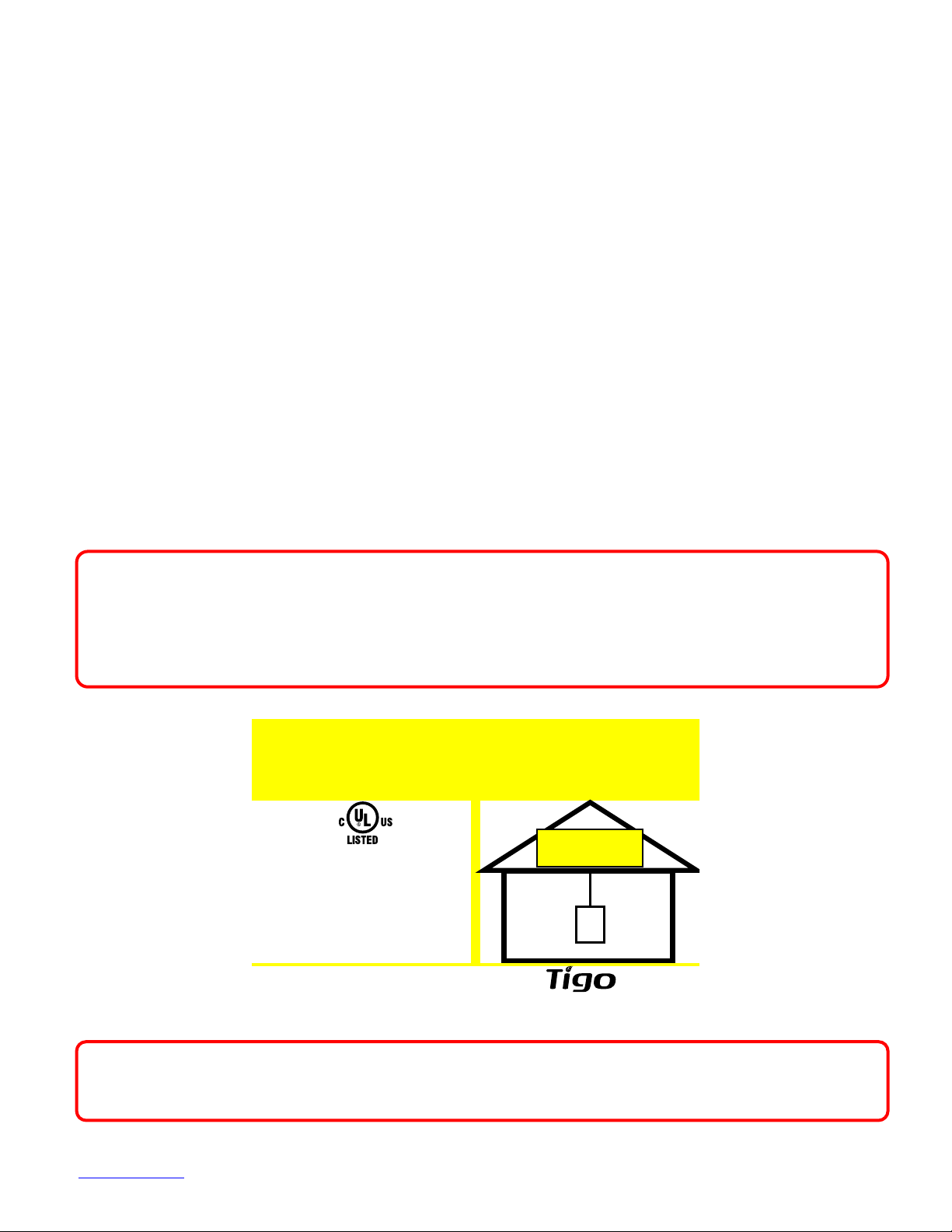
TESTING RAPID SHUTDOWN
TURN RAPID SHUTDOWN
SWITCH TO THE "OFF"
POSITION TO SHUT
DOWN
PV SYSTEM AND REDUCE
SHOCK HAZARD IN
ARRAY
SOLAR ELECTRIC
PV PANELS
TS4-L, TS4-O, and TS4-S (includes TS4-R and TS4-A add-on versions)
with Cloud Connect Advanced and TAP are a solution to meet the
NEC 2014 & 2017 690.12 Rapid Shutdown requirements.
TS4 units with the safety feature automatically enter rapid shutdown
mode when the CCA is switched off and resume energy production
when power is restored to the CCA.
Wait 30 seconds after rapid shutdown activation before disconnecting
DC cables or turning off DC disconnect.
Test your rapid shutdown system by switching off the AC power to the CCA.
TS4 units with the safety feature will reduce their output to 0V when the CCA
is powered off.
SOLAR PV SYSTEM EQUIPPED
WITH RAPID SHUTDOWN
Photovoltaic Rapid
Shutdown System, QIJS
E469960
WHEN USED WITH
Place safety labels in proper location
TS4
The CCA power supply MUST be on the same AC branch circuit as the
inverter to meet rapid shutdown requirements.
Click here for more info about Rapid Shutdown
39
Page 40
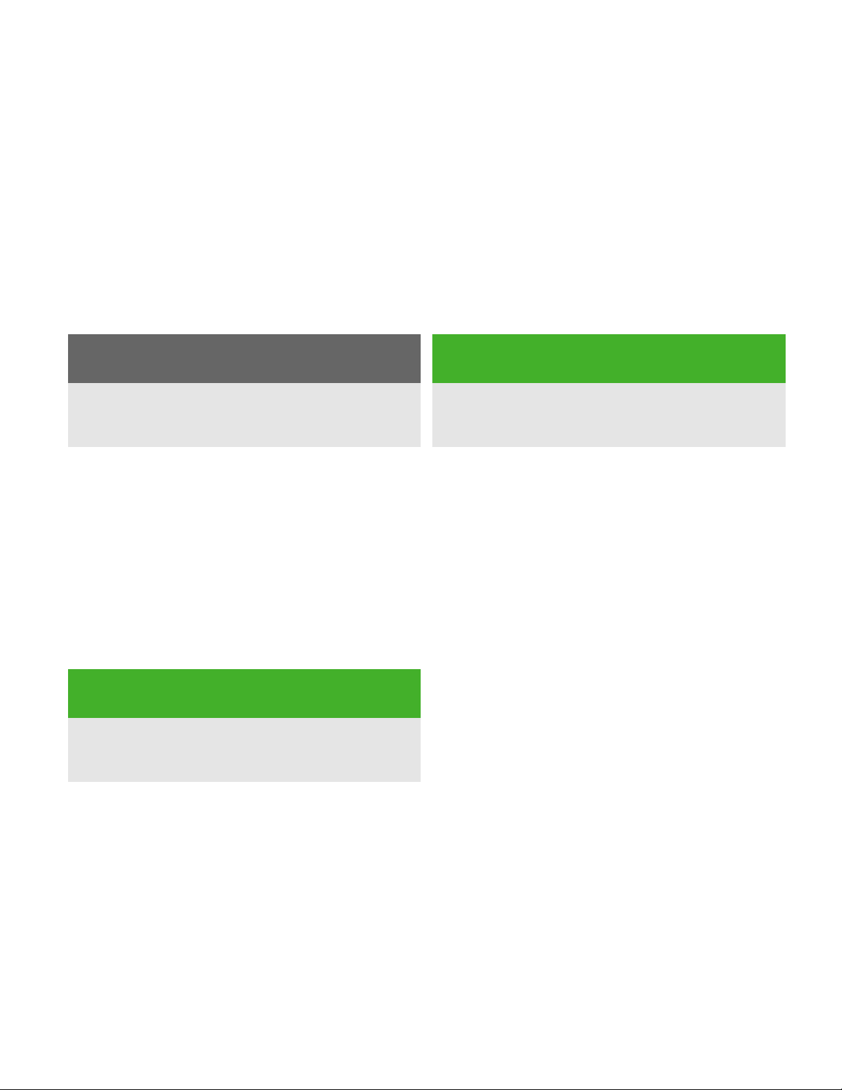
STRING SIZING WITH TS4-L
TS4-L has a state of the art technology designed to reduce balance of system
costs by allowing longer strings. This can reduce the number of strings by up
to 30%, which directly correlates to a 30% reduction in combiner boxes, wiring,
fuses, and hardware overhead costs, as well as reducing the labor
requirement for installation.
By code:
Traditional String Design:
Max.
string
V
OC
Example Calculation (based on a 260W module):
Max. VOCfor code: 600V
V
range: 190-510V
MPP
Module VOC: 38.2V
Module VMP: 30.6V
Temp. Corrected VOC: 38.2 * 1.25 = 47.75V
Max. string: 600V ÷ 47.75V = 12 modules
÷
Temp
corrected
V
OC
# of
=
modules
per string
By inverter:
Verify maximum string length
according to inverter parameters
Inverter MPP
Voltage Max.
÷
Module
V
MP
=
# of
modules
per string
TS4-L String Design:
Max.
string
V
OC
Max. VOCfor code: 600V
Inverter V
Reduced VOC: 35V
Module VMP: 30.6V
Temp. Corrected VOC: 35V * 1 = 35V
Max. string: 600V ÷ 35V = 17 modules
range: 190-510V
MPP
÷
Reduced
V
OC
# of
=
modules
per string
Verify string VMPlimits by dividing inverter max MPP voltage range by the Smart Module's VMP.
From the example above: 510V ÷ 30.6V = 16 modules per string by inverter
In case of discrepancy between the code requirement and the inverter voltage
requirement pick the lower number of the two. Therefore, this example results in a maximum
of 16 panels per string, a 33% increase in string power, with a corresponding reduction in
electrical BOS costs.
40
Page 41
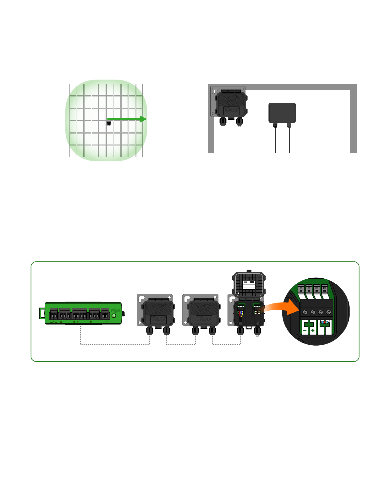
TAP PLACEMENT - LEGACY(PRE-MESH
PWR DATA
B A
access point
accesspoint
50ft (15m)
)
Place TAP near center of array or each
sub-array.
AUX RS485-1 RS485-2GATEWAY POWER
B A B A B A
access point access point
TAP attaches to module frame using
built-in bracket. Mounting holes are also
available in case of frameless modules.
OR
Quickconnectors:
Connectorblocks:
presswireinto terminal
usescrewterminals
Removeresistor to connect
anotherAccess Point in series.
IN OUT
-
A
B
+
PWR PWRDATA DATA
B BA A
Connect multiple TAP units in series and leave terminating resistor in final TAP only.
Use 4-conductor RS485 (18-22 AWG) cable between TAP and CCA.
Legacy conguration (same as Gateway):
• 120 TS4 units per TAP
• 360 TS4 units per CCA
• 7 TAPs per CCA
• 50ft (15m) radius with line of sight between TAP & all TS4 units
41
Page 42

INSTALLATION COMPLETE
For more details on designing and
installing solutions powered by Tigo,
please visit:
Tigo Academy
Resource Center
Or contact us at:
For sales info:
[email protected] or 1.408.402.0802
For technical information:
http://support.tigoenergy.com
For product info:
Visit www.tigoenergy.com/products
For additional info and product selection
assistance, use Tigo’s online design tool at
www.tigoenergy.com/design
Tigo Energy, Inc. 420 Blossom Hill Rd, Los Gatos, California 95032 USA | www.tigoenergy.com
P: +1.408.402.0802 F:+1.408.358.6279 | [email protected]
 Loading...