

Page 1

Cablecast SX
Setup Guide
c
Tightrope Media Systems
For Cablecast version 5.3.6 Build 221
Printed June 5, 2015
Page 2

1 Cablecast SX Setup
1.1 Prerequisites
1.2 Overview of Setup
Thank you for purchasing a Cablecast SX video server from Tightrope Media
Systems! This guide will walk you through setting up your new server.
Before beginning the installation, please make sure that you have the following
resources available:
• An ethernet network connection
• A keyboard, mouse, and a VGA monitor
•
Your existing A/V infrastructure (At least one video monitor, if you’re just
testing)
There are three parts to setting up your SX server: Physical Setup, Software Setup,
and Testing.
Physical Setup :
Software Setup :
Testing :
Starting in chapter 2, you’ll learn about the physical connections on the Cablecast
SX server, and how to tie it into your existing infrastructure.
Next, in chapter 3, you be taken through the steps necessary to configure the
Cablecast SX server software.
Finally, in chapter 4, you’ll run some simple tests to make sure the Cablecast SX
server is correctly configured and ready to use.
So, without any further delay, let’s get started!
1
Page 3

2 Part I: Physical Setup
In this section, we’ll be going over the physical setup of the Cablecast SX server.
2.1 In the box
Your Cablecast SX server should come with the following items in the box:
AC power cables : Powers the Cablecast SX server.
SX server : The Cablecast SX server itself.
SX breakout cables :
These breakout cables allow you to connect the SX server into your station’s
infrastructure. See figure 2.1 on the following page for an example of SD breakout
cables for the SX-LE, SX-2, and SX-4. figure 2.2 on the next page shows an
example of the HD breakout cables for the SX2-HD. The SXLE-HD does not
require any breakout cables.
The SX-LE and SX-2 come with one set of two breakout cables (one video and
one audio), and the SX-4 comes with two sets of video and audio cables (two
video, two audio). The SX2-HD also has one set of two breakout cables (one
video and one audio) but they carry SDI video and AES/EBU audio.
2
Page 4

FI GU RE 2.1:
SD Breakout Cables.
The Cablecast SX
FI GU RE 2.2:
HD Breakout Cables.
The Cablecast SX
2 Part I: Physical Setup 3
Page 5

2.2 Physical Connections
2.2.1 System Connections
2.2.2 AV Connections
On the back of your Cablecast SX server, you’ll see several ports. Please refer to
the appropriate section for your server, as the ports are somewhat different.
All of the Cablecast SX servers share some basic system connections:
1. Connect a keyboard and mouse. One PS/2 port is provided, and can be used
for either a keyboard or mouse. USB keyboards and mice are suggested if
possible.
2.
Connect a monitor. The monitor is required for server setup, and we recommend that it remain connected. The Cablecast SXLE-HD has a single VGA
port, whereas the other server have a DisplayPort and DVI-I port. A DVI to
VGA adapter is included.
3.
Connect the Cablecast SX server to the network via one of the ethernet
network jacks.
4.
Connect the Cablecast SX server’s power supply to an AC power source
using the provided AC power cables.
Next, you will connect the Cablecast SX server to your video infrastructure.
SX-LE and SX-2
SX-4
The SX breakout cables are “keyed” so that they can only fit in the appropriate
port on the back of the SX server. Do not force the SX breakout cables into the
port!
The video and audio connections on the Cablecast SX-LE and Cablecast SX-2 are
identical.
1. Connect the video breakout cable to the VIDEO port.
2. Connect the audio breakout cable to the AUDIO port.
See section 2.2.4 for an explanation of the connectors on each breakout cable.
1. Connect a video breakout cable to the VIDEO port labeled AV I/O 1.
2. Connect a video breakout cable to the VIDEO port labeled AV I/O 2.
3. Connect a audio breakout cable to the AUDIO port labeled AV I/O 1.
4. Connect a audio breakout cable to the AUDIO port labeled AV I/O 2.
See section 2.2.4 for an explanation of the connectors on each breakout cable.
2 Part I: Physical Setup 4
Page 6

1
7
8
9
AC power
1
PS2
2
USB 2.0
3
RS-232
4
Ethernet
5
2
4
3
FI GU RE 2 .3 : The Cablecast SX-LE
5
6
USB 3.0
6
DVI-I and DisplayPort
7
AUDIO
8
VIDEO
9
8
7
1
AC power
1
PS2
2
USB 2.0
3
RS-232
4
Ethernet
5
2 Part I: Physical Setup 5
2
4
3
FI GU RE 2 .4 : The Cablecast SX-2
5
6
USB 3.0
6
DVI-I and DisplayPort
7
VIDEO
8
AUDIO
9
9
Page 7

AC power
1
PS2
2
USB 2.0
3
RS-232
4
Ethernet
5
USB 3.0
6
8
7
1
2
4
3
FI GU RE 2 .5 : The Cablecast SX-4
5
6
DVI-I and DisplayPort
7
VIDEO 1
8
AUDIO 1
9
VIDEO 2
10
AUDIO 2
11
9
10
11
SXLE-HD
The Cablecast SXLE-HD does not require any breakout cables.
1.
Connect a cable from
2.
Connect a cable from an output of your SD/HD-SDI routing switcher to
3. Connect house tri-level or analog blackburst to Ref In.
SX2-HD
1.
Connect the video breakout cable to the large 8-coaxial pin connector. These
outputs also have embedded audio.
2.
Connect the audio breakout cable to the keyed 26-pin connector labeledAif
you plan to use AES/EBU audio.
See section 2.2.5 for an explanation of the connectors on each breakout cable.
2.2.3 Final Connections
Next, connect the SX breakout cables to your existing AV infrastructure as needed.
Each individual cable on the SX breakout “bundle” is labeled as described in
2 Part I: Physical Setup 6
Out 1
to an input on your SD/HD-SDI routing switcher.
In 1
.
Page 8

AC power
1
PS2
2
USB 2.0
3
RS-232
4
Ethernet
5
1
234
7
FI GU RE 2 .6 : The Cablecast SXLE-HD
5
6
6
7
8
9
10
USB 3.0
VGA
OUT 1
IN 1
REF IN
8
9
10
AC power
1
PS2
2
USB 2.0
3
RS-232
4
Ethernet
5
8
7
1
2
4
3
FI GU RE 2 .7 : The Cablecast SX2-HD
5
6
USB 3.0
6
DVI-I and DisplayPort
7
AUDIO
8
VIDEO
9
9
2 Part I: Physical Setup 7
Page 9
2.2.4 SD SX AV Connections
CVBS In : Encoder composite video input
Y In : Not used
U/Y In : Not used
V/C In : Not used
AES In : Encoder AES/EBU input
SDI In : Encoder SDI input
Ref In : Genlock input
Y/CVBS Out A : Playback channel 1 composite output
U/Y Out : Not used
V/C Out : Not used
AES Out 1/2 : Playback channel 1 AES/EBU output
section 2.2.4 for the SX-LE, SX-2, and SX-4. See section 2.2.5 for the SX2-HD
breakout cables.
Once your Cablecast SX server is connected, power on the server by pressing the
power button on the front of the computer.
Each SD SX video breakout cable has the following connections:
SDI Out A : Playback channel 1 SDI output
CVBS Out B : Playback channel 2 composite output
AES Out 3/4 : Playback channel 2 AES/EBU output
SDI Out B : Playback channel 2 SDI output
Each SD SX audio breakout cable has the following connections:
In 1 : Encoder audio input (Left)
In 2 : Encoder audio input (Right)
Out 1 : Playback channel 1 audio output (Left)
Out 2 : Playback channel 1 audio output (Right)
Out 3 : Playback channel 2 audio output (Left)
Out 4 : Playback channel 2 audio output (Right)
The audio connections on the Cablecast SX servers are balanced. If your AV
infrastructure requires unbalanced audio, you will need to use proper converting
equipment to convert to unbalanced.
2 Part I: Physical Setup 8
Page 10

2.2.5 HD SX AV Connections
SDI In A : Encoder SDI video Input
SDI In B/Key : Not used
Analog Ref In : Reference signal input (tri-level or blackburst)
SDI Out A : Playback channel 1 SDI output
SDI Out B : Not used
SDI Out C/Key : Playback channel 2 SDI output
SDI Out D/Key : Not used
Analog Ref Loop Out : Reference signal loop output
AES In 1/2 : Encoder AES/EBU input
AES In 3/4 : Not used
AES In 5/6 : Not used
AES In 7/8 : Not used
AES Out 1/2 : Playback channel 1 AES/EBU output
AES Out 3/4 : Not used
The SX2-HD video breakout cable has the following connections:
The SX2-HD audio breakout cable has the following connections:
AES Out 5/6 : Playback channel 2 AES/EBU output
AES Out 7/8 : Not used
AES Out 9/10 : Not used
AES Out 11/12 : Not used
AES Out 13/14 : Not used
AES Out 15/16 : Not used
2 Part I: Physical Setup 9
Page 11
3 Part II: Software Setup
Now that you’ve connected your Cablecast SX server to your AV infrastructure, it’s
time to configure the Cablecast software. There are four steps involved in software
configuration:
1. Control Module Hosts
2. Control Module Sets
3. Devices
4. Cablecast SX server Settings
In order to begin the software setup, you must log into the Cablecast Web Interface
via FrontDoor. From the desktop of the Cablecast SX server, open up a web browser,
and navigate to “http://localhost/FrontDoor”
If you are connecting your Cablecast SX server to a Cablecast Pro server, you’ll
need to log into the Cablecast Web Interface that resides on the Cablecast Pro
server. In this configuration, the Cablecast SX server is being controlled by
the Cablecast Pro server, so all web-based configuration will take place on the
Cablecast Pro server.
By default, FrontDoor ships with an Admin user account with the following
credentials:
1
Username: Admin
Password: trms
For more information about user accounts and logging into FrontDoor,
see the FrontDoor User Manual.
Once you have logged into Cablecast, you will see the Cablecast Main Menu page,
as shown in figure 3.1 on the following page.
1
You can perform this configuration over the network as well. Just replace “
address of the Cablecast SX server.
localhost
” with the IP
10
Page 12
FI GU RE 3 .1 :
the Cablecast Web Interface.
The Main Menu of
3.1 Creating Control Module Hosts
The first step is to inform the Cablecast software of the new Cablecast SX server.
We’ll accomplish this by creating a “Host” for the Control Modules2.
From the Main Menu, navigate to
System Settings : Control Module Hosts
.
A warning screen will appear when you first enter the Control Module Hosts
page, which is designed to prevent accidental modification of critical system
settings. In this case, we want to modify the system settings, so it is safe to
dismiss the warning by clicking the “Continue” button.
Depending on your system setup, there are two ways to configure the Control
Module Hosts page:
If you’re running a standalone Cablecast SX server:
There’s a good chance that this Control Module Host already exists. If it does,
please skip this step.
1. Create a single Control Module Host entry (if there isn’t one already)
2. Enter a Name of “localhost”
3. Enter a Host Address of “localhost”
The screen should look something like figure 3.2 on the next page. Click the “
Save
button.
If you’re running a Cablecast SX server that is controlled by a Cablecast Pro
server:
1. Create a new Control Module Host entry
”
3 Part II: Software Setup 11
2. Enter a Name of “Cablecast SX”
2
Cablecast’s Control Modules are in charge of controlling devices, such as video servers, VTRs, DVD
players, Routing switchers, and more.
Page 13
FI GU RE 3 .2 :
Hosts screen in a standalone
configuration.
Control Module
3. In the Host Address field, enter the IP address3of your Cablecast SX server
The screen should look something like figure 3.3. Click the “Save” button.
FI GU RE 3 .3 :
ule Hosts screen in a slave
configuration
Control Mod-
You may have more Control Module Hosts defined, depending on your specific
system setup. For more information about Control Module Hosts, please see the
Cablecast User Manual.
Having informed Cablecast of the new Cablecast SX server, we can continue to the
next step; creating a Control Module Set.
3.2 Creating Control Module Sets
Each “Host” defined in the Control Module Hosts page can be running many
different Control Modules, each controlling different devices. In this next section,
we’ll define a specific “set” of Control Modules that are in charge of controlling the
Cablecast SX server.
3 Part II: Software Setup 12
From the Main Menu, navigate to
Location Settings
, and click on theIOtab.
Another warning screen will appear the first time you select theIOtab. Again,
in this case we want to modify the system settings, so it is safe to dismiss the
warning by clicking the “Continue” button.
Once on the IO tab, select Control Module Sets.
3
You may also enter the DNS name of the Cablecast SX server in place of an IP Address.
Page 14
We will be creating two new Control Module Sets for your Cablecast SX server;
one to control playback, and another to control recording. To create the playback
Control Module Set (CMS, for short):
1. Click the “New” button to create a blank CMS.
2. Give the new CMS a name of “SX Playback”
3.
In the
Control Module
dropdown list, select the “
SXPlayerCM
” that corre-
sponds to the Control Module Host you created in the previous section.
4.
In the
Port/IP/LocalPath
field, enter the path to the content directory on
the Cablecast SX server. This is the directory where your digital files reside.
Typically, “E:\”.
Next, create the recording Control Module Set:
1. Click the “New” button to create a blank CMS.
2. Give the new CMS a name of “SX Encoder”
3.
In the
Control Module
dropdown list, select the “
SXEncoderCM
” that corre-
sponds to the Control Module Host you created in the previous section.
4.
In the
Port/IP/LocalPath
field, enter the path to the content directory on
the Cablecast SX server. This is the directory where your digital files reside.
Typically, “E:\”.
When finished, your Control Module Sets should look something like figure 3.4.
FI GU RE 3 .4 :
screen after configuring a Cablecast
SX server.
A typical CMS
Regardless of which of the Cablecast SX models you purchased, you will need
to create exactly two Control Module Sets per server. You will most likely have
several other Control Module Sets configured for the various other devices being
controlled by Cablecast.
Now that we have created the Control Module Sets for the Cablecast SX server, we
need to define the specific playback and recording devices that are controlled by the
new Control Module Sets.
3 Part II: Software Setup 13
Page 15
3.3 Creating Devices
Each Cablecast SX server has a collection of playback and recording devices.
You can think of these as inputs and outputs. Specifically, the SX-LE, SX-2, and
SX2-HD each have two playback outputs, and one recording input. The SX-4 has
four playback outputs, and two recording inputs. In this section, we’ll configure
Cablecast to control these input and output devices.
3.3.1 Create Playback Devices
Router Address : Enter the input number of your routing switcher
Device Function : “Playback Only”
Device Type : “Digital File”
Device CMS :
Device Address :“0
To begin, from the Main Menu, navigate to
and enter the Devices page.
In the following section, the specified settings must be configured as stated.
There are other settings available on each screen, and these extra settings can be
configured to suit your station’s needs.
1. Click the New button to create the first playback device.
2.
Click in the newly created device (labeled
Device screen.
3. Enter the following information in the device fields:
Name : “SX Playback 1”
Select the “SX Playback” Control Module Set that you created in section 3.2
on page 12.
”. Device addresses are zero-based, so the first playback device’s address
is zero.
Location Settings
New Input
, click on theIOtab,
) to enter the Edit
Device End Action : Select “Stop”
When finished, your screen should like like figure 3.5 on the next page. Click
to return to the device list screen.
If your server has additional outputs, you will now create a second playback device.
1. Click the New button to create the second playback device.
2.
Click in the newly created device (labeled
Device screen.
3. Enter the following information in the device fields:
Name : “SX Playback 2”
Router Address : Enter the input number of your routing switcher
Device Function : “Playback Only”
Device Type : “Digital File”
3 Part II: Software Setup 14
New Input
) to enter the Edit
Save
Page 16
FI GU RE 3 .5 :
playback device.
Setting up the first
Device CMS :
Device Address :“1
Device End Action : Select “Stop”
3.3.2 Create Record Devices
Select the “SX Playback” Control Module Set that you created in section 3.2
on page 12.
”. Device addresses are zero-based, so the second playback device’s address
is one.
When finished, your screen should like like figure 3.6 on the next page. Click
to return to the device list screen.
If you have an SX-4:
Create two more playback devices (SX Playback 3 and
SX Playback 4), following the pattern as described for the SX-LE, SX-2, and
SX2-HD. Playback devices 1 and 2 (with device addresses of 0 and 1) are located
on the
AV I/O 1
port, and playback devices 3 and 4 (device addresses 2 and 3)
are located on the AV I/O 2 port.
Next, we’ll configure the record device(s).
To create the first record device:
1.
Once again, click the “
New
” button on the device list screen to create a new
record device.
2.
Click in the newly created device (labeled
New Input
) to enter the Edit
Device screen.
Save
Name : “SX Record 1”
3 Part II: Software Setup 15
3. Enter the following information in the device fields:
Page 17
FI GU RE 3 .6 :
second playback device.
Setting up the
Device Function : “Record Only”
Device Type : “Digital File”
Device CMS :
Select the “SX Encoder” Control Module Set that you created in section 3.2
on page 12.
Device Address :“0
”. Device addresses are zero-based, so the first record device’s address is
zero.
Device End Action : Select “Stop Record”
Router Output :
Enter the output number of your routing switcher that is connected to this
record
When finished, your screen should like like figure 3.7 on the next page. Click
to return to the device list screen.
If you have an SX-4:
Create one more record device (SX Record 2), following
the pattern as described above. Remember to set the
the second record device to “1”, as the field is zero-based. Additionally, the
first record device will use the breakout cables plugged into the port labeled
I/O 1 on the back of the SX-4 server, and the second record device will use the
cables plugged into AV I/O 2.
Device Address
Save
field of
AV
3 Part II: Software Setup 16
Page 18

FI GU RE 3 .7 :
device.
Setting up the record
3.4 Cablecast SX Server Settings
FI GU RE 3 .8 :
tion utility.
The SX Configura-
The last set of software settings allow you to modify specific playback and record
parameters of the Cablecast SX server. All of these settings are configured via
the
SX Configuration
system tray utility that is installed on the Cablecast SX
3 Part II: Software Setup 17
Page 19
3.4.1 Playback Tab
server, and cannot be configured via the Cablecast Web Interface. To access the SX
Configuration utility, double-click on the icon in the system tray.
The SX Configuration utility looks like a green circle with the letters SX in the
middle (see figure 3.8 on the preceding page).
FI GU RE 3 .9 :
SX-4.
Playback tab for an
Component output :
Audio level :
The
Playback
tab (seen in figure 3.9) allows you to configure two options for each
output:
This option is only available on output 0 (and output 2 on the SX-4) of the SD SX
servers (SX-LE, SX-2, and SX-4), and is not officially supported by Tightrope Media
Systems. When this option is enabled, the composite cable for the output (labeled
Y/CVBS Out A
Disabling this option returns the
is transformed into the “Y” part of the three component cables.
Y/CVBS Out A
cable to carrying composite video.
Allows you to configure the audio level for this output. This setting affects all
content played from this output.
Changing the values of the playback controls will apply your changes in realtime. It may not be a good idea to alter these settings while your SX server is
on-air.
SDI output is always enabled. Video will be played back on both the SDI output
and the Composite outputs, depending on which is selected. Audio will be
played back on all audio outputs.
The component video output is not supported on the Cablecast SX servers. While
you may choose to use it, Tightrope Media Systems will not be able to provide
help or support for this configuration.
On this tab, you’ll also see a status column that reports the current state of the
output. As a file is playing, a progress bar will display how far into the file the
playback has progressed.
3 Part II: Software Setup 18
Page 20
3.4.2 Record Tab
The status column updates approximately once every five seconds, it is not a
real-time status monitor of your video server.
FI GU RE 3 .1 0:
SX-4.
Record tab for an
VBI :
Video Input :
The
Record
tab (seen in figure 3.10) allows you to configure several options for
encoding video on your SX server:
When checked, VBI data (V-chip, closed captioning) will be encoded if available.
The VBI data stream will be automatically saved as a separate file next to the video
file, with a file name of “vbi_<filename>.avi”.
Selects which of the video input cables from the SX Video Breakout bundle will
be used to record video. Choices are
Composite,Component
(not supported),
S-Video, SDI, and Bars.
Audio Input :
Selects which of the audio input cables from the SX Audio Breakout bundle will be
used to record audio. Choices are Analog, Embedded4, AES/EBU, and Tone.
Changing the values of the record controls will apply your changes in real-time.
It may not be a good idea to alter these settings while your SX server is actively
encoding.
The component video input and the AES/EBU audio input are not supported on
the Cablecast SX servers. While you may choose to use them, Tightrope Media
Systems will not be able to provide help or support for these configurations.
3.4.3 System Tab
In the
System
other settings and features of your SX server. The first setting (in the
tab (shown in figure 3.11 on the next page), you can configure various
Resolution
section) allows you to adjust the video resolution that the SX server uses. Choices
include
480i SD,480i Widescreen
, or
576i SD PAL
, HD servers also support
720p
1280x720 and 1080i 1920x1080.
The Resolution setting applies to both playback and recording.
4
available only when SDI is selected as the video input
3 Part II: Software Setup 19
Page 21
FI GU RE 3 .1 1:
dialog box
The Server Options
The second setting (in the
sync to an external genlock source, which should be connected to the
Genlock
section) allows you to define if the server should
Ref In
cable
on the SX Video breakout cables. If this setting is checked, the SX server will
sync to the provided genlock source. If it is unchecked, internal genlock will be
used. The current Genlock Status is shown, if you are using External Genlock the
status should be
Free Running
Locked
. If you are using Internal Genlock, the status should be
. The next setting (in the
Maintenance
section) controls how the
SX server performs maintenance required for the system’s media storage. You can
use the check box to enable or disable the maintenance completely (disabling it is
not recommended). When it is enabled it will perform storage maintenance at the
specified time every day.
Maintenance may interrupt playback or encoding on your server so you should
choose a time that the system is not busy. The default is 3:00AM, but can be
changed to any time that suits your environment.
The final area of the
Server
tab (
Version Information
) lists version numbers for
each component of the SX video server system. If you require support from
Tightrope Media Systems on your SX server, please have these version numbers
handy. Your server will confirm that the correct Matrox drivers are installed and
warn you if there is a mismatch.
3 Part II: Software Setup 20
Page 22
4 Part III: Testing
4.1 Prepare to Test
4.2 Test Playback
Now that you’ve hooked up and configured your Cablecast SX server, it’s time to
run some simple tests to ensure that playback and recording are working as you
expect.
You will need to have a few items available before beginning your testing:
•
At least one SX-compatible video file to play back (see section 5.1 on page 23)
• A video and audio source to test recording
•
An NTSC or SDI video monitor and an audio monitor (if your Cablecast SX
is already connected to your existing AV infrastructure, you may route the
SX outputs to your monitoring equipment via your routing switcher)
To begin, we’ll test audio and video playback. On the Cablecast SX server, perform
the following steps for each of your video outputs.
1. Double-click the SX Configuration utility and select the Playback tab.
2. Click the Play button on an output.
3.
In the
Open File
Open.
4.
After a moment, the file should begin playing on the chosen output. Check
that both audio and video are played back.
5. When finished, click the Stop button for the same output.
6. The file should stop playing.
If your file doesn’t play back:
• Are you monitoring the correct output?
•
Does your file meet the SX playback requirements (outlined in section 5.1
on page 23)?
• Are you connected to the correct cables on the SX breakout bundles?
If everything appears correct, you may need to go back and double check your
software configuration.
dialog box that appears, select your test video file and click
21
Page 23

4.3 Test Recording
Next, we’ll test audio and video recording. On the Cablecast SX server, perform
the following steps for your video input (both inputs, if you have an SX-4).
1. Connect valid video and audio sources to the record input.
2. Double-click the SX Configuration utility and select the Record tab.
3. Click the Record button on an input.
4.
In the
Save As
for your video file and click Save.
5. The Cablecast SX server should begin recording to the file you selected.
6. After recording for about a minute or so, click the Stop button for the input.
7. The Cablecast SX server will stop recording.
8.
Repeat the playback tests (from section 4.2 on the preceding page) with the
newly recorded file to make sure that both audio and video were correctly
recorded.
If your file doesn’t play back and you suspect it wasn’t recorded correctly:
• Are you connected to the correct cables on the SX breakout bundles?
•
Double check your video/audio source. Does it display correctly if
plugged in directly to a monitor?
dialog box that appears, navigate to a directory, enter a name
If everything appears correct, you may need to go back and double check your
software configuration.
4 Part III: Testing 22
Page 24

5 Additional Information
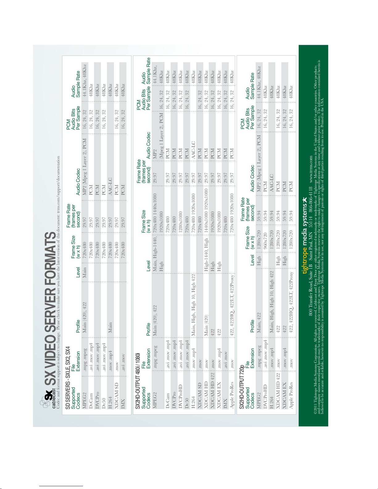
5.1 SX Codec Compatibility List
The Cablecast SX server is designed to play back several video formats. A complete
list can be found in figure 5.1 on the next page.
5.2 Known Issues
There are a few known issues with this release of the Cablecast SX servers (Cablecast software version 5.3.6 Build 221). They are outlined below.
•
Under rare circumstances, noticeable video corruption and audio noise may
be visible on two of the server’s outputs. This situation seems to only occur
after a reboot of the server. To resolve this issue, reboot the server a second
time. We have a lead on a resolution for this issue, and expect it to be resolved
in the future.
5.3 Help and Support
If you have questions about your Cablecast SX server, the Tightrope Media Systems
forum is a great place to seek answers and advice. The forum is monitored closely
by Tightrope staff and many other users who have a wealth of tips and tricks to offer.
To access the forums, point your web browser to http://forums.trms.com
For critical support issues, our technical support team is available via email and
phone. Send requests to [email protected] or call us toll-free at 1-866-866-4118
ex. 250.
23
Page 25
Supported
Codecs
MPEG2
DvCam
DVCPro
Dv50
H.264
XDCAM SD
IMX
.mpg .mpeg
.avi .mov .mp4
.avi .mov .mp4
.avi .mov .mp4
.mov .mp4
.mov
.avi .mov
SD SERVERS - SXLE, SX2, SX4
File
Extension Prole Level
Frame Size
(w x h)
Frame Rate
(frames per
second) Audio Codec
PCM
Audio Bits
Per Sample
Audio
Sample Rate
Main (420), 422
Main
Main 720x480
720x480
720x480
720x480
720x480
720x480
720x480
29.97
29.97
29.97
29.97
29.97
29.97
29.97
MP2 (Mpeg 1 Layer 2), PCM
PCM
PCM
PCM
AAC-LC
PCM
PCM
16, 24, 32
16, 24, 32
16, 24, 32
16, 24, 32
16, 24, 32
16, 24, 32
44.1Khz, 48Khz
48Khz
48Khz
48Khz
48Khz
48Khz
48Khz
800 Transfer Road, Suite 1B Saint Paul, MN 55114 866-866-4118 www.trms.com
Supported
Codecs
SX2HD-OUTPUT 480i / 1080i
File
Extension Prole Level
Frame Size
(w x h)
Frame Rate
(frames per
second)
Supported
Codecs
SX2HD-OUTPUT 720p
File
Extension Prole Level
Frame Size
(w x h)
Frame Rate
(frames per
second) Audio Codec
PCM
Audio Bits
Per Sample
Audio
Sample Rate
High
High
High
1280x720
960x720
1280x720
1280x720
1280x720
1280x720
59.94
59.94
59.94
59.94
59.94
59.94
MP2 (Mpeg 1 Layer 2), PCM
PCM
AAC-LC
PCM
PCM
PCM
16, 24, 32
16, 24, 32
16, 24, 32
16, 24, 32
16, 24, 32
44.1Khz, 48Khz
48Khz
48Khz
48Khz
48Khz
48Khz
MPEG2
DVCProHD
H.264
XDCAM HD 422
XDCAM EX
Apple ProRes
.mpg .mpeg
.avi .mov .mp4
.mov .mp4
.mov
.mov .mp4
.mov
Main, 422
Main, High, High 10, High 422
422
422
422, 422HQ , 422LT, 422Proxy
29.97
29.97
29.97
29.97
29.97
29.97
29.97
29.97
29.97
29.97
29.97
29.97
MPEG2
DvCam
DVCPro
DVCProHD
Dv50
H.264
XDCAM SD
XDCAM HD
XDCAM HD 422
XDCAM EX
IMX
Apple ProRes
.mpg .mpeg
.avi .mov .mp4
.avi .mov .mp4
.avi .mov .mp4
.avi .mov .mp4
.mov .mp4
.mov
.mov
.mov
.mov .mp4
.avi .mov
.mov
Main (420), 422
Main, High, High 10, High 422
Main (420)
422
422
422, 422HQ , 422LT, 422Proxy
Main, High-1440,
High
High-1440, High
High
High
720x480 1440x1080
1920x1080
720x480
720x480
1280x1080
720x480
720x480 1920x1080
720x480
1440x1080 1920x1080
1920x1080
1920x1080
720x480
720x480 1920x1080
Audio Codec
PCM
Audio Bits
Per Sample
Audio
Sample Rate
MP2
(Mpeg 1 Layer 2), PCM
PCM
PCM
PCM
PCM
AAC-LC
PCM
PCM
PCM
PCM
PCM
PCM
16, 24, 32
16, 24, 32
16, 24, 32
16, 24, 32
16, 24, 32
16, 24, 32
16, 24, 32
16, 24, 32
16, 24, 32
16, 24, 32
16, 24, 32
44.1Khz,
48Khz
48Khz
48Khz
48Khz
48Khz
48Khz
48Khz
48Khz
48Khz
48Khz
48Khz
48Khz
SX VIDEO SERVER FORMATS
©2011 Tightrope Media Systems Corporation. All rights are reserved. Cablecast and Front Door are either registered trademarks or trademarks of Tightrope Media Systems in the United States and/or other countries. Other products
and company names mentioned herein may be trademarks of their respective owners. Tightrope Media Systems reserves the right to make changes to specications at any time and without prior notice. The information contained herein is
believed to be accurate and reliable, however no responsibility is assumed by Tightrope Media Systems for its use, nor any infringement of patents or rights of third parties resulting from its use. Printed in the USA.
Codec and format support is subject to change. Please check to make sure you have the latest version of this document: trms.com/support/documentation
FI GU RE 5 .1 : Supported video formats
 Loading...