

Tiger Truck Extended Cab 2019 Service Manual

2019 Extended Cab Truck
- Service Manual -

Content
1. Vehicle Identification ...................................................................................................... 1
2. Main Technical Parameter of the Complete VehicleError! Bookmark not defined.
3. Vehicle Devices & Operation .................................... Error! Bookmark not defined.0
4. Usage of the Vehicle ......................................................................................................... 29
5. Vehicle Oper a t i on Manual ........................................................................................... 35
6. Checkout & Maintenance Service .......................... Error! Bookmark not defined.
7. Malfunction Analyse & Elimination ...................................................................... 57
8. Disposition of Emergency ............................................. Error! Bookmark not defined.
9. Maintenance of the Vehicle ......................................... Error! Bookmark not defined.

Ve hi c le Identification
1. Vehicle Identification
1
车辆标识
1. Identification Number
EQ 1 02 1 GF24Q7
A B C D E
A:Self-Stipulate Code Name
B:Vehicle Catagory Number
C:Main Parameter Code
D:Serial Number of the Product
E:Self-Stipulate Code Name
The VIN should be marked on the
side of the frame beam which is
under the seat that beside the
driver’s, and above the Meter Board
and on the nameplate
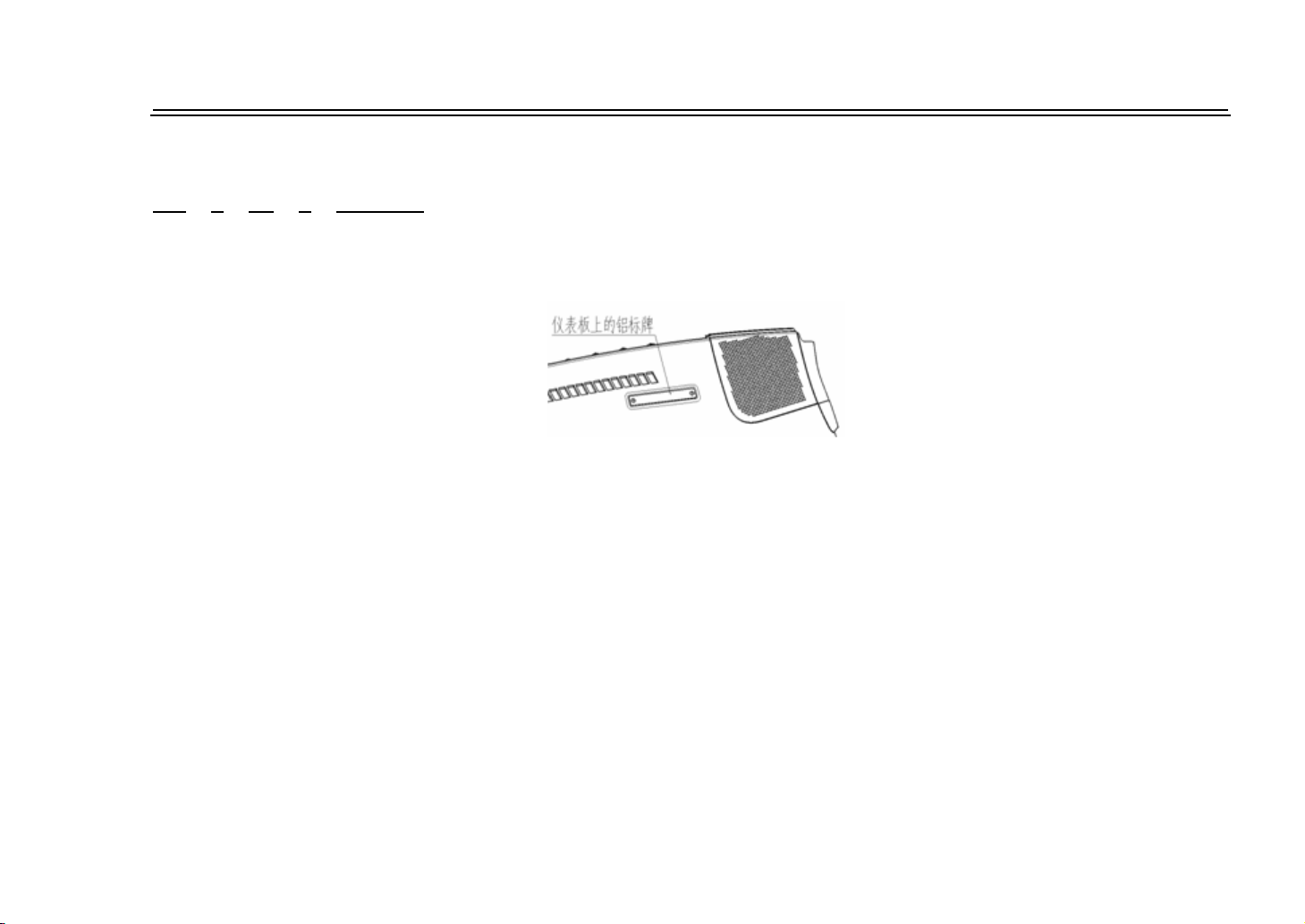
2. VIN
There are two VINs, one is on the
aluminum plate which is on the right
front side of the meter, the other is
on the body which is under the front
row right side seat.
3. Serial Number of the
Engine
The serial number of the Engine
should be marked on the convexity
of the rear lower part of the right
cylinder.
2

Main Technical Parameter of the Complete Vehicle
2. Main Technical Parameter of the
Complete Vehicle
3
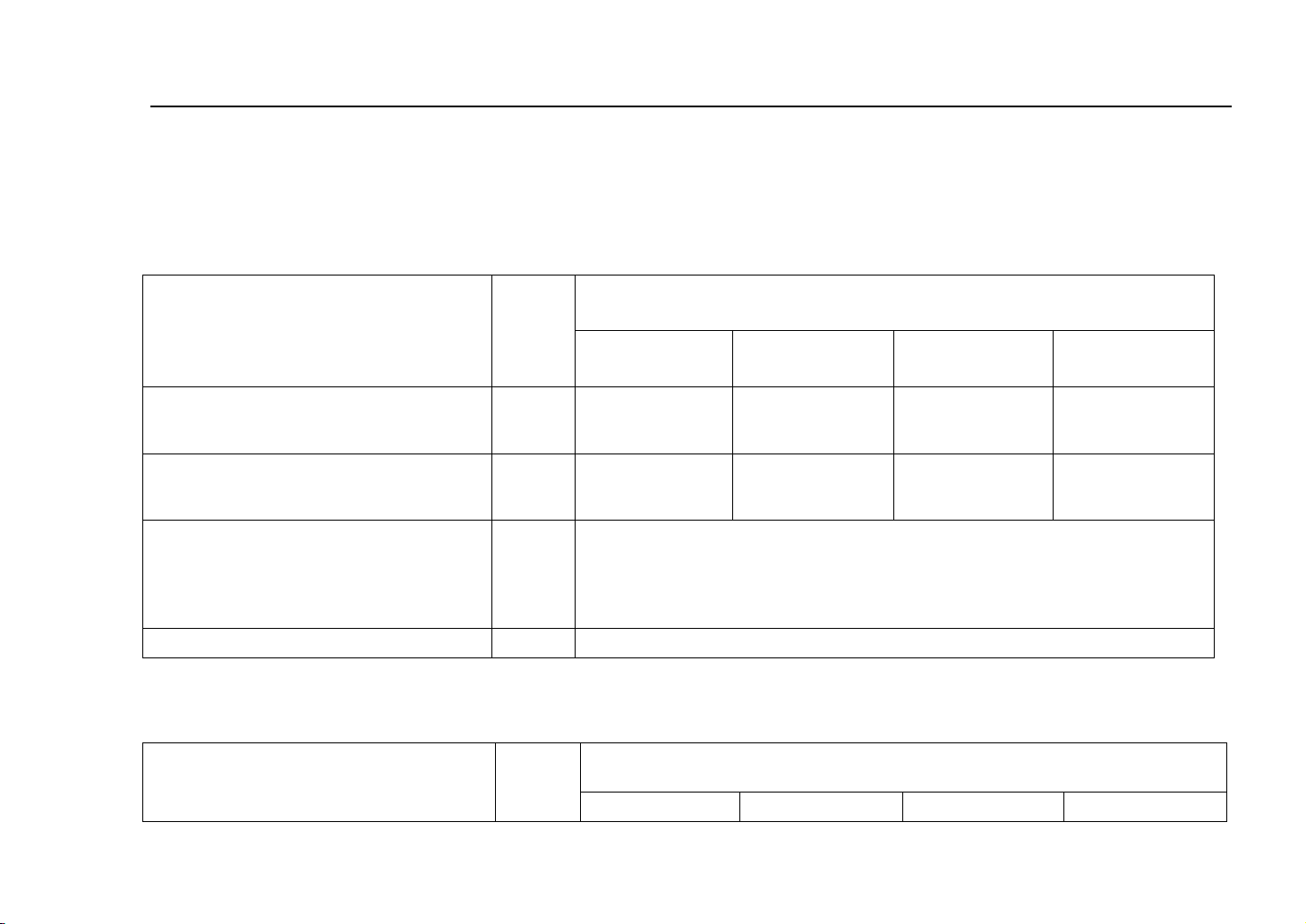
Main Technical Parameter of the Complete Vehicle
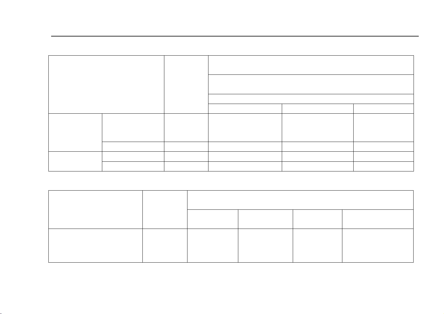
Items
Unit
Optional Engines of EQ1021GF24Q7
BG13-20
/EQ474i
AF10-06
/EQ465i-21
BG10-01
DK12-01
Max. Speed
km/h
135
110
120
130
Gradibility
%
33.1
25.4/24.6
27.9
42.3
Brake Distance at 50km/h(full
loading)
m
≤20
Any part of the vehicle shall not exceed the width of the trial driveway,
that is 2.5 M.
MinmumTurning Diameter
m
10.3
Items
Unit
Optional Engines of EQ1021GF24Q7
BG13-20
AF10-06
BG10-01
DK12-01
1. Parameter of the Engine
Please see the instruction manual of engine along with the vehicle
2. General Performance Index
3. Fuel Ecomomy
4
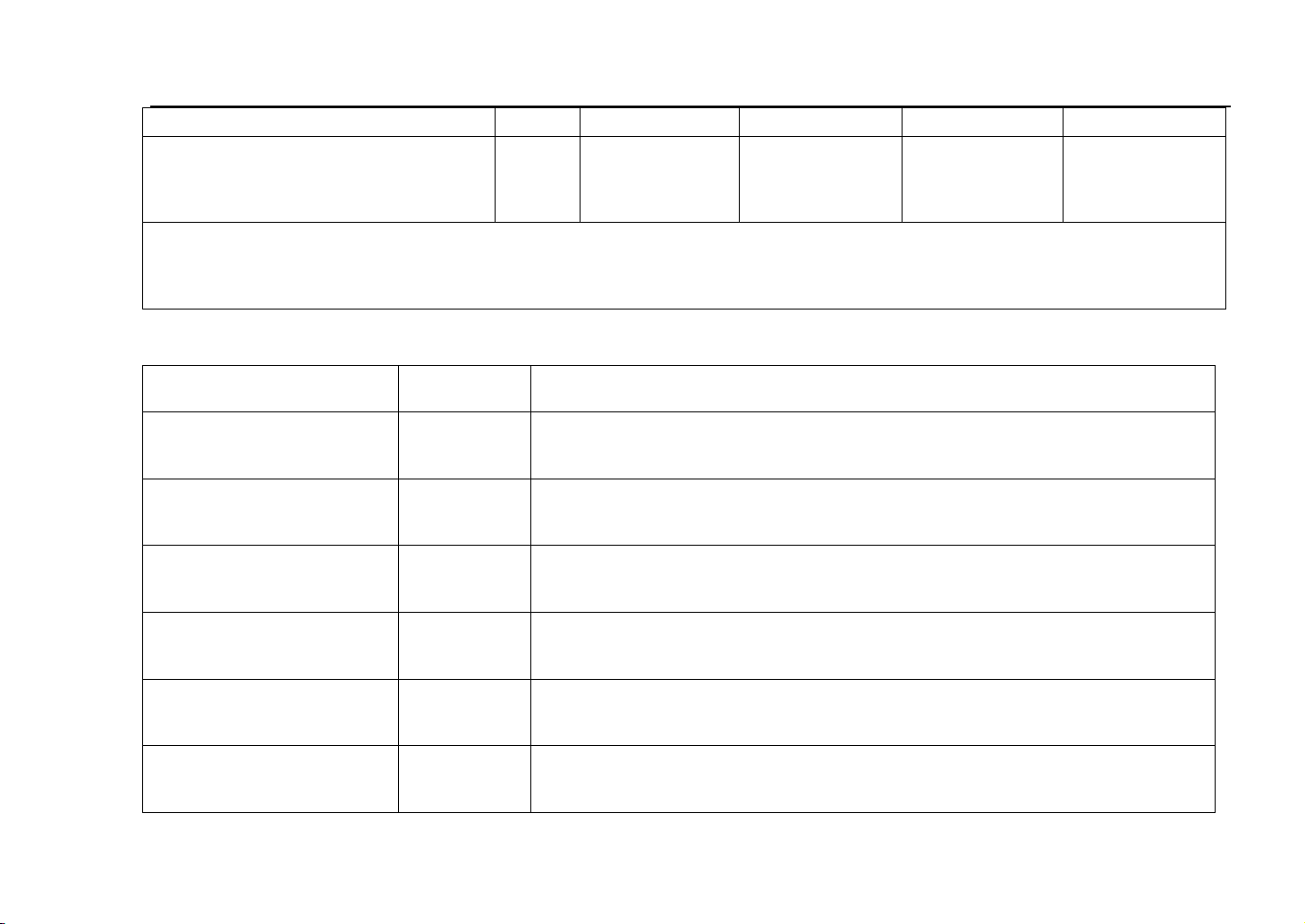
/EQ474i
/EQ465i-21
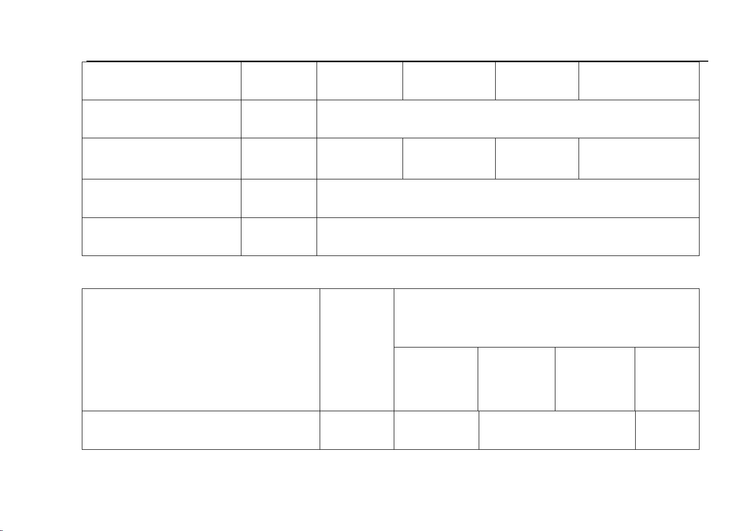
* Fuel Consumption per 100 km
(60km/h)
L/100
km
5.3
4.9/5.2
5.1
5.1
* Note: The real fuel consumption will be higher than this numerical value for different use conditions.
4. Main Dimensions
Items
Unit
Vlalue
Total Length
mm
4280±20
Total Width
mm
1560±10
Total Height(Unladen)
mm
1880±15(W/O Guardrail 1850±15)
Wheel Space
mm
2760±15
Front Track
mm
1310
Rear Track
mm
1310
Main Technical Parameter of the Complete Vehicle
5
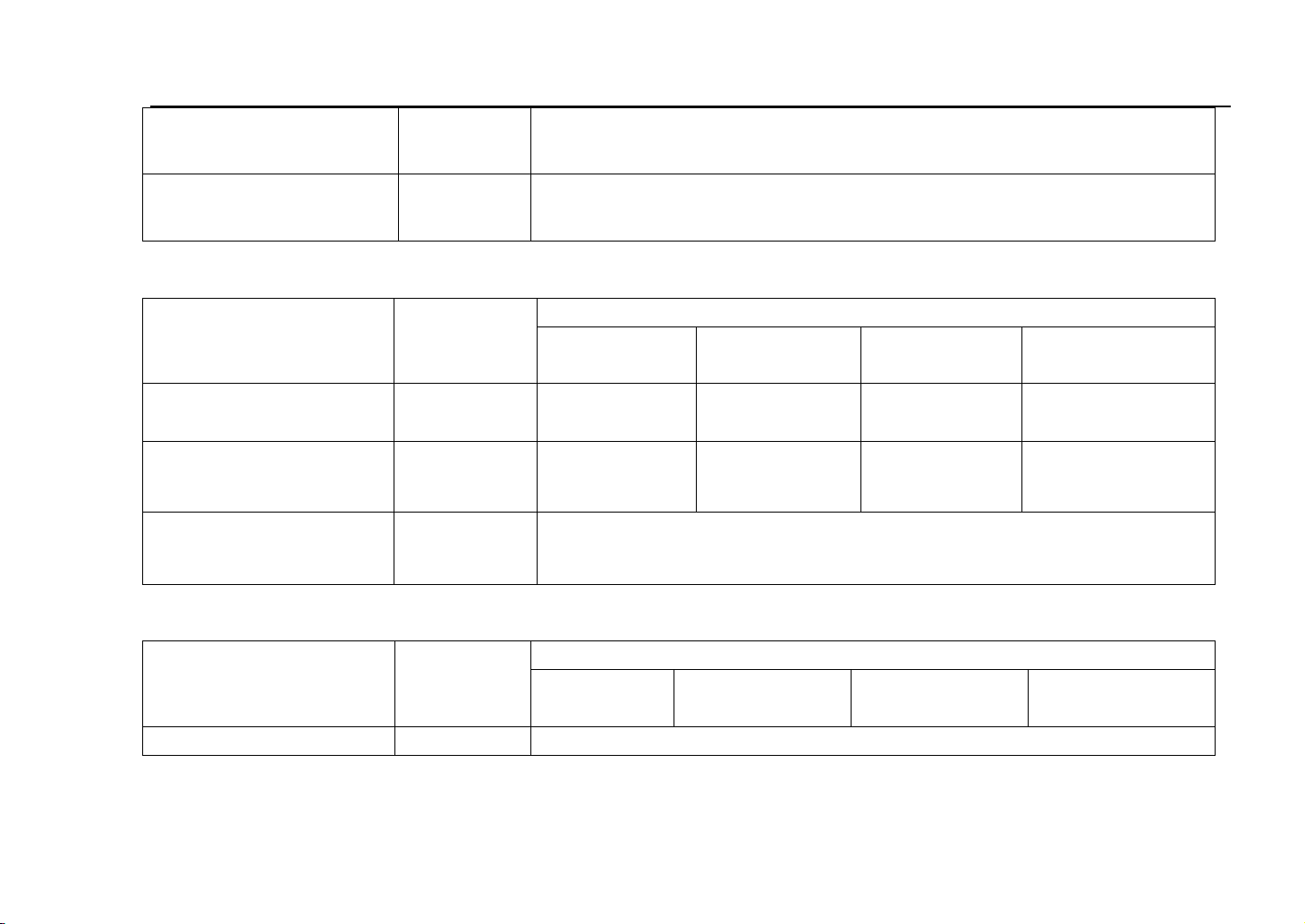
Main Technical Parameter of the Complete Vehicle
Front Overhang
mm
580±10
Rear Overhang
mm
940±10
Items
Unit
Optional Engines of EQ1021GF24Q7
BG13-20
/EQ474i
AF10-06
/EQ465i-21
BG10-01
DK12-01
Kerb Weight
kg
940
930
930
940
Gross Weight
kg
1665
1655
1655
1665
Passenger/ Rating Loading
Capacity
Pax/kg
2(Include drive)/595
Item
Unit
Optional Engines for EQ1021GF24Q7
BG13-20
/EQ474i
AF10-06
/EQ465i-21
BG10-01
DK12-01
Toe-in
mm
0.108(0~5)
5. Main Quality Parameter
6. Toe -in Parameter
6
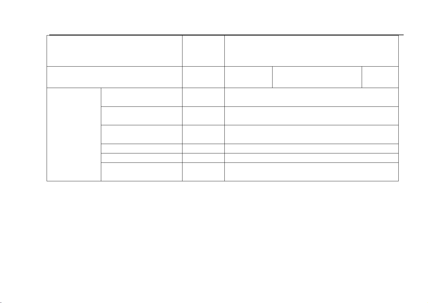
7. Tire Pressure
Item
Unit
Optional Engines for EQ1021GF24Q7
BG13-20/AF10-06/BG10-01/DK12-01/EQ474i /EQ465i-21
Optional Tire for EQ1021GF24Q7
165/70R14
165R13LT
155R13LT
Front Tire
Unladen
kPa
180
200
200
Fully Loaded
kPa
220
240
240
Rear Tire
Unladen
kPa
200
220
220
Fully Loaded
kPa
250
300
375
Items
Unit
Optional Engines of EQ1021GF24Q7
BG13-20
/EQ474i
AF10-06
/EQ465i-21
BG10-01
DK12-01
Cooling System of Engine
L
5.5
4.5
4.5
5.5
8. Capacity Data
Main Technical Parameter of the Complete Vehicle
7
Lubricating System of
Engine
L
4.2~4.5
3.2
3.2
3
Fuel Tank
L
40
Lubricating Oil of Gear-Box
L
1.3~1.5
1.3
1.3
1.3±0.15
Rear axle lubricating oil
L
1.2
Brake Fluid
L
0.6
9. Cooling System Data
Item
Unit
Optional Engines of EQ1021GF24Q7
BG13-20
/EQ474i
AF10-06
/EQ465i-211
BG10-01
DK12-01
Capacity of Refrigerating
W
7200
5350
7200
Main Technical Parameter of the Complete Vehicle
8
Main Technical Parameter of the Complete Vehicle
Wind Speed while Refrigerating
M3/h
≥400
Consumption Power of the Compressor
W(Nc2000r/
min)
3430
2610
3430
Control
Parameters
Automatic Increase of
Idle Speed
r/min
1100±50
A/C Water Tempreture
Protection
℃
110
Engine Water
Tempreture Protection
℃
90
High Pressure Protection
MPa
3.2
Low Pressure Protection
MPa
0.2
Overheating Protection ℃ 150±5
9

Ve hi c le De v ic es & O pe r at i on
3. Vehicle Devices & Operation
10
Ve hi c le De v ic es & O pe r at i on
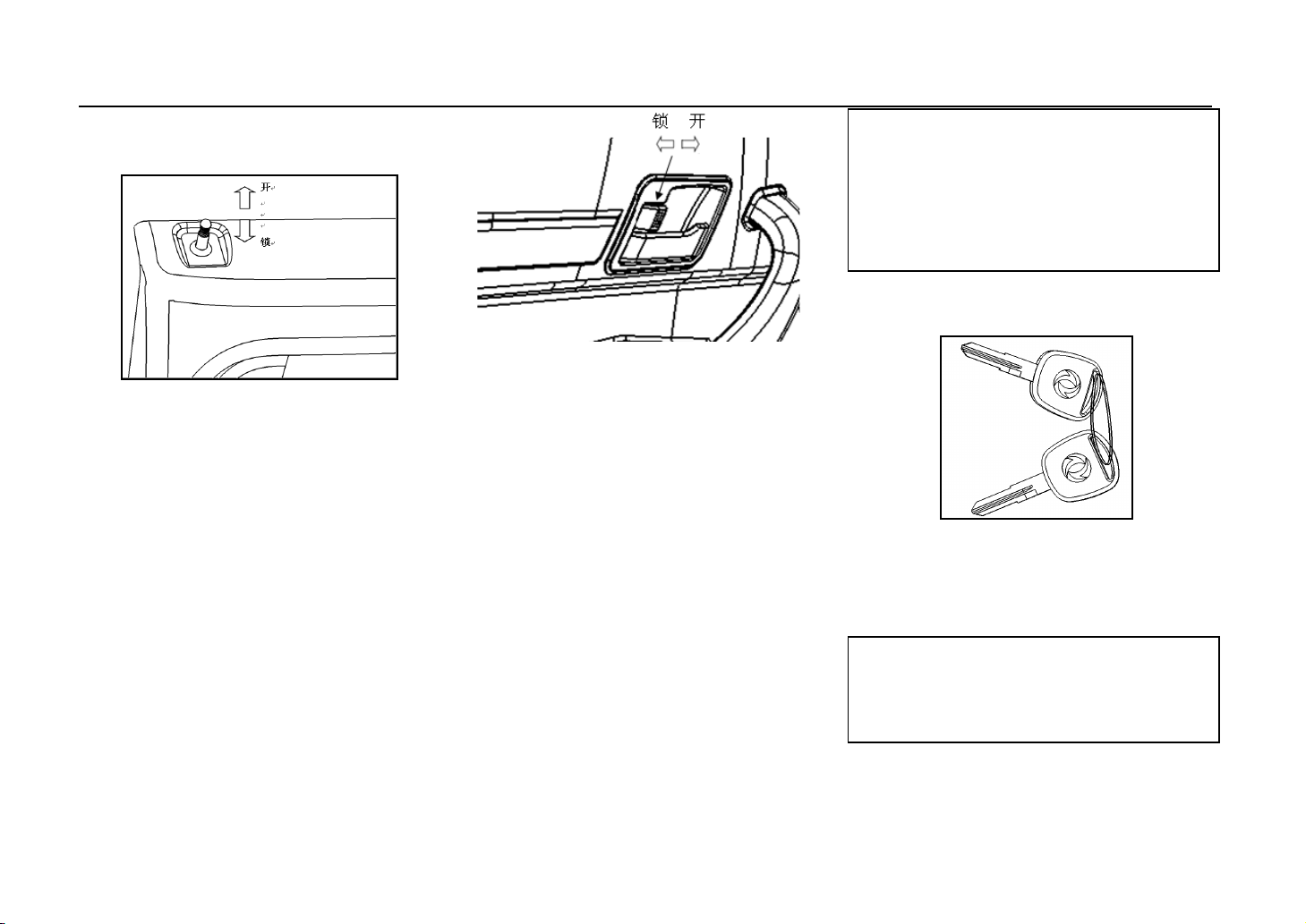
1. Front Door
①
Inside of the Vehicle
All the doors can be locked by pressing
down the locked button. After that, one
cannot open the door either inside or
outside the vehicle. When open, pull the
locked button upward.
The front door can be opened or locked
by keys. While open, the locked button
up; while locking, the locked button
down.
②
Inside of the Vehicle
All the doors can be locked by pressing
down the locked button. After that, one
cannot open the door either inside or
outside the vehicle. When open, pull the
locked button out.
The front door can be opened or locked
by keys. While open, the locked button
out; while locking, the locked button
press down.
Note:
Press down the locked button while the
vehicle running ,the door should be
locked safely to prevent the door
opening accidently.
2. Keys
This vehicle equipped with two keys,
please keep one in a safe place for spare
use.This key can be used for ignition
switch, front door and fuel cover.
Note:
Please keep the key along with you at
any time.
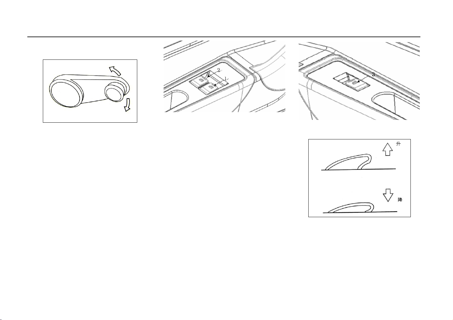
3. Rocking window outfit by
11
Ve hi c le De v ic es & O pe r at i on
hand
There are two kinds of rocking window
outfit: by hand and by electric.
When by hand, there is handlebar on the
inner side of the door. Turn the
handlebar clockwise or
counter-clockwise, the door window
will come up or come down.
When by electric, there is a button on
the inner side of the door.
Button One: Electrical Riser Button on
Button Two: Riser Button for door
4. Rocking window outfit by
Button Three: Electrical Riser Button on
electric
the driver’s side to control
the door window of the
copilot.
window on the side of the
driver.
side of Copilot.
Pull the button up, the door window will
be closed, press the button down, the
door window will be open.
12
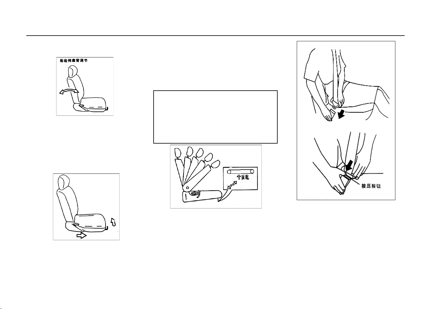
5. Seat
Front Row Seat
The fixing of the front row seat is just
like the picture below, make the two
pothooks hook the button, and then
fasten it.
Ve hi c le De v ic es & O pe r at i on
the required position; pull the backrest
adjusting handlebar beside the seat, the
backrest will turing automatically, then
loose the handlebar, the backrest will be
fixed in the position. And the backrest
can be folded forward.
Note:
Do not adjust the driver’s seat while
driving, otherwise, the seat may move
forward or backword abruptly which
may cause driver lose its control.
Adjustment of the front row seat: Pull
the sliding adjusting handlebar which is
under the seat up, the seat will slide to
6. Safety Belt
The safety belt of the front row seat is
automatic contraction.While using,
please pull out the lock tongue which
connect the safety belt and wing your
body and pass, then push the lock
13
tongue to the lock catch until hear the
“clatter” sound.
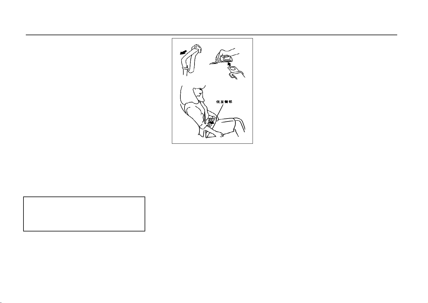
The length adjustment of the saftety belt
is very important. While adjusting the
lap belt, please check the lock at the
meantime to make sure that it has been
locked, and then pull up the shoulder
belt till the lap belt being buckled tightly.
The length of the safety belt can be
adjusted freely according to different
requirements.While undo the safety belt;
press the release button on the lock
catch.
The customers should not do any
amendments; otherwise it may cause the
safety belt not being adjusted which will
influence elasticity.
Note:
While driving, please wear the safety
belt.
Ve hi c le De v ic es & O pe r at i on
The safety belt is designed according to
the structure human body skeleton, (See
the picture). Please note that, the waise
band part shall not be across the
abdomen.
The adjustment of the safety belt is not
only reliable and comfortable but also
can help to make safer. Flexible safety
belt will influence its protection
function.
Safety belt should be prevented from
polishing compound, grease spot,
chemical article, especially storage
battery sour liquid polluted. While
washing, you can use neutral soap and
water. If the safety belt is worn and torn,
polluted or damaged, should be
changed.
It is very important that when the safety
belt impacted fiercely, though it is not
obvious, it should be changed.
Do not use the deformed saferty belt.
One safety belt is only for one person,
tie the children on knee of passenger to
the safety bealt is very dangerous.
The position of lock limit position
should not interfere or block the safety
belt fully withdraw.
14
Ve hi c le De v ic es & O pe r at i on
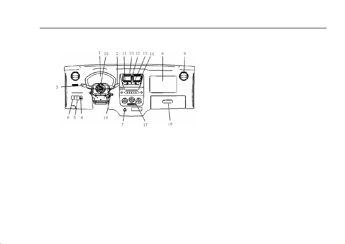
仪表板
7.
1. Assembled Meter
2. Wiper & Syringe Switch
3. Lighting/Turning and high/low beam converting switch
4. Head lamp control switch
Meter Board
6. Rear Foglam
7. Cigarette Lighter
8. Auxiliary Frame Air Bag
9. Side Intake
10. Centre Intake
11. A/C Switch
12. Switch Assy Defroster
13. Rear fog Switch
14. Fog Switch
15. Emergency Switch
16. Tool Box
17. Control Board for Heating
18. Ignition Switch
5. Rear Foglam
15
Ve hi c le De v ic es & O pe r at i on
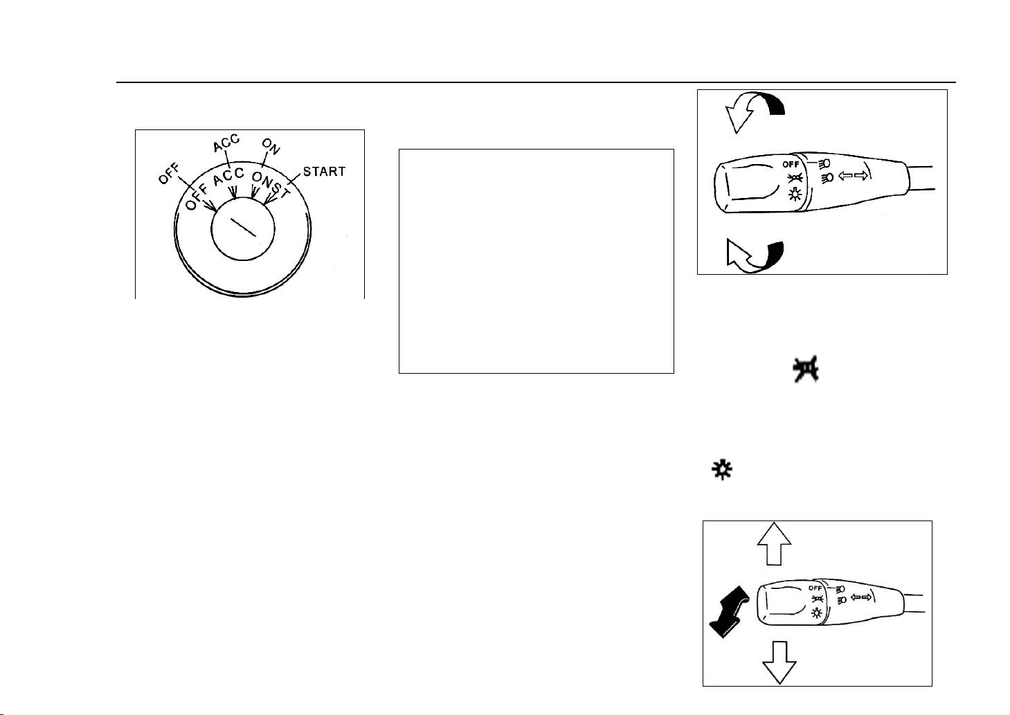
8. Ignition Switch
1. ‘Off’: the auxiliary equipments
don’t work, only head lamp and horn
work, and the key can be pull out only
in this position.
2. ‘ACC’: assisitant equipments
(radio & cigar lighter) work and the
engine don’t work.
3. ‘On’: while at this position,
all the wiring can be put through and
the engine prepares to run.
4. ‘Start’: On this position, the
engine is started by the starter, once
the engine starts. Please loose the key
which will return to ‘on’automatically.
Do not keep the ignition key
in’ON’position for a long time unless
the engine is running, or else, the
battery will discharge.
Note:
The working time for starter shall not
exceed 5 seconds. If the engine cannot
be started, please wait at least five to
ten seconds, and try again. If the
engine fail to start after several times,
please check the fuel power supply
system or pay a visit to the
Maintanence Stop of Dongfeng Sokon
Vehicle.
9. Lighting, Turning and
High/Low Beam Control Pole
① Lighting Switch: there are three
places, ‘off’means all lights being
turned off; ‘ ’means front small
lights, tail lamp, liscence lamp and
light for meter being turned on;
‘ ’means the headlights being
turned on.
16
Ve hi c le De v ic es & O pe r at i on
② Turning signal light switch:
While the ignition key is in the
position in “ON ", it can send off
signal by turning control lever forward
and backward. Pull the control lever
forward from the middle position and
then the right turning light glitter; pull
the control lever backward and then
the left turning light flickers. The
control lever gets back to the middle
position automatically after turning.
③ Far, near light button: Put the light
switch in “headlight " position.
Pressing down is the far light, getting
back to middle position is the near
light, and lifting the control lever up,
the headlight glimmers (overtake).
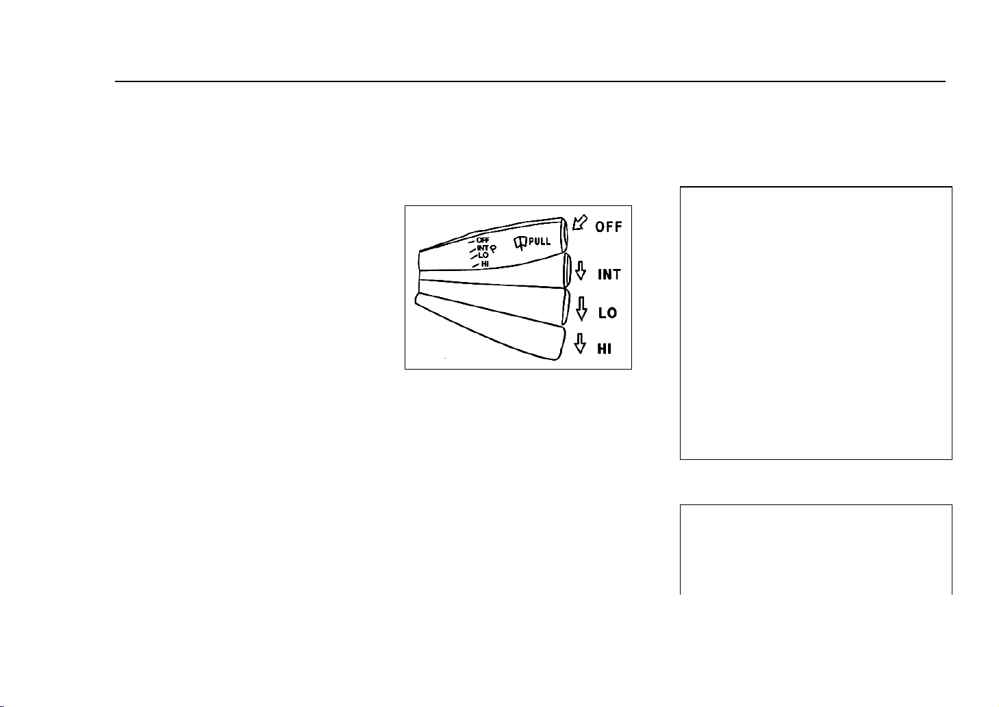
10. Wiper & Cleanser
Control Pole
The control lever is on the right of the
steering wheel, and the control lever
has four gears:
INT:Wiper is the intermission gear,
which is suitable for fogy and rainy
day.
LO: The wiper will run at stable and
low speed.
HIGH: Wiper will run at a stable
high speed.
OFF: Wiper will stop running.
Pull back the control lever, it can jet
cleaning liquid.
Note:
When the cleanser stop spraying,
should release control lever, turn on
the washing device switch when have
no cleaning liquid, then the electric
machine will be damaged. If attempt
to remove the dust on the dry
windscreen glass with the wiper,
windscreen glass and wiper will be
damaged. You should drench the
windscreen glass with the cleanser
first, and then open the wiper.
Note:
In windscreen glass frozen cold
weather, you should remove ice and
snow of the arm first, make the defrost
17
device to put through, and then use the
shave.
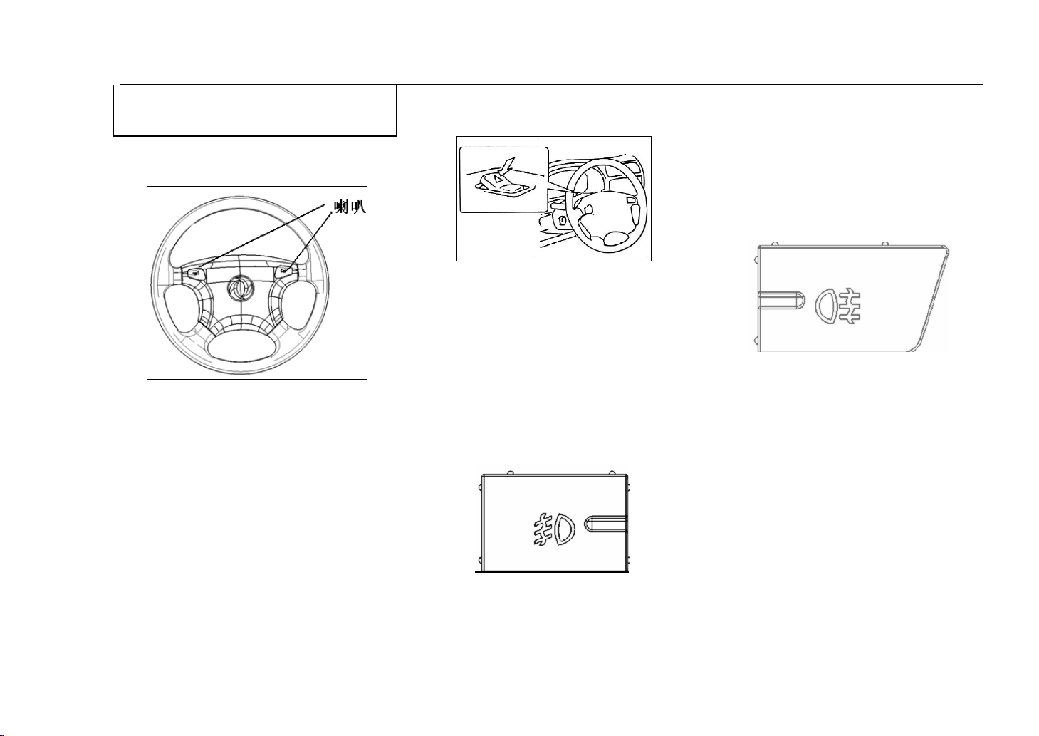
11. Horn
Wherever the ignition switch is, when
you press the horn button, it can
sound.
The horn button is on the steering
wheel:
Ve hi c le De v ic es & O pe r at i on
12. Emergency Switch
Press down the button, all the four
turning lights and the side turning
lights glitter simultaneously. Press the
other end will turn off the lights.
This switch is only used for
emergency situation and running in
abnormal situation.
13. Foglight Switch
second gear, and press the foglight
switch, the foglight will be turned on,
and so will the indicator light; press
again, the foglight is turned off, so is
the indicator light.
Rear Foglight
Turn the headlight switch to the
second gear, and press the foglight
switch, the foglight will be turned on,
and so will the indicator light; press
again, the foglight is turned off, so is
the indicator light.
① The horn button is in the centre of
the the three widths steering wheel.
② The horn button is on the side of
the square width steering wheel
Front Foglight:
Turn the headlight switch to the
18
Ve hi c le De v ic es & O pe r at i on
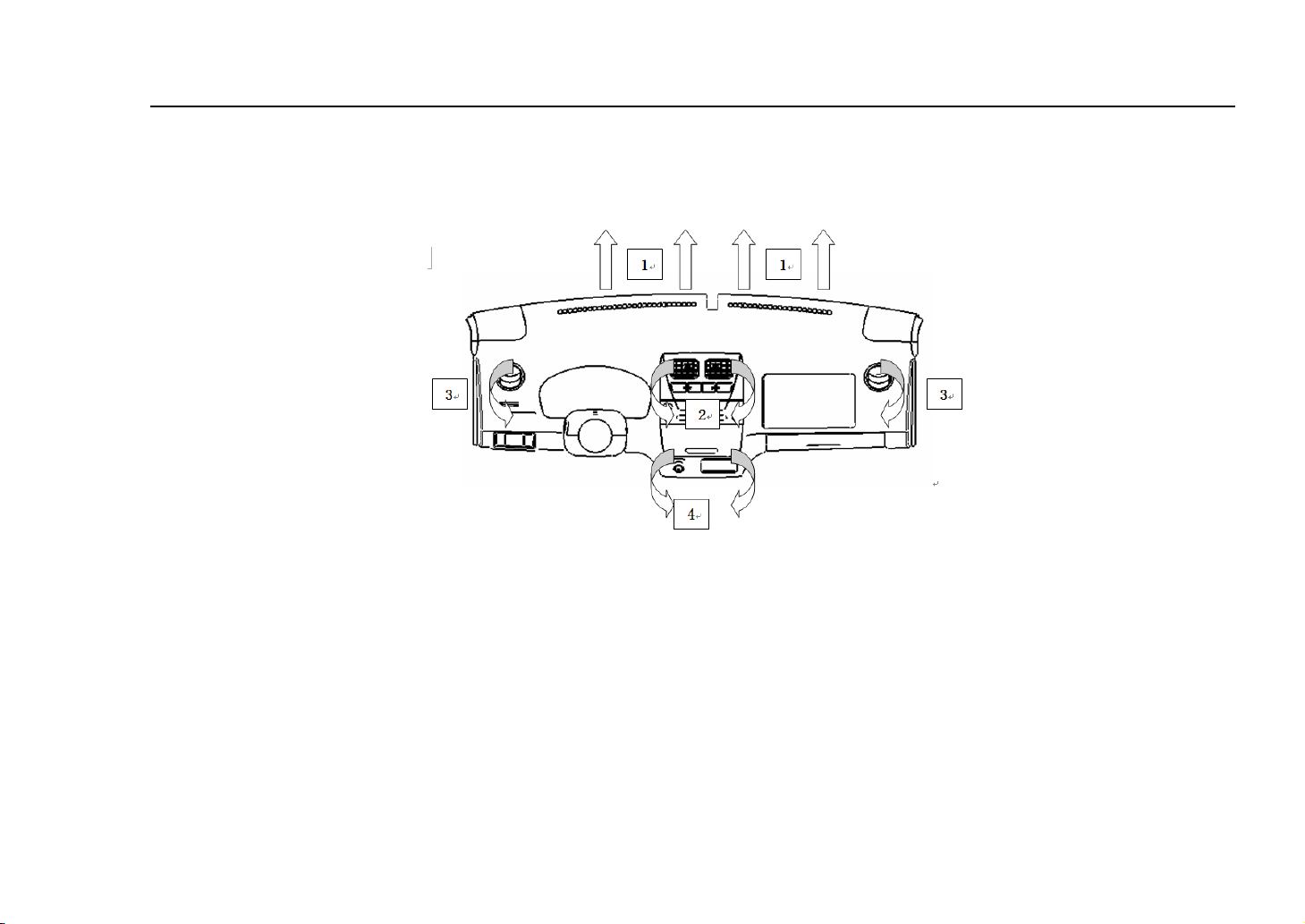
14. Heating System
The heating system to provide heating, defrosting and ventilation funvtion.
① Windshield defrosting air door
② The central vent hole
③ The side defrost vent hole
④ The broad vent hole
19
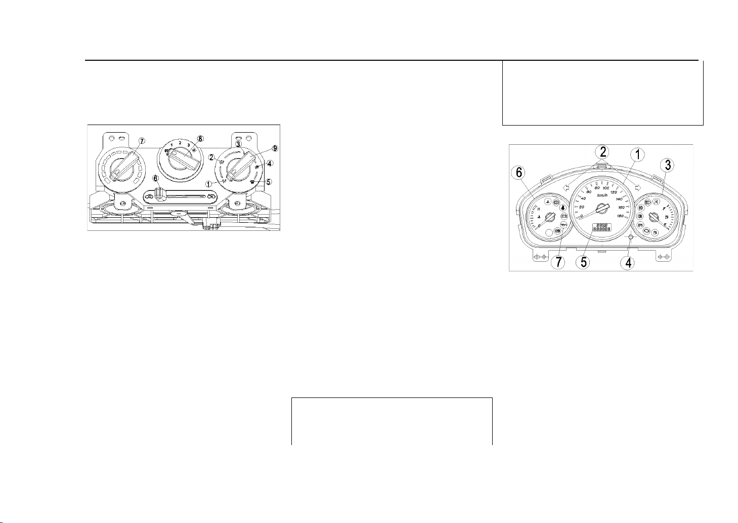
15. Control Board of Heating
System
Ve hi c le De v ic es & O pe r at i on
④ Defrost & Warm Air
Warm air is sent off from the exhaust
port on the floor, some is sent off from
the defrost exthaust port of windscreen
and side defrost exhaust port.
⑤ Defrost
⑥ Cycle Control Button of
Inside & Outside
Control the circulation of the air of
inside & outside.
circulation so as to avoid the air in the
vehicle too dirty and the windpane
will become humidity and with low
thickness oxygen.
16. Assembled Meter
① The wind is sent off through
the intake in the centre of the the
meter board or through side
ventilation.
② Sending off air in both
directions: Cold air is sent off from the
centre intake, and the warm air is sent
off from the bottom intake.
③ War m A ir
Warm air is sent off from the exhaust
port on the floor.
⑦ Tempreture co ntrol button
Control the tempreture of cold &
warm air (blue is cold air, and red is
warm air)
⑧ Draft Control Button
Control the rotate speed of fan, that is,
adjust the draft.
⑨ Optional Button for
Ve nt i la t e Po s it i on
Note:
The time for blowing should not be
too long while the air is in inner
(The picture is just for reference)
① Speedometer
② Left & Right turning
indicator light
③ Fuel Gauge
④ Return Button for Odomet
⑤ Indicating instrument
⑥ Wate r The rmo mete r
20

⑦ Function Indicator Light
Speedometer
Ve hi c le De v ic es & O pe r at i on
Odometer after finishing caculation ,
count again since " 0 " , analogize
sequentially to count for the first time.
Note:
Pay attention to the running mileage,
and maintain the vehicle according to
this instruction manual..
Water Thermometer
exceeds the scope, it means the engine
too hot, you should stop the vehicle.
Fuel Gauge
The speedometer expresses with km/h
the speed of the automobile.
Odometer
The odometer has six -figure number
in all to show the total driving mileage,
the minimum unit of mileage is 1km.
While driving, the water tempreture
should be kept in the normal scope,
that is: between ‘C’& ‘H’. When the
pointer moves to ‘H’direction and
While the pointer at the ‘F’position, it
shows that the fuel tank is full of fuel;
while at the position of ‘E’, it shows
the fuel tank is empty
Left & Right turning
indicator light
21
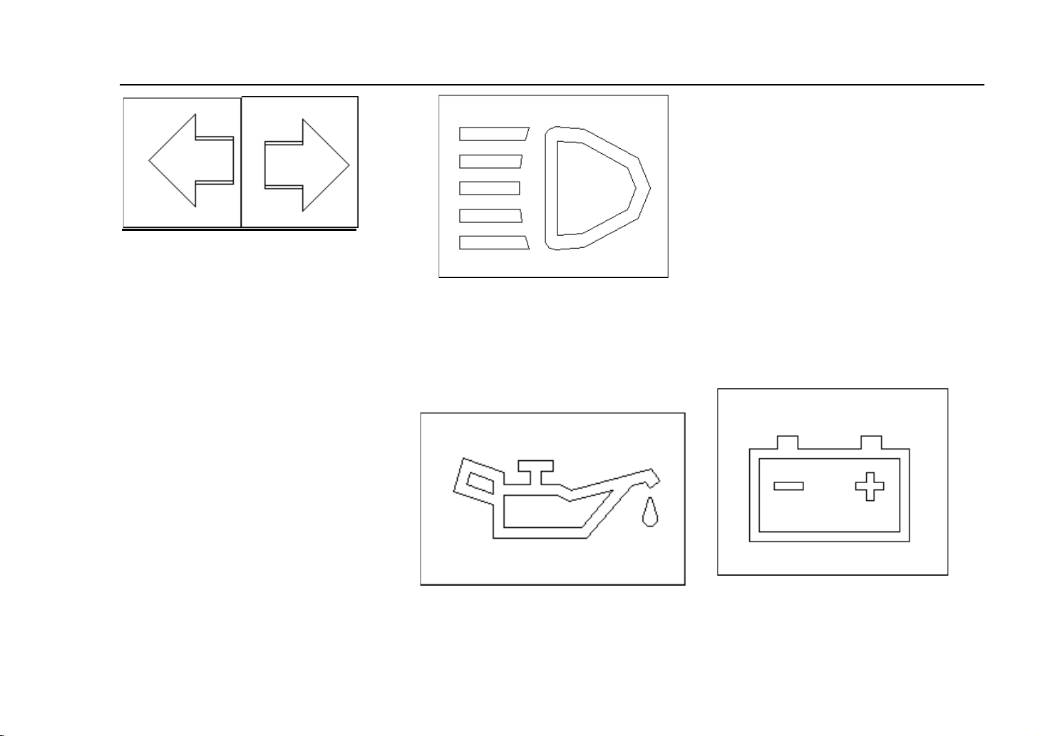
When the ignition switch is on the
position of turn-on, making the
turning switch gets through, the
indicator light will flicker and the
turning light turns on showing turning
signal given. Turning left, the left
indicator light turns on; turning right,
the right indicator light turns on.
High beam indicator light
Ve hi c le De v ic es & O pe r at i on
When every headlight adopts high
beam or dipped headlight, this
indicator light will be on.
Sump, pressure, indicator
light
after the engine is started, it will go
out immediately. Otherwise it shows
the oil level of the bottom shell of the
engine passes low or the lubricating
system breaks down, please make the
engine go out and carry on the oil
level check and annotate immediately.
If fail to fix a breakdown yet, please
go on an all-round way checking of
lubricating system or get in touch.with
the local distributors or Dongfeng
Sokon Maintenance Department.
Charge Indicator Light
When putting ignition switch through,
this indicator lamp lights immediately,
When ignition switch puts through,
this indicator lamp lights immediately,
22
and engine goes out immediately after
starting. Otherwise it shows the
battery charge system breaking down,
please check if the fan belt ruptures or
relaxes at first, if normal, carry on
circuit check again or get in
touch.with the distributor or Dongfeng
Sokon Maintenance Department.
Ve hi c le De v ic es & O pe r at i on
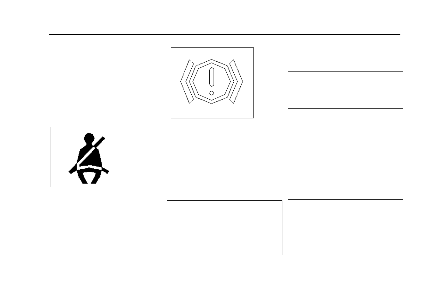
Indicator Light
indicator puts through abnormally
while driving. If on these cases, please
ask the Dongfeng Sokon
Maintenance Department for help.
When the indicator light puts through
abnormally, please bear the vehicle off
the road and test the brake system on
the roadside.
Safety Belt Indicator Light
In normal cases, when the ignition
switch in ‘ON’ or " START "
position, the light is on , and it will go
out after the engine starts.when the
liquid level of the container of brake
liquid is lower than the fixed liquid
level, the light will be on. And it will
When the ignition switch puts through,
this indicator light will be on and will
be out after the safety button inserting
into the safety belt fixing housing
which shows the safety belt has been
well buttoned.
Brake, Liquid, Position
be out after adding brake liquid
according to the regulation.
Note:
It shows the brake system breaks
down when the ignition switch is on
the position of ‘ON’or ‘START’ but
the indicator light is not on or it is not
out after the engine starts or the
Note:
At this situation, it necessary to need
longer parking distance, more
powerful pedal force and longer pedal
stroke.
After test, please drive the vehicle to
the nearest maintenance stop at low
speed if you believe it is safe for do
so. Otherwise please trailer it to the
maintenance stop.
Engine, Trouble, Indicator
Light
23
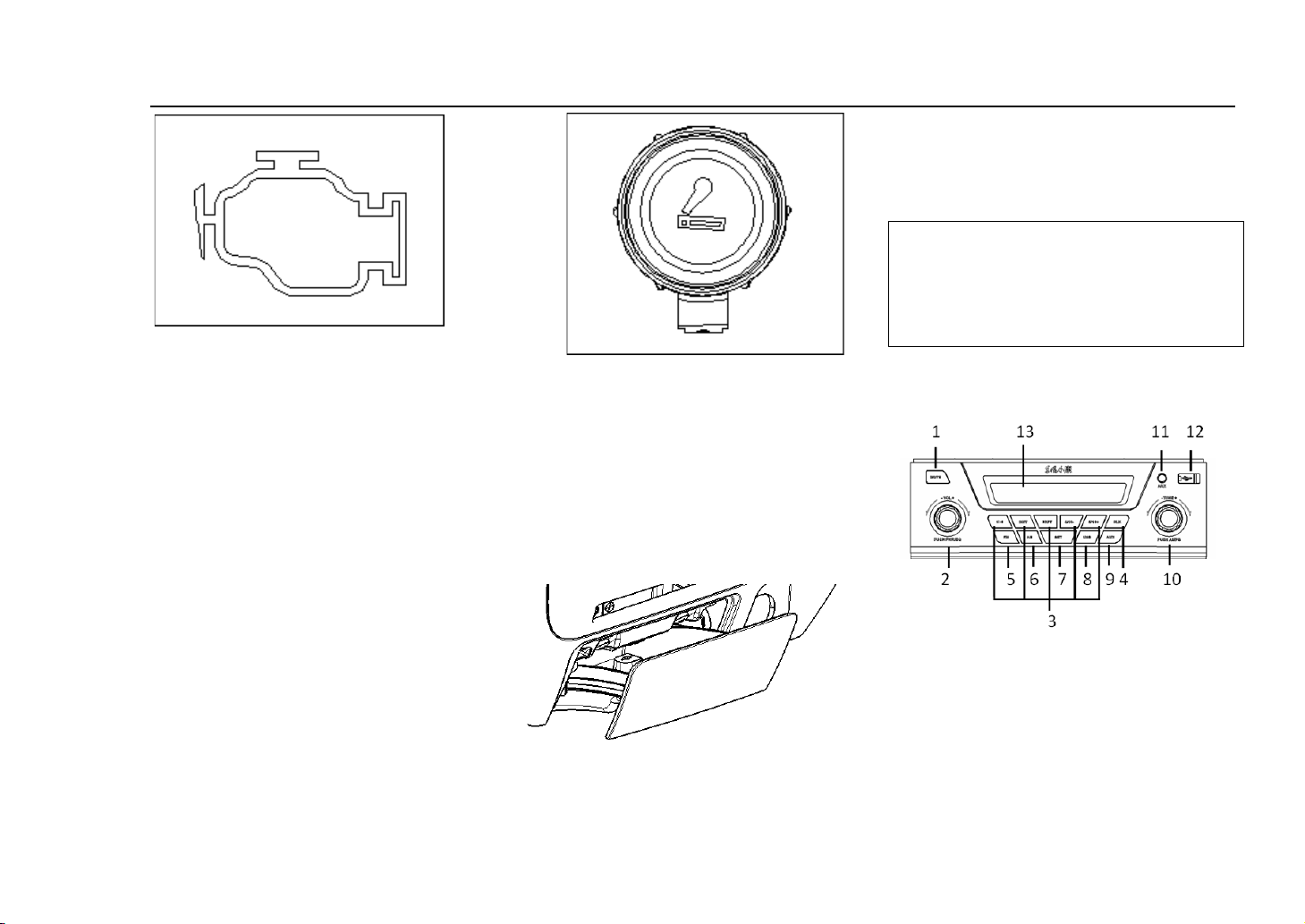
When the ignition switch is in the
position of ‘ON’, the trouble lamp will
be on, it shows the the trouble lamp
circuit is normal.
After the engine is started, the trouble
indicator lamp will go out, if the
trouble indicator lamp does not go out
while the vehicle starts or lights in the
course of running, it shows the engine
control module breaks down , please
ask Dongfeng Sokon Maintainer for
help.
Ve hi c le De v ic es & O pe r at i on
cigarette ash, push it downwards, then
totally pull out from the socket
outwards. Push the ash box along the
guide while putting.
Note:
The cigarette end should be put into
the ash box after putting it out so as
not to cause fire.
Press the cigarette lighter button, wait
several seconds and the resistance
wire will turn red and hot, and it can
be taken out to use after it
automatically rebounds to its original
position.
18. Cigarette Ash Box
19. MP3 & Radio
(The picture is just for reference)
17. Cigar Lighter
The ash box can be used after being
pulled out, while clearing up the
(1)MUTE
(2)On-Off/ Sound Effect Knob
(3) Number Button
(4) Clock Set Button
24
(5) FM Button
(6) AM Button
(7)SET Button
(8) USB Button
(9)AUX Button
(10)AS/PS Knob
(11)AUX
Ve hi c le De v ic es & O pe r at i on
Tool box by hand undraw handle may
be unlock tool box , interior
placement a little thing.
(12)USB
(13) Screen
20. TOOL BOX
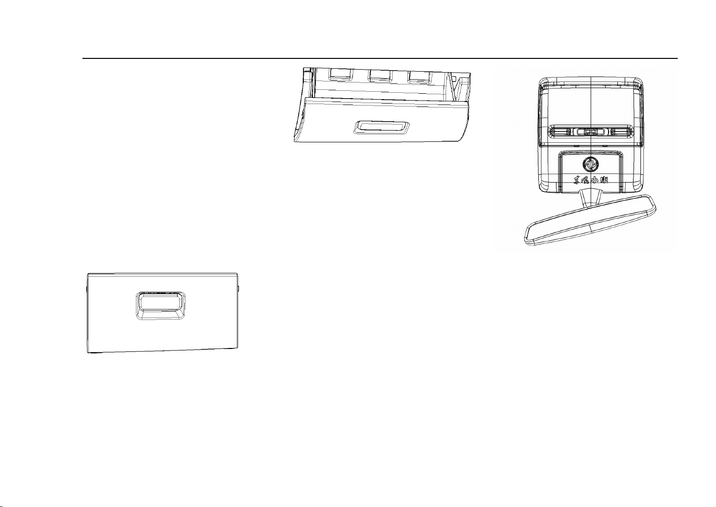
21. Interior Light & Inner
Rear View Mirror
The indoor light button consists of
three pieces of shelf location.
“OFF" is closed.
“DOOR “means switch at the door,
when the button is in this shelf, the
light is not on while closing the door,
and the light is on while opening the
door. As any door is closed
uncompletely, this light will not go
out.
“ON” means being turned on, while at
25
this shelf, the inside light will be on.
Ve hi c le De v ic es & O pe r at i on
The sunshading board can rotate up
and down by winding its pivot. While
adjusting, place hands close to both
ends of the mount ing pad and rotate.
There is a small mirror on the back of
sunshading board which is on one side
Look at the light inside and regard
mirror as succeeding in all inside, and
it is set up in the middle of the top of
wind window.
Inner view mirror can rotate from side
to side up and down along central axle;
and park it at the any position inside.
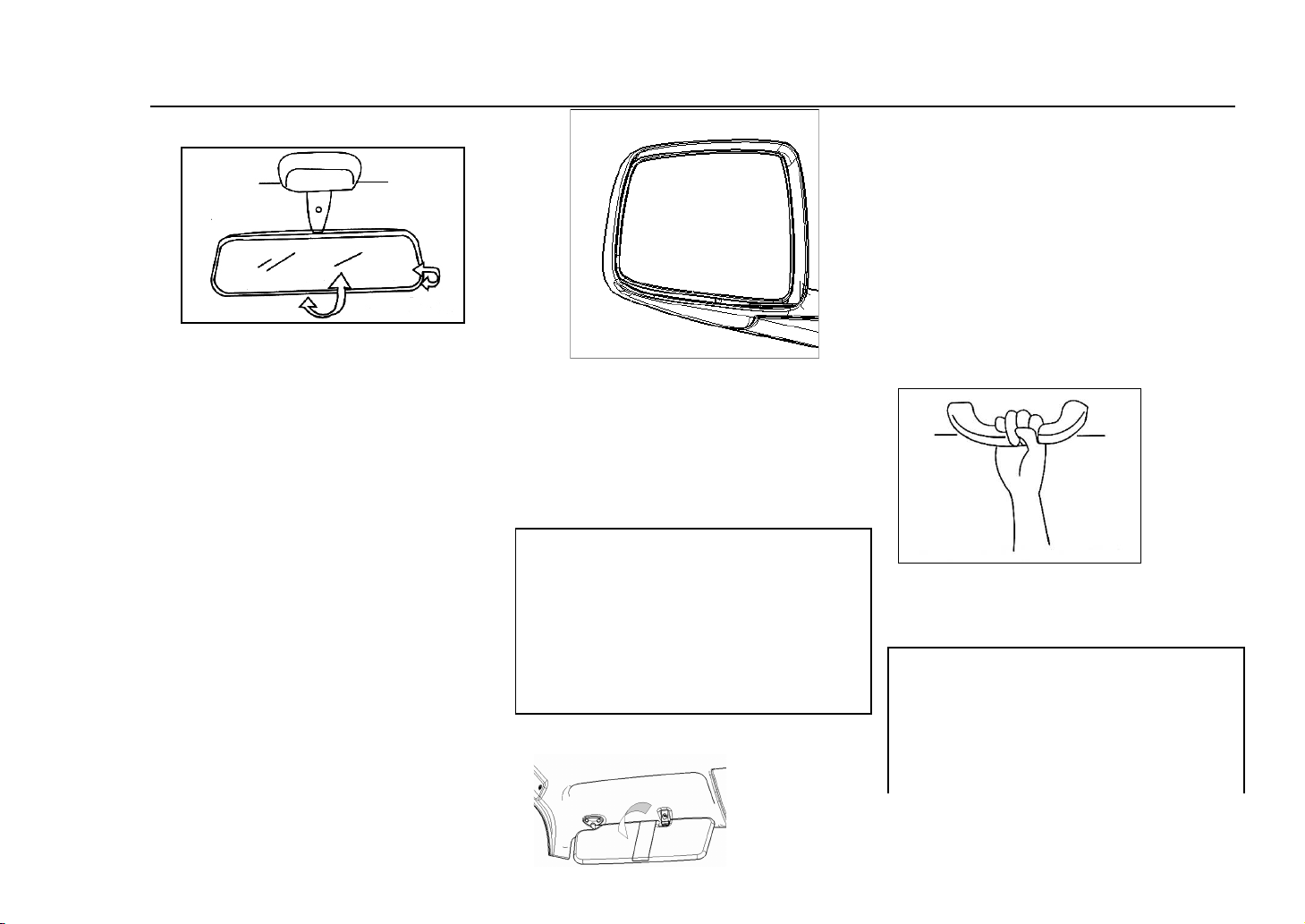
22. Outer rear-view Mirror
Adjust the outer rear-view mirror
according to your demands making
that you can see the behind vehicles or
other objects through it. And the
surface of the outer rear-view mirror is
protruding surface.
Note:
While judging by the vehicle or other
objects through the protruding lens,
please pay attention that the articles
will be much smaller and farther than
seeing through the flat mirror.
23. Sunshading Board
of co-pilot.
24. Safe Handgrip
Safe handgrip is located on the upper
side of each seat (The driver’s side
doesn’t have.)
Note:
While in the course of running, the
passenger should hold the handgrip
tightly.
Do not hang anything on the handgrip
26
to prevent it from influencing the
Note:
Parking brake rod should be
drawn up totally, otherwise it is
unable to prevent wheel from
rotating, when parking in the
extremely cold weather, please
put the shelf in the low-grade or
reverse grade, live in the wheel
with cushion headblock.
driver’s line of sight which may cause
accident.
Ve hi c le De v ic es & O pe r at i on
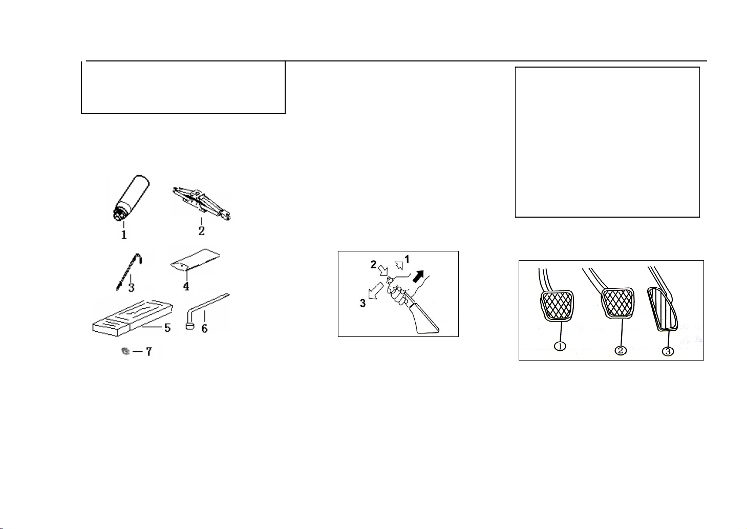
⑤ Triangle Warning Plate
⑥ Spanner for Tyre
○7 Clip
25. Too l Ki t
① Fire extinguisher
② Jack
③ Crank of Jack
④ Driver’s tool assembly
The tools shown ①②③④⑤⑥ in
the picture are one for each. Please
refer to Chapter 5 ‘Instruction for
using Jack’ to check the placement
of the jack and jack crank.
26. Brake Rod by hand
Draw up the brake rod, the vehicle
will stop; when release the stopping
brake, pull the brake rod a little up and
push the button on the top of the brake
rod with thumb and then put back the
brake rod in the normal position.
27. Pedal
Clutch Pedal
Clutch pedal can break transmission of
engine and wheel. Step down the
footboard, the engine power
disconnects, loose footboard, power
27
recover.
Note:
Do not put your foot on the clutch
pedal in the course of driving for
frequent use will cause the over
abrasion of the clutch.
Brake Pedal
It makes four wheels apply the brake
by steping on the brake pedal.
Environmental condition such as cold,
humidity, ice and snow etc. will cause
the brake shriek, it is normal, if the
brake screams in every brake or
shrieks loudly, please check the brake
system.
Ve hi c le De v ic es & O pe r at i on
Accelerator Pedal
The rotating speed is controlled by
accelerator pedal, step down the
accelerator pedal, the rotating speed of
the engine will increase and the output
power will go up.
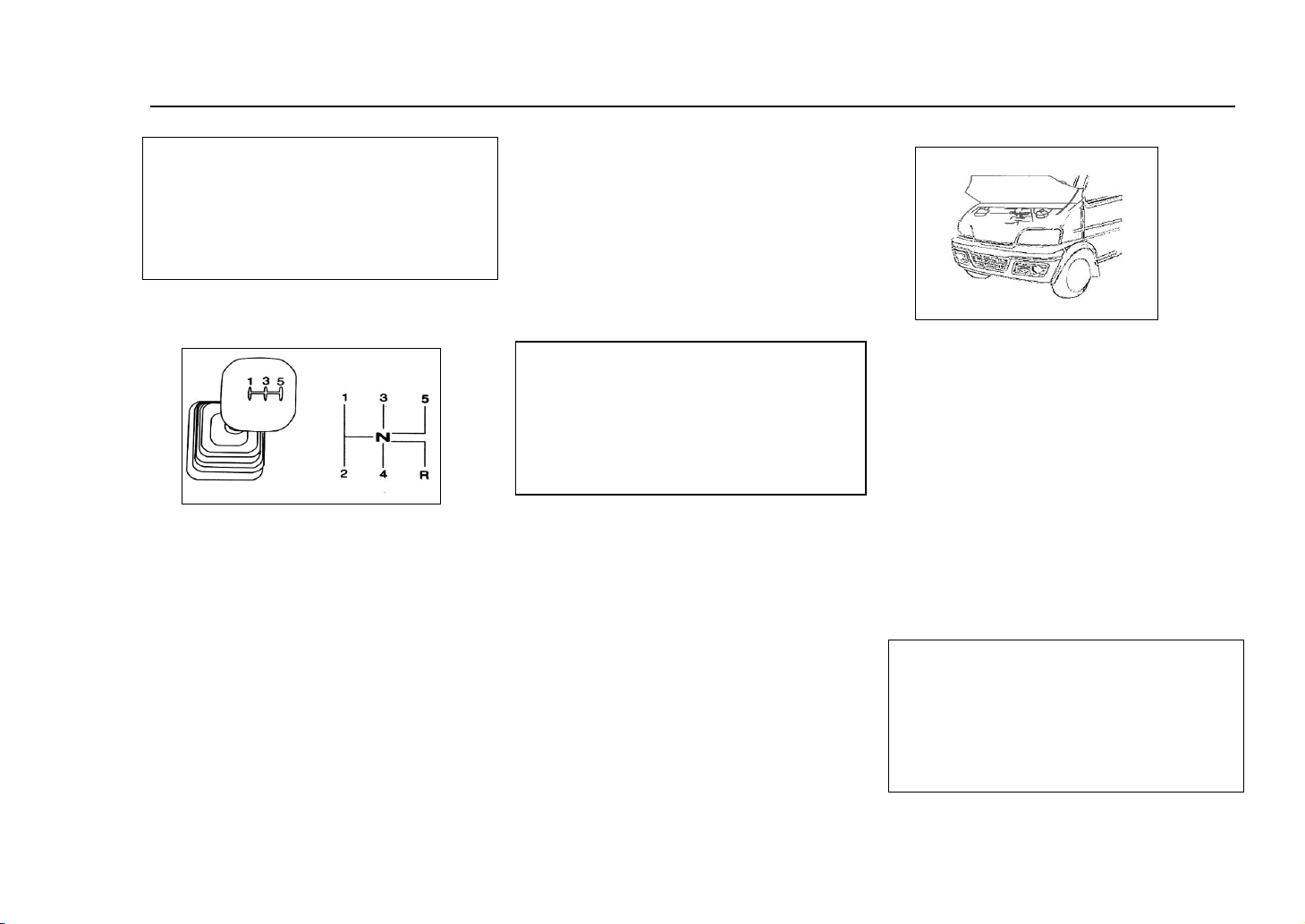
Shift Handlebar
Note:
Do not change the gearlever from 5th
gear into reverse gear. Please first
push the gearlever to neutral and then
change into reverse gear.
1st gear: first pull towards to left and
then push forward.
2nd gear: first pull towards to left and
then pull backward
3rd gear: push forwards in the central
position
4th gear: push backwards in the central
position
5th gear: pull towards right first and
then push backward
Reverse gear: pull towards left。
28. Hood
The handle of front storehouse lies
below left of the instrument board of
the driver's cabin. Before opening,
please pull the handle outwards and
then the handle up to open the front
cover, then prop up storehouse cover
with struts.
29. Light & Signal
Requirements
Note:
The user is allowed to external
lighting and signal device after
refitting.nor with mandatory standard
external lighting and signal device
28
 Loading...