

Tiger Tool 90150 Operating Instructions Manual
OPERATING INSTRUCTIONS
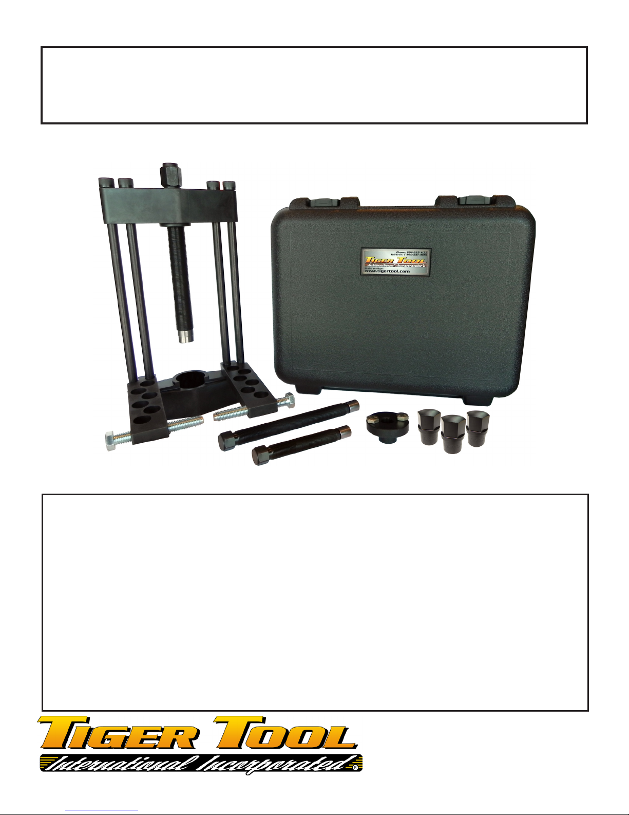
90150 MANUAL KING PIN PRESS
IMPORTANT: READ ALL INSTRUCTIONS BEFORE USING THIS PRODUCT
Safety Warning & Cautions:
When using this product;
1. KEEP WORK AREA CLEAN. Cluttered areas invite injuries;
2. ALWAYS SET PARKING BRAKE AND BLOCK TIRES;
3. USE EYE PROTECTION. Always wear approved impact safety glasses;
4. 10,000 psi LIMIT. Do not operate the hydraulic pump beyond the rated capacity;
5. STAY ALERT. Watch what you are doing. Use common sense! Do not operate this tool if you are unsure of
its application and use;
6. USE REPLACEMENT PARTS AND ACCESSORIES PROVIDED BY TIGER TOOL ONLY. All replacement
parts and accessories are available;
7. KEEP HYDRAULIC COUPLER PROTECTED WHEN NOT IN USE. Dust caps should be used on couplers
when not in use to avoid contaminants from entering the hydraulic cylinder and power source. is practice
will help to extend the life of this product and ensure continued consistent operation.
Call 1-800-661- 4661
for technical questions or
replacement parts.
OPERATING INSTRUCTIONS
90150 MANUAL KING PIN PRESS
ere are 3 forcing screws included with this kit:
1. e .875” diameter forcing screw and reducer are used on king pins 1.250” in diameter or smaller.
2. e 1.25” diameter forcing screw (6” length) is used on king pins 1.250” in diameter or larger where
there is limited space above the king pin. Once short forcing screw has run out of travel exchange for 12”
3. e 1.25” diameter forcing screw (12” length) is used on 1.250” diameter or larger.
Note: Both 1.25” diameter forcing screws share the same anvil.
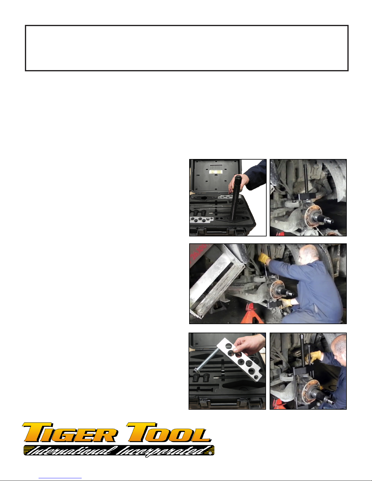
Step 1.
Select the corresponding forcing screw and thread it
into the screw plate. Rest the assembly on top of the
spindle aligning the forcing screw over the king pin.
Step 2.
Select the clearance plate and two 5/8” x 15” long
socket head cap screws. Align the center hole of the
clearance plate under the spindle to the screw plate
above. Install the two 5/8” x 15” long bolts in the
outer holes and thread them into the clearance plate.
Step 3.
Select the two 5/8” x 6” long tap bolts that are located
beneath the torque arms and thread them into the
torque arms as shown. Select the remaining two 5/8”
x 15” long socket head cap screws and install them
into the inner holes on the screw plate, torque arm,
and thread into the clearance plate.
Call 1-800-661- 4661
for technical questions or
replacement parts.
 Loading...