


Tiger Box Assembly Guide
Product Overview . . . . . . . . . . . . . . . . . . . . . . . . . . . . . . . . . 3
Tiger Box Features . . . . . . . . . . . . . . . . . . . . . . . . . . . . 3
Package Content . . . . . . . . . . . . . . . . . . . . . . . . . . . . . 4
Hardware Overview . . . . . . . . . . . . . . . . . . . . . . . . . . . 4
Site Installation . . . . . . . . . . . . . . . . . . . . . . . . . . . . . . . . . . . 6
Unpacking Tiger Box . . . . . . . . . . . . . . . . . . . . . . . . . . . 6
Installing Tiger Box . . . . . . . . . . . . . . . . . . . . . . . . . . . . 8
Installing the Drives . . . . . . . . . . . . . . . . . . . . . . . . . . . 9
Installing The Front Panel Bezel . . . . . . . . . . . . . . . . . . . 12
Connecting The Appliance to The Power . . . . . . . . . . . . . 13
Powering On The Appliance . . . . . . . . . . . . . . . . . . . . . . 15
Cabling Tiger Box . . . . . . . . . . . . . . . . . . . . . . . . . . . . . 15
Hardware Monitoring . . . . . . . . . . . . . . . . . . . . . . . . . . . . . . . 19
Monitoring the System Activity . . . . . . . . . . . . . . . . . . . . 19
Monitoring RAID Drives Activity . . . . . . . . . . . . . . . . . . . 20
Monitoring Client Connectivity . . . . . . . . . . . . . . . . . . . . 20
Monitoring Power Supply . . . . . . . . . . . . . . . . . . . . . . . . 21
Post Installation Maintenance . . . . . . . . . . . . . . . . . . . . . . . . . 21
Removing The Bezel and Cleaning the Filter . . . . . . . . . . . 21
Replacing a Failed Drive . . . . . . . . . . . . . . . . . . . . . . . . 23
Replacing a Failed Power Module . . . . . . . . . . . . . . . . . . 24

Tiger Box Assembly Guide
:
2
© Copyright 2016 Tiger Technology. All rights reserved.
TO THE EXTENT ALLOWED BY LOCAL LAW, NEITHER TIGER TECHNOLOGY
NOR ITS THIRD PARTY SUPPLIERS MAKE ANY OTHER WARRANTY OR
CONDITION OF ANY KIND, WHETHER EXPRESS OR IMPLIED, WITH RESPECT
TO THE TIGER TECHNOLOGY PRODUCTS, AND SPECIFICALLY DISCLAIM THE
IMPLIED WARRANTIES OR CONDITIONS OF MERCHANTABILITY,
SATISFACTORY QUALITY, AND FITNESS FOR A PARTICULAR PURPOSE.
Limitations of Liability
To the extent allowed by local law, the remedies provided in this Warranty Statement
are the customer's sole and exclusive remedies.
TO THE EXTENT ALLOWED BY LOCAL LAW, EXCEPT FOR THE OBLIGATIONS
SPECIFICALLY SET FORTH IN THIS WARRANTY STATEMENT, IN NO EVENT
SHALL TIGER TECHNOLOGY OR ITS THIRD PARTY SUPPLIERS BE LIABLE FOR
DIRECT, INDIRECT, SPECIAL, INCIDENTAL, OR CONSEQUENTIAL DAMAGES,
WHETHER BASED ON CONTRACT, TORT, OR ANY OTHER LEGAL THEORY AND
WHETHER ADVISED OF THE POSSIBILITY OF SUCH DAMAGES.
Local Law
This Warranty Statement gives the customer specific legal rights. The customer may
also have other rights that vary from state to state in the United States, from province
to province in Canada, and from country to country elsewhere in the world.
To the extent that this Warranty Statement is inconsistent with local law, this
Warranty Statement shall be deemed modified to be consistent with such local law.
Under such local law, certain disclaimers and limitations of this Warranty Statement
may not apply to the customer. For example, some states in the United States, as well
as some governments outside the United States (including provinces in Canada), may:
Preclude the disclaimers and limitations in this Warranty Statement from limiting the
statutory rights of a consumer (e.g.,the United Kingdom);
Otherwise restrict the ability of a manufacturer to enforce such disclaimers or
limitations; or Grant the customer additional warranty rights, specify the duration of
implied warranties which the manufacturer cannot disclaim, or not allow limitations
on the duration of implied warranties.
FOR CONSUMER TRANSACTIONS IN AUSTRALIA AND NEW ZEALAND, THE
TERMS IN THIS WARRANTY STATEMENT, EXCEPT TO THE EXTENT
LAWFULLY PERMITTED, DO NOT EXCLUDE, RESTRICT, OR MODIFY, AND ARE
IN ADDITION TO, THE MANDATORY STATUTORY RIGHTS APPLICABLE TO
THE SALE OF TIGER TECHNOLOGY PRODUCTS TO SUCH CUSTOMERS.
Tiger Technology reserves the right to revise and improve its products as it sees fit.
This publication describes the state of this product at the time of its publication, and
may not reflect the product at all times in the future.
THIRD-PARTY TRADEMARKS
All other brand names, product names, or trademarks belong to their respective
holders.
Manual Revision and Control
Title: Tiger Box Assembly Guide
Hardware model: 2.0
Date: December 16, 2016
Revision Record
Date Description Version
01/23/2013 Initial Draft 1.0
01/24/2013 Replacing a failed drive steps updated. 1.0
08/01/2013 2 x SAS ports for directly connecting Tiger Box expansion
chassis added.
2.0
08/01/2013 Power and reset buttons added at the back of the
appliance.
2.0

Tiger Box Assembly Guide
Product Overview: Product Overview
3
Congratulations on your purchase of Tiger Box, Tiger Technology’s all-in-one shared
storage appliance. This manual describes how to install and connect Tiger Box at your
site - from unpacking the appliance to powering on the system.
Before proceeding, make sure that you have read carefully all instructions, paying
special attention to the following symbols used in this guide:
SAFETY WARNING
IMPORTANT NOTE
TIP
You can find the most up-to-date version of this manual at the following address:
http://www.tiger-technology.com/products/tiger-series/tiger-box/docs
Product Overview
Tiger Box is a state of the art, high performance shared storage system that offers the
simplicity of NAS and the performance characteristics of a true SAN. The compact
rack-mountable 3U appliance combines a metadata controller and highly optimized
RAID 5 storage, comprised of 16 enterprise-class drives (drive capacity depends on
specific configuration), which can be accessed by client computers via 8/16Gb Fibre
Channel, 10Gb Ethernet and/or 1Gb Ethernet.
The appliance is shipped fully configured to you. To deploy Tiger Box you should
simply:
1.
Rack-mount the appliance or install it on a table top (see “Installing Tiger Box” on
page 8).
2.
Install the drive carriers in the enclosure (see “Installing the Drives” on page 9).
3.
Connect the appliance to the power source and turn it on (see “Connecting The
Appliance to The Power” on page 13).
4.
Connect client computers to the ports of the appliance - 8/16Gb FC, 10GbE and/or
1GbE, depending on the model (see “Cabling Tiger Box” on page 15).
Tiger Box Features
•
3U, 19” rack-mount chassis with excellent anti-vibration mechanical design and
thermal solution.
•
RAID 5 shared storage comprised of 16 hot-swappable drives (a failed RAID drive
can be replaced while the system is operating and no data on the volume will be lost).
•
8/16Gb Fibre Channel, 10GbE and/or 1GbE ports for connecting client computers.
•
Redundant power supply (a failed power module can be replaced while the system
is operating).
•
4 x 80mm system cooling fan modules.
•
2 x internal 2.5” system drives (RAID 1).
•
2 x SAS ports for directly connecting Tiger Box expansion chassis
•
Tiger Technology software for shared storage management and diagnostics.
•
projectStore software for advanced project collaboration.
Tiger Box Asse mbly Guide
Product Overview: Package Content
4
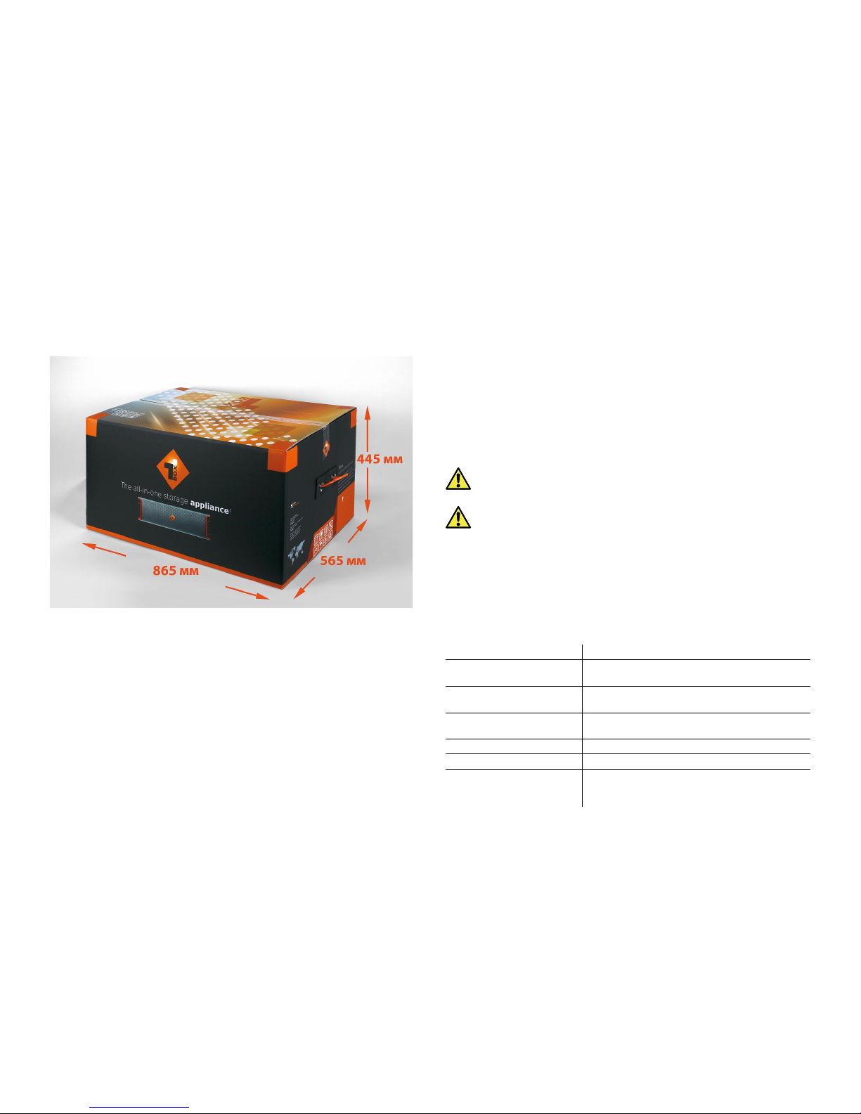
Package Content
The package you have received weighs 47 kg and has the following dimensions:
It must contain the following:
•
1 x 3U, 19" rack-mount chassis.
•
16 x 3.5" disks each installed in a hot-swappable drive carrier.
• (optional
) 1 x 3.5" spare disk installed in a hot-swappable drive carrier for online
recovery of a failed RAID disk.
•
1 x square-hole rack-mount rails kit:
•
2 x slide rails.
•
6 x screws for attaching the rails to the appliance.
•
4 x screws for attaching the rails and the appliance to the rack.
•
printed instructions for installing the rails.
•
2 x power cables.
•
1 x 1.80m UTP network cable.
•
1 x front panel bezel.
•
1 x system restore USB flash drive.
•
1 x CD with instructions.
•
1 x Tiger Box reset tool (used for pressing the shut down and reset buttons at the
front of the appliance).
Note:
It is advisable to use the power and reset buttons at the back of the
appliance (see “Powering On The Appliance” on page 15).
Important:
If any of the components listed above is missing from your
shipment, please contact your reseller or Tiger Technology support
immediately.
Important:
Check if both warranty stickers at the back of the chassis are
intact. If a warranty sticker is damaged, immediately contact Tiger
Technology at support@tiger.technology.com
Hardware Overview
Note:
The pictures used to illustrate the product in this manual may differ from the
Tiger Box appliance you have received depending on the model and firmware version.
Technical Characteristics
Description Specification
Chassis dimensions 25.5" (D) x 17.2" (W) x 5.2" (H)
647.7 mm (D) x 437 mm (W) x 132 mm (H)
Net weight
(without drives installed)
approx. 26kg/58lbs
Gross weight
(with RAID drives installed)
approx. 40kg/88lbs
Power Consumption Max 720 Watts
Power Consumption Idle 350 Watts
Power Supply Unit High-efficiency 720w (1+1) Redundant Hot
Swappable Power Supply W/ PFC, AC 100 ~
240V Full Range, 50Hz ~ 60Hz

Tiger Box Assembly Guide
Product Overview: Hardware Overview
5
Front View
Apart from the 16 drive bays for the drives comprising the shared storage, Tiger Box's
front panel features the following elements:
•
LED indicators for monitoring system activity (see “Monitoring the System Activity”
on page 19).
•
Buttons:
Note:
To prevent you from accidentally shutting down/restarting the appliance,
you can press the System power button and System reset button only using the
Tiger Box reset tool or a similar tool.
•
USB 2.0 port - for firmware updates and system recovery
Rear View
The back of the appliance features the following elements:
•
2 x power supply modules.
•
System power button and system reset button.
Temperature Range Operating: 10ºC ~ 20ºC (50ºF~77ºF)
Non-operating: -40
º
C ~ 70ºC (-40ºF~158ºF)
Humidity Range 20% ~ 60% non-condensing
Description Specification
alarm mute button
- mutes the alarm in case of power
supply failure or fan failure.
Note:
Pressing the alarm mute button only silences the alarm. The
alarm light stays on until the problem is resolved.
system reset button
system power button

Tiger Box Assembly Guide
Site Installation: Site Installation
6
•
2 x SAS ports for directly connecting Tiger Box expansion chassis.
•
depending on the configuration you have purchased client connectivity through:
•
8/16Gb FC ports;
•
10Gb Ethernet ports;
•
1Gb Ethernet ports;
•
1 x Ethernet port for safety net access to the appliance.
•
1 x Ethernet port for public and Internet communication.
Tiger Box supports the following types of cables for connection of client computers
and/or switches:
Clients via Fibre Channel —
fibre optic cable with LC connectors for SFP+
transceivers.
Clients via 10GbE —
depending on the 10GbE adapter model:
•
fibre optic cable with LC connectors for SFP+ transceiver or copper cable with SFP+
transceiver
•
patch cable with RJ-45 modular connectors
Clients via 1GbE —
patch cable with RJ-45 modular connectors.
Site Installation
Unpacking Tiger Box
Important:
Do not throw away any of the packaging components, until you
ensure that the appliance works properly and there is no need to return any
part.
Tip:
It is advisable to keep all packaging components until the warranty of
your appliance expires.
1.
Cut the straps of the box, cut or remove the tape and open the flaps.
2.
Take out the rack-mount rails kit and then the top foam cover.

Tiger Box Assembly Guide
Site Installation: Unpacking Tiger Box
7
3.
Take out the foam case with the front panel bezel.
4.
Take out the foam case with the spare RAID drive (if your order includes one), the
Tiger Box System Restore USB Flash Drive and the instructions CD.

Tiger Box Asse mbly Guide
Site Installation: Installing Tiger Box
8
5.
Take out the foam case with the sixteen RAID drives.
6.
Take out the two power cables and the network cable.
7.
Take out the two foam protectors and take the appliance out of the box and place it
on a surface, ensuring that the system remains stable.
Important:
Tiger Box weighs approximately 26.5kg. Attempting to move it
without assistance could cause personal injury. Request assistance and use
proper lifting techniques when lifting the appliance.
Installing Tiger Box
Before installing Tiger Box in a rack or on a table top, consider the limitations for
maximum cable lengths, when deciding on the location of the appliance within your
facility. Also check the appliance's technical characteristics to make sure that the
rack/the table meets the physical, electrical, and thermal specifications.

Tiger Box Assembly Guide
Site Installation: Installing the Drives
9
Rack-mounting Tiger Box
You can mount Tiger Box in a standard, 19-inch-wide, four-post rack.
A square-hole rack-mount rails kit is included in your shipping. If you are installing
Tiger Box in a rack, follow the instructions supplied in the rack-mount rails kit to
install the appliance.
Tip:
Install the heaviest devices in the lowest position in the rack. To make the
lift of Tiger Box easier, insert the RAID drive carriers after installing the
appliance in the rack.
Installing Tiger Box on a Table Top
If you do not plan to install your Tiger Box in a rack, and you opt for tabletop
installation, ensure that:
•
the surface is clean and in a safe location;
•
the appliance is stable, its bottom faces down and its top faces up.
Tip:
To determine the top and bottom of the appliance, use the text direction on the
printed labels.
•
the appliance is installed off the floor to avoid drawing dust accumulated on the
floor into the interior of the appliance by the cooling fans.
Important:
Excessive dust inside the appliance can cause overheating and
component failures.
•
there must be at least 50cm (19 inches) of clearance at the front and rear of the
appliance for installing and replacing the RAID drives, or accessing network cables or
equipment;
•
the appliance receives adequate ventilation (it is not being installed in an enclosed
cabinet where ventilation is inadequate);
•
the appliance is not in close proximity to devices that emit strong electromagnetic
waves;
Installing the Drives
Tiger Box is shipped to you with a pre-configured RAID 5 storage, comprised of 16
disks. Each disk is installed in a hot-swappable drive carrier. You can replace a failed
hard disk, while Tiger Box is operating and no data on the storage will be lost (see
“Replacing a Failed Drive” on page 23). For safety reasons, the drives in the carriers
are shipped separately and you should install them yourself in the appliance.
Important:
To prevent drive failure, in case the drives have been
transported to you in cold environment (temperature less than 15°C/59°F),
let the drives return to room temperature for at least 3 hours, before
installing them in the enclosure.
Each drive is labeled and must be inserted in the drive bay corresponding to its
number as described in this scheme:
Tip:
If you intend to rackmount the appliance, to make the lift easier, insert
the drive carriers after installing the appliance in the rack.
Warning:
Before proceeding, make sure that the power cord is disconnected
from the power source!
Important:
To prevent electrostatic discharge (ESD), touch grounded metal
before touching any of the appliance components. You can also prevent ESD

Tiger Box Assembly Guide
Site Installation: Installing the Drives
10
when inserting the drive carrier into the enclosure, by holding the appliance enclosure
with the other hand.
To install the drives:
1.
Take out a drive carrier from its antistatic bag.
Important:
Handle the hard drive by the sides only, making sure you don't
touch the printed circuit board or the connectors.
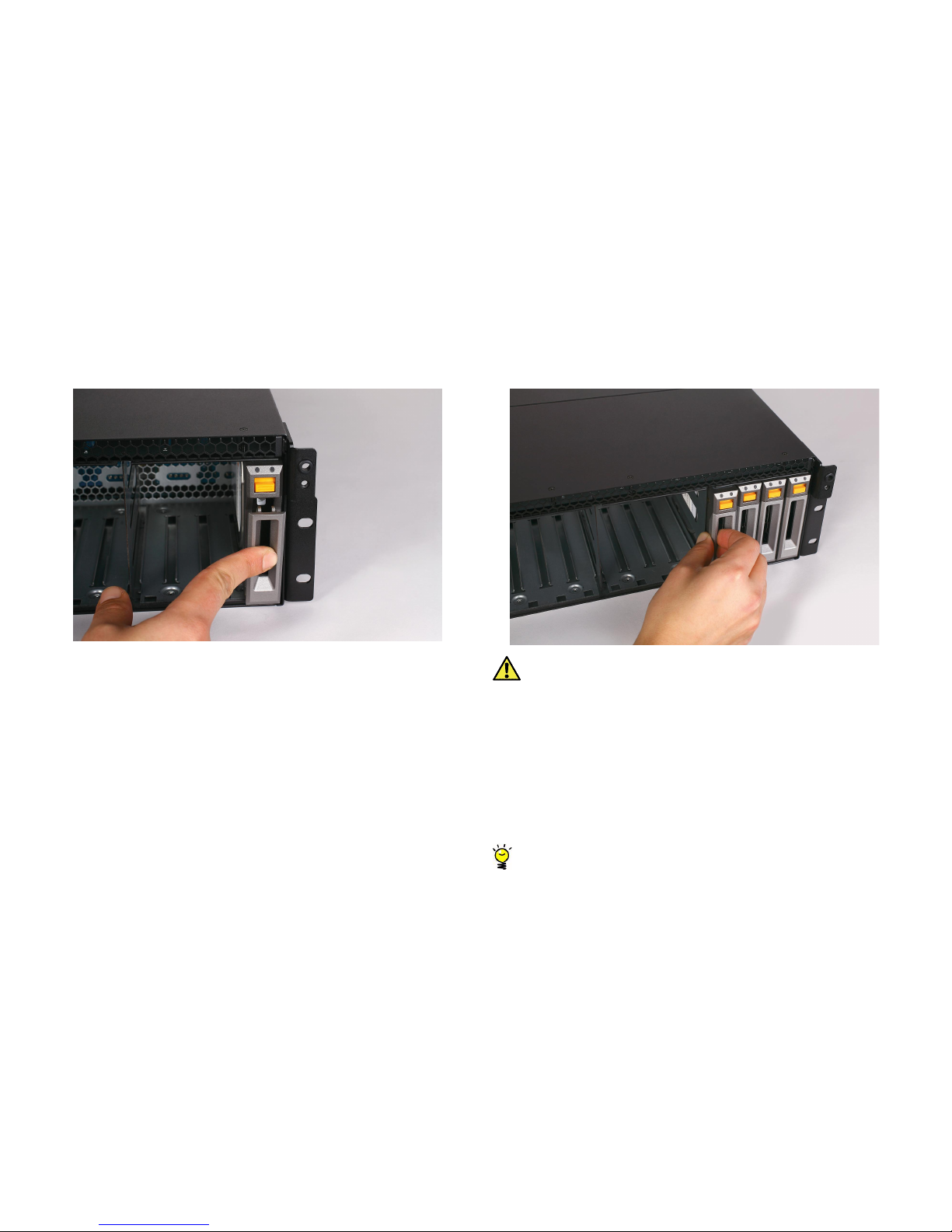
2.
Press upwards the lever release button on the front of the drive carrier.
The lever opens.

Tiger Box Assembly Guide
Site Installation: Installing the Drives
11
3.
Find the label on the drive that specifies its corresponding drive bay.
4.
Slide the drive carrier into the corresponding slot until the lever makes contact
with the enclosure.
Tige r Box As sembly Guide
Site Installation: Installing The Front Panel Bezel
12
5.
Push the lever up to finish sliding the drive carrier into the drive bay. To ensure that
the lever is locked, you must hear a clicking sound.
6.
To check that the drive carrier is properly installed and makes full contact with the
drive bay, try to pull it out without unlocking the lever.
Important:
If the drive can be pulled out, repeat the steps for installing it from
the beginning.
7.
Repeat the above steps for each drive in the kit.
Installing The Front Panel Bezel
Tiger Box is shipped with a bezel that should cover the front panel. The bezel features
an advanced protection filter that prevents dust from accumulating in the RAID drives
and the enclosure.It is advisable to clean the bezel filter every 3 months. For steps
about removing and cleaning the bezel, refer to “Removing The Bezel and Cleaning the
Filter” on page 21.
Tip:
You can install/remove the bezel at any time without having to turn off
or dismount the appliance from the rack.
Tig er Box Asse mbly G uide
Site Installation: Connecting The Appliance to The Power
13
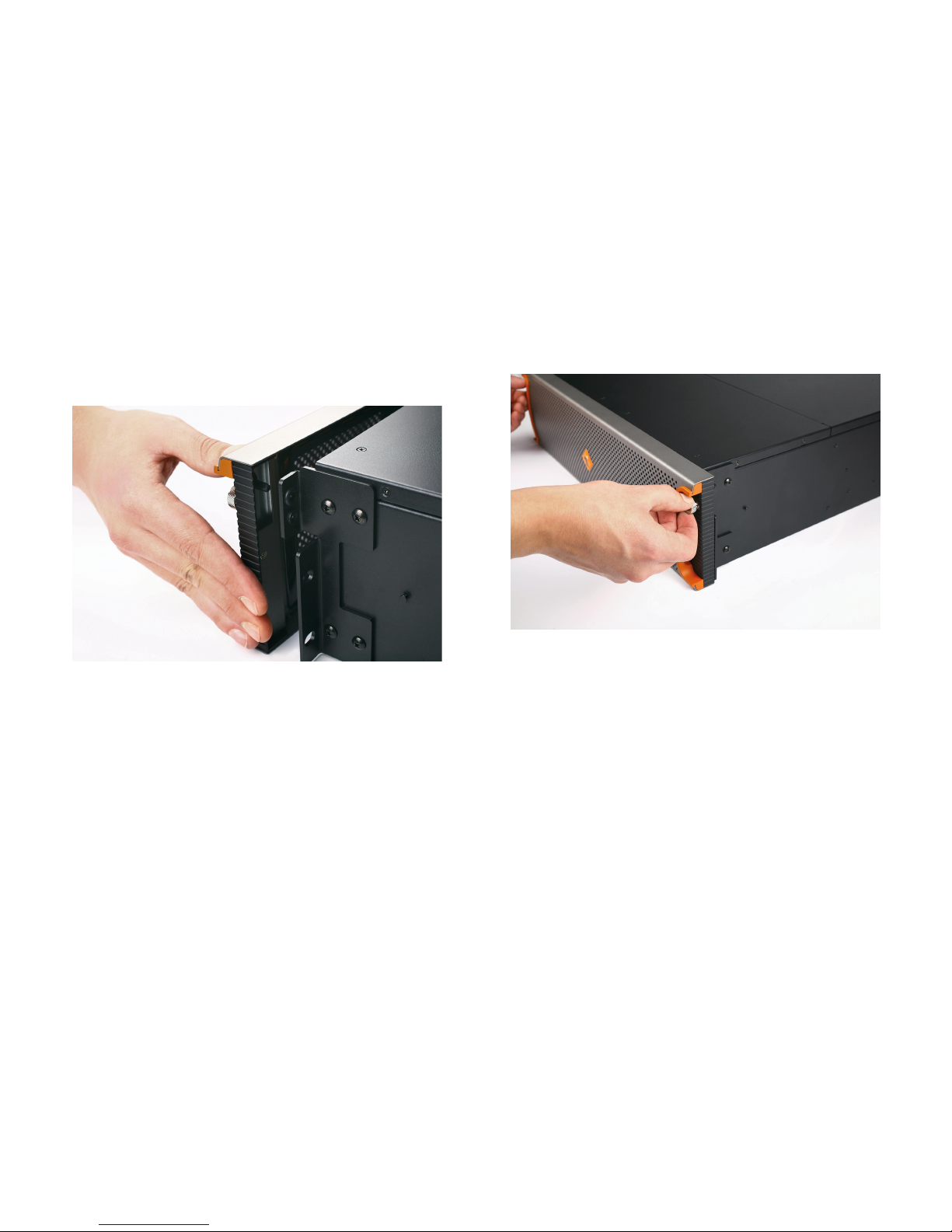
To install the bezel:
1.
Insert the tabs on each end of the bezel into the flanges on each side of the
appliance's front panel.
2.
Screw the two thumb screws on either side clockwise.
Connecting The Appliance to The Power
Your Tiger Box is shipped to you with two power supply modules, installed in the rear
of the appliance. These modules supply redundant power to Tiger Box - should a
power supply module fail, you can replace it while the system is operating (see
“Replacing a Failed Power Module” on page 24). You can replace a failed power
module only with a power module of the same model.

Tig er Box Asse mbly G uide
Site Installation: Connecting The Appliance to The Power
14
To connect the appliance to the power supply:
1.
Plug the power cord in the power socket of the power supply module.
2.
Connect the power cord to the power outlet.
If the appliance is properly connected, the power module LED indicator will start
blinking in green. If there's problem with the module installation, its LED indicator
is red (blinking or solid) or there is no light at all.

Tiger Box Assembly Gui de
Site Installation: Powering On The Appliance
15
Powering On The Appliance
To power on the appliance:
1.
Press once the power button
2.
Wait until the power status LED at the front becomes solid green.
To power off the appliance:
Important:
It is advisable to always attempt to shut down the appliance
through the web UI, before resorting to hard shut down.
Press continuously the power button at the back of the appliance, until its light
goes off.
To restart the appliance:
Important:
It is advisable to always attempt to restart the appliance through
the web UI, before resorting to forced restart of the system.
Press the Reset button at the back of the appliance.
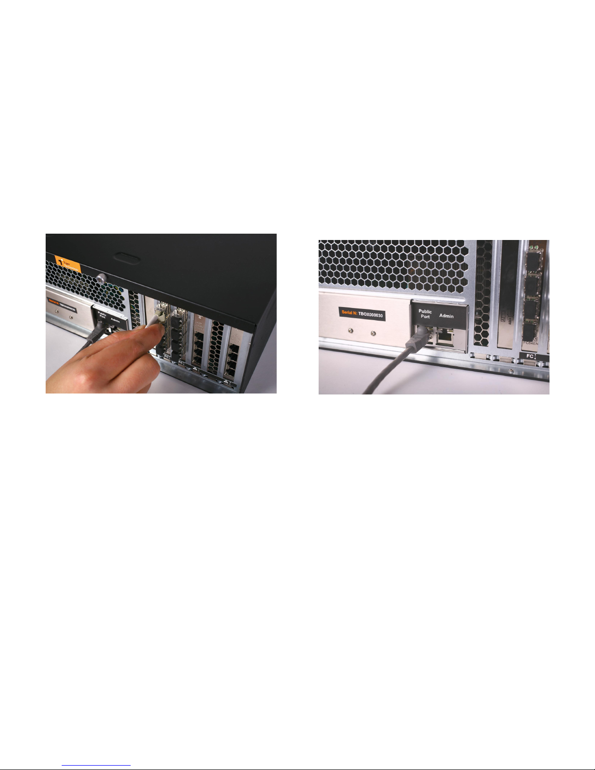
Cabling Tiger Box
Tiger Box features a Public network port for connection to a computer, from which to
perform the initial setup of Tiger Box and assign IP addresses to all available network
ports (refer to Administering Tiger Box User's Guide). Before cabling Tiger Box it is
important to carefully plan the topology of your network. Client computers can
connect to Tiger Box as SAN clients (connected via Fibre Channel) or LAN clients
(connected via 1GbE or 10GbE). While SAN clients need the additional network
connection (through a 1GbE/10GbE port) for metadata exchange with Tiger Box, LAN
clients use only one network port for both data traffic and metadata exchange. As
metadata overhead is kept to an absolute minimum, there's no need to connect each
SAN client to a separate network port, but rather connect them to the Public port
through an Ethernet switch and spare the remaining network ports for connecting
LAN clients. You can connect client computers directly to the available FC/10GbE/
1GbE ports for full bandwidth, or you can expand the number of connected clients by
deploying FC/Ethernet switches. Note that in this configuration the bandwidth
available to each node decreases, as additional nodes are added.
Important:
If you want to connect your Fibre Channel clients using multipathing, prior
to connecting them to the appliance, contact Tiger Technology support for
instructions.
Tiger Box also allows you to team the ports of a single 1/10GbE NIC (the Ethernet
switch or the client computer NIC must support link aggregation). Besides allowing a
network card to be accessed through a single IP address, and sparing you the need to
specify a separate IP address for each port, port teaming also can provide more
bandwidth through a single IP address.
Important:
It is advisable when planning the topology of the network, to
make sure that no client computer has more than one network connection
(through two or more IP addresses) to the appliance - for example, direct
connection through a 10GbE port and connection through an Ethernet switch.
Additionally, Tiger Box features an Admin network port, which is assigned a preset IP
address, which you cannot change. The Admin port is designed as a safety net,
providing you with access to web interface in case you misconfigure the appliance’s
network identification and fail to connect to it.
Tiger Box Assembly Guide
Site Installation: Cabling Tiger Box
16
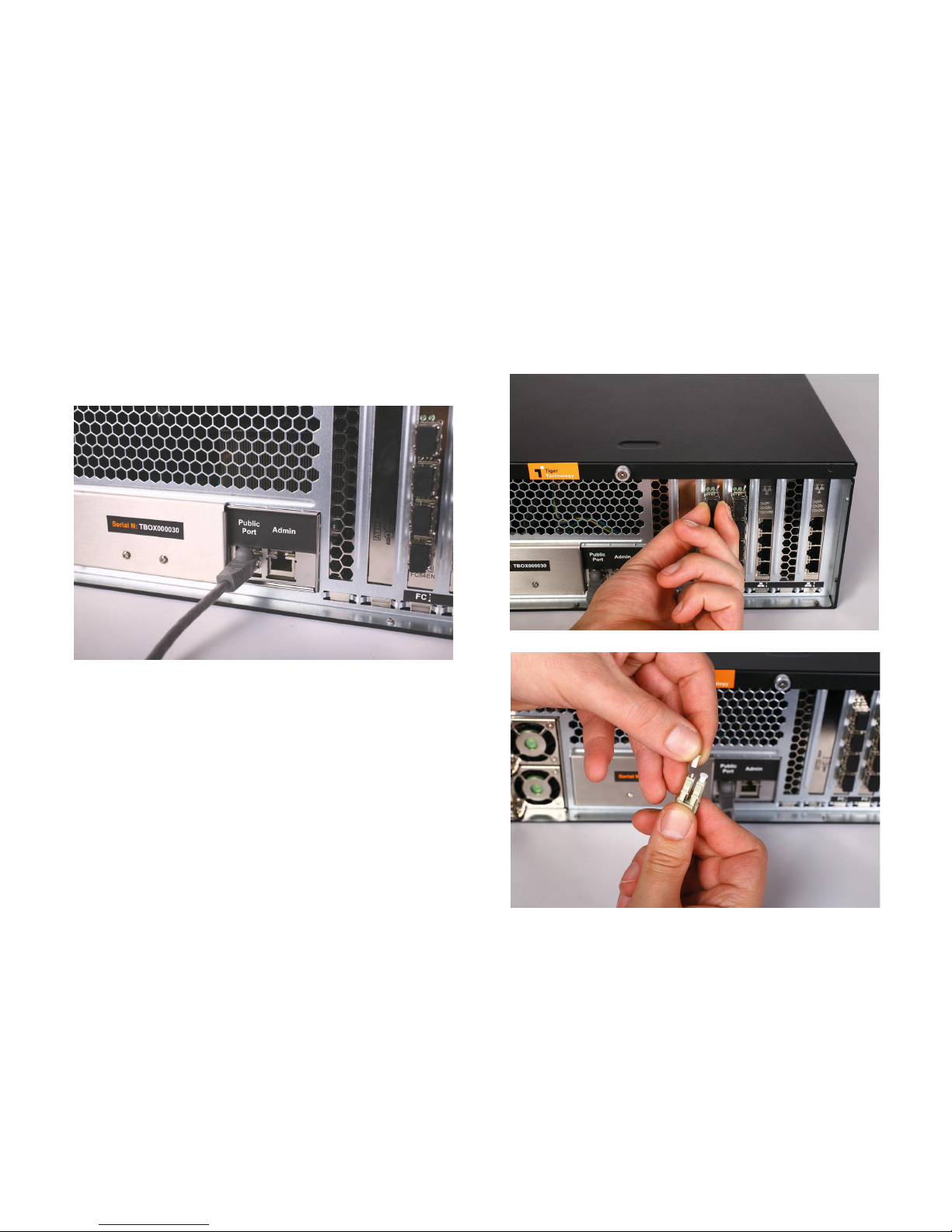
To connect a computer to the Public port:
1.
Plug one end of the network cable provided in the shipment in the port with label
Public port.
2.
Plug other end of the network cable in the LAN port of the computer, from which
you want to perform the initial setup.
Note:
If you intend to provide SAN computers with network communication to the
appliance through the Public port, once you perform the initial setup, you can
disconnect the computer, from which you have performed the setup, and connect
the Public port to an Ethernet switch, to which to connect all SAN computers.
For details about performing the initial setup of Tiger Box, refer to Tiger Box
Administration Guide.
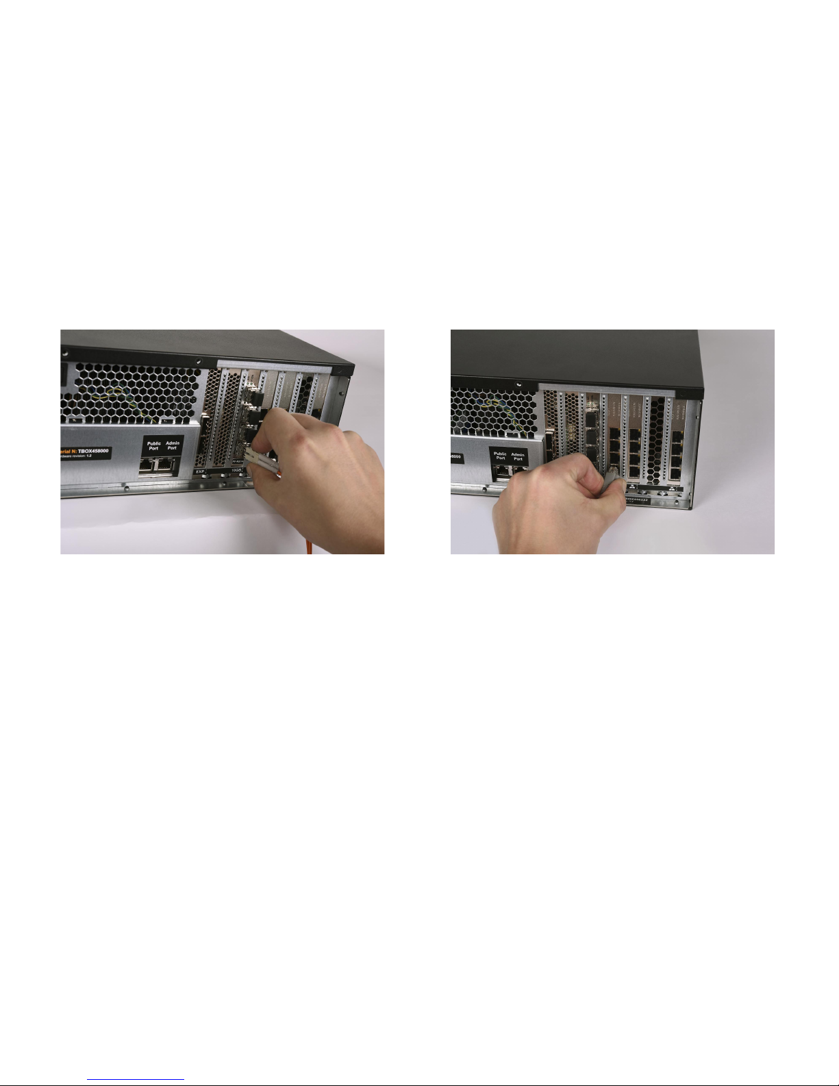
To connect a SAN computer:
Note:
Your Tiger Box shipment doesn't include fibre optic and copper Fibre Channel
cables. The FC ports are with optical SFPs.
1.
Remove the protective black cap from the Fibre Channel port.
2.
If your fibre optic cable has protective caps, remove them.
Tiger Box Assembly Guide
Site Installation: Cabling Tiger Box
17
3.
Plug one end of the fibre optic cable into the SFP socket of the appliance port.
4.
Do one of the following:
•
Plug other end of the fibre optic cable in the port of the Fibre Channel card of the
client computer.
•
Plug other end of the fibre optic cable in the port of the Fibre Channel switch and
then connect the switch to the client computer's FC port.
Note:
If you opt for interconnection via switch, refer to your switch documentation
for further setup instructions.
5.
Plug one end of the network cable into one of the available network ports of the
appliance.
Note:
As metadata overhead is kept to an absolute minimum, there's no need to
connect each SAN client to a separate network port, but rather connect them to
the Public port through an Ethernet switch and spare the remaining network ports
for connecting LAN clients.
6.
Do one of the following:
•
Plug other end of the network cable in the port of the network card of the client
computer.
•
Plug other end of the network cable in the port of the Ethernet switch and then
connect the switch to the client computer's network port.
Note:
If you opt for interconnection via switch, refer to your switch documentation
for further setup instructions.
To connect a LAN computer via 10GbE port:
Note:
Your Tiger Box shipment doesn't include copper and fibre optic cables.
Tiger Box Assembly Guide
Site Installation: Cabling Tiger Box
18
1.
Plug one end of the cable into the 10GbE port of the appliance.
2.
Do one of the following:
•
Plug other end of the cable in the 10GbE port of the client computer.
•
Plug other end of the cable in the 10GbE port of the Ethernet switch and then
connect the switch to the client computer's 10GbE port.
Note:
If you opt for interconnection via switch, refer to your switch documentation
for further setup instructions.
To connect a LAN computer via 1GbE port:
Note:
Your Tiger Box shipment doesn't include twisted pair cables.
1.
Plug one end of the cable into the network port of the appliance.
2.
Do one of the following:
•
Plug other end of the cable in the network port of the client computer.
•
Plug other end of the cable in the port of the Ethernet switch and then connect
the switch to the client computer's network port.
Note:
If you opt for interconnection via switch, refer to your switch documentation
for further setup instructions.

Tiger Box Assembly Gui de
Hardware Monitoring: Hardware Monitoring
19
To connect a computer to the Admin port:
1.
Plug one end of the network cable provided in the shipment in the port with label
Admin port.
2.
Plug other end of the network cable in the LAN port of the computer, from which
you want to access the web interface.
Important:
The Admin port is designed solely as a safety net, allowing you to
access the web interface, when you have misconfigured the appliance’s network
identification and fail to access it from any computer.
Hardware Monitoring
Monitoring the System Activity
The LEDs on the front panel of Tiger Box allow you to monitor the system activity. You
can monitor the system activity without removing the front panel bezel:
Indicator LED color Status Description
power status LED
green blinking
stand by
(power is on, but the
system is not turned
on)
solid power on
red solid power supply error
or no power
system activity LED 1 green solid system is idle
green slow blinking
(once a second)
maintenance
operations running
while system is idle
(like disk
defragmentation,
for example)
green fast blinking
(more than 4
times a second)
system is busy
Tiger Box Assem bly Gu ide
Hardware Monitoring: Monitoring RAID Drives Activity
20
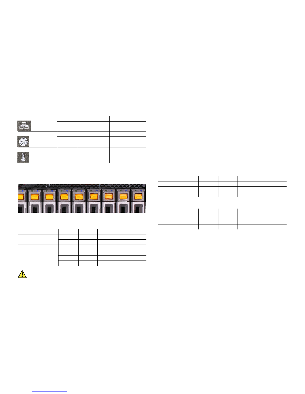
Monitoring RAID Drives Activity
You can monitor the activity of the RAID drives using the LED indicators on the top
of each HDD carrier:
Note:
To monitor RAID drives activity, you should remove the front panel bezel.
Important:
To diagnose RAID drive failure it is advisable to regularly check
the RAID status in the Storage page of Tiger Box’s web UI (see Tiger Box
Administration Guide). Degraded RAID status indicates that a drive has failed
and needs to be replaced with the spare drive, following the steps described in
“Replacing a Failed Drive” on page 23.
Monitoring Client Connectivity
You can monitor the connectivity of SAN/LAN clients using the LED indicators on the
FC/10GbE/1GbE ports respectively.
FC ports
Your configuration can include 8Gb or 16Gb FC cards. The FC cards are set up to work
in auto mode i.e. their ports transmit data depending on the connectivity mode of the
client’s (or the switch’s) FC card. You can view the transmission mode through any FC
port using the LED indicators above it. If the FC port LED’s light is off the port is
inactive.
8Gb Cards
16Gb Cards
network activity LED 2 amber blinking online
- - offline or no
transaction
fan failure LED red blinking error or fan failure
-- OK
overheat LED red blinking system overheating
-- OK
Indicator LED color Status Description
HDD power
(right indicator)
blue solid HDD power on
- - HDD power off
HDD status
(left indicator)
green blinking data I/O activity
green solid (SAS disks) idle state
red solid HDD failure or error
- - (SATA disks) idle state
Indicator LED color Status Description
left green solid 2Gb mode
right green solid 4Gb mode
both green solid 8Gb mode
Indicator LED color Status Description
left green solid 4Gb mode
right green solid 8Gb mode
both green solid 16Gb mode

Tig er Box Asse mbly G uide
Post Installation Maintenance: Monitoring Power Supply
21
10 GbE Ports
You can view the status of your connection through a 10GbE port using the LED
indicator above it.
1 GbE Ports
You can view the status of your connection through an 1 GbE port using the LED
indicators above it.
Monitoring Power Supply
You can monitor the activity of the power modules using their LED indicator:
Post Installation Maintenance
Removing The Bezel and Cleaning the Filter
You should remove the front panel bezel to mute the alarm in case of power supply
failure or fan failure, and also when replacing a failed RAID drive. You can remove and
install the bezel at any time without having to turn off or dismount the appliance from
the rack.
The bezel features an advanced protection filter that prevents dust from accumulating
in the RAID drives and the enclosure. It is advisable to clean the bezel filter every 3
months.
Indicator LED color Status Description
activity LED
(left indicator)
green blinking The adapter is sending or
receiving network data at
up to 10Gbps.
- - No network activity on the
link.
link LED
(right indicator)
amber solid or
blinking
The 10GbE LAN card is
initialized.
--The adapter is not
receiving power or the
10GbE LAN card is not
initialized.
Indicator LED color Status Description
speed LED
(left indicator)
amber solid Operating as a Gigabit
connection (1000 Mbps).
green solid Operating as a 100-Mbps
connection.
- - Operating as a 10-Mbps
connection.
link LED
(right indicator)
green blinking There is activity on this
port.
- - No link is established.
Indicator LED color Status Description
power module green blinking system is in stand by mode
solid system is in normal mode
red blinking no power
solid power module failure

Tiger Box Assembly Guide
Post Installation Maintenance:
22
To remove the bezel:
1.
Loosen the thumb screws on either side of the bezel.
2.
Gently pull away the bezel from the front panel of the appliance.
To clean the bezel filter:
1.
Remove the bezel (see steps on page 22).
The filter is snapped on the inside frame of the bezel.

Tig er Box Asse mbly G uide
Post Installation Maintenance: Replacing a Failed Drive
23
2.
Take the filter off by hand and wash it under running water, then leave it to dry.
3.
When the filter is completely dry, fit it inside the bezel by snapping its magnetic
strips to the inside frame of the bezel.
4.
Install the bezel (see steps on page 13).
Replacing a Failed Drive
You can replace a failed hard disk, while Tiger Box is operating and no data on the
storage will be lost. If your order includes a spare drive, it is shipped to you preinstalled in a drive carrier and is ready to replace the one that has failed.
You can also replace a failed drive with a drive not included in your shipment. In this
case the new drive must be exactly the same size and make as the one that has failed.
Additionally, you should uninstall the failed drive from its drive carrier and then
install the replacement drive in the carrier.
Important:
Periodically check the RAID status in the Storage page of Tiger
Box’s web UI. Degraded RAID status indicates that a drive has failed and
needs to be replaced. If more than one RAID drive fails, the RAID will become
inaccessible and data loss is possible.

Ti ger B ox A sse mbly Gui de
Post Installation Maintenance: Replacing a Failed Power Module
24
To replace a failed RAID disk with the spare drive:
1.
Remove the front panel bezel.
2.
Find the failed drive - its HDD status LED indicator (the left indicator) is red.
3.
Press the lever button on the front of the drive carrier to release the lever and gently
pull out the drive carrier.
Important:
If by accident you pull out other than the failed drive, the RAID
becomes offline. Insert back the healthy drive and wait until the RAID is again
online. After that find the failed drive and proceed with the steps.
4.
(
if your order doesn’t include a spare drive
) Uninstall the failed drive from its
drive carrier and then install the replacement drive in the carrier.
5.
Insert the drive carrier with the spare disk into the drive bay, following the steps on
page 10.
When the HDD status LED of the drive stops blinking, rebuild the RAID, following
the steps described in the Tiger Box Administration Guide.
Important:
Make sure you order an additional spare drive in case another
RAID drive fails in the future.
Replacing a Failed Power Module
Your Tiger Box is shipped to you with two power supply modules, installed in the rear
of the appliance. These modules supply redundant power to Tiger Box - should a
power supply module fail, you can replace it while the system is operating. You can
replace a failed power module only with a power module of the same model.
To replace a failed power module:
1.
Find the failed power module (the light of its LED indicator is solid red).

Ti ger B ox A sse mbly Gui de
Post Installation Maintenance: Replacing a Failed Power Module
25
2.
Unplug its power cable from the module's socket.
3.
With the finger of one hand push the side tab of the power module to the right.
4.
While pressing the tab, pull the lever at a 90° angle and slide out the unit from the
appliance.

Ti ger B ox A sse mbly Gui de
Post Installation Maintenance: Replacing a Failed Power Module
26
5.
Slide in the new power module and hear the side tab click into the bay.
6.
Push back the lever of the power module to lock it.
7.
Plug the power cable in the module's socket and power on the appliance.
 Loading...