

Page 1
2017 TigerStop, LLC
TigerStop
®
February 2017 Mk1
Register warranty and enable TigerStop
Optimizer BEFORE installation!
See Page 14!
1
Page 2
Serial Number
Safety First!
WARNING: Installation of your TigerStop Product must be done by a person trained in the safe
design and installation of automation products, and in the safe operation of power equipment. Ensure
that such installation meets all legally required safety requirements and guidelines, and that proper
guarding and safety devices are provided on all sides of the equipment to preclude unintended access
during operation. Consult with and follow the recommendations of a qualifi ed safety engineer.
WARNING: TigerStop Products are components intended for use in conjunction with potentially
dangerous machinery. The use of TigerStop Products does not make other machinery safe. TigerStop
Products are not intended to substitute, in any manner, for safe operating practices in general, or for
safety features present in other machines designed to make those machines as safe as possible.
TIGERSTOP PRODUCTS, IF USED OR INSTALLED IMPROPERLY, MAY CAUSE PERSONAL
INJURY OR DEATH AND SHOULD ONLY BE OPERATED BY PERSONS TRAINED IN THEIR
SAFE OPERATING PROCEDURES. Illustrations of TigerStop Products in use do not show, and are
not intended to show, all safety features and practices necessary for their safe operation.
GENERAL
WARNINGS
IMPORTANT SAFETY INFORMATION. READ ALL WARNINGS BEFORE OPERATING THIS PRODUCT.
WARNING: TigerStop Products must be installed in accordance with all local, state, and federal
regulations. Only personnel properly trained in the safe design and installation of automation
machinery and related power equipment should install TigerStop Products onto other equipment, to
ensure a safe and proper work station. TigerStop Products should not be operated without proper
training, both in the operation of TigerStop Products, and in the operation of related equipment.
INSTALLATION
WARNINGS
IMPORTANT CAUTION:
The motor box (compartment) contains DC voltage with potentially FATAL amperage. NEVER attempt
any unauthorized actions inside the motor box.
WARNING: Using a TigerStop interconnect does not relieve you of the responsibility for making sure
that your saw or other tool has all the necessary safety equipment in place. All installations must
meet all legally required safety requirements and guidelines. Installation and training should be done
following the recommendations of a qualifi ed safety engineer.
INTERCONNECTS
DANGER: This machine can start, move and stop automatically. Keep hands and loose clothing
clear of moving parts while operating. Moving parts can crush and cut. When used with a saw or
other cutting equipment, bodily injury and death may result if operated without safety guards on
all machines. Do not operate with guards removed. Operators must wear adequate eye and ear
protection.
OPERATION
DANGER! Don’t get pinched by the push feeder. Keep your hands away when in motion!
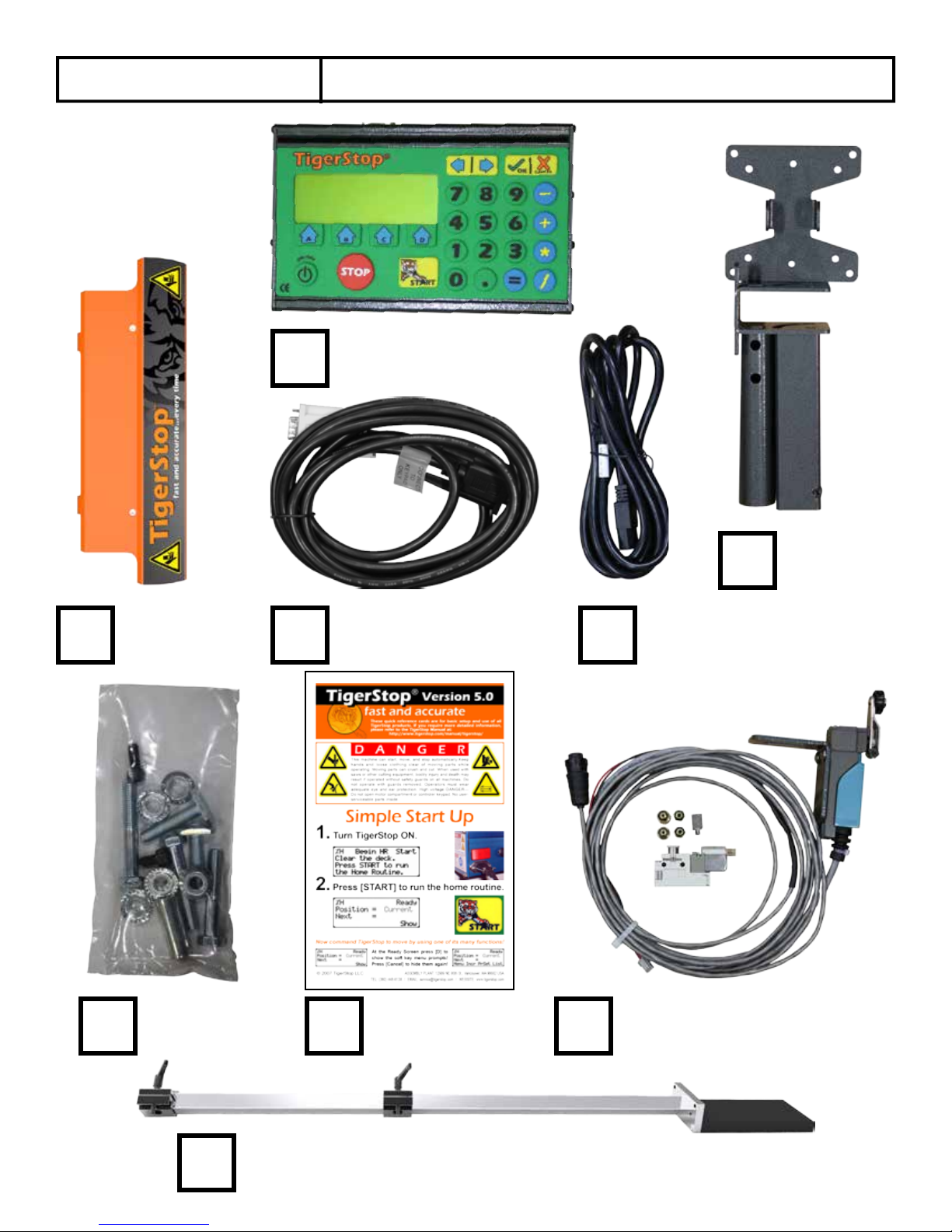
Controller
Controller
Stand
FlipAway
Stop
Nut Pack
Quick Reference
Cards
Power CableController Cable
Standard Interconnect Kit
Mini Gang Stop
2
Page 3
Safety First!
WARNINGS
INSTALLATION
WARNINGS
INTERCONNECTS
OPERATION
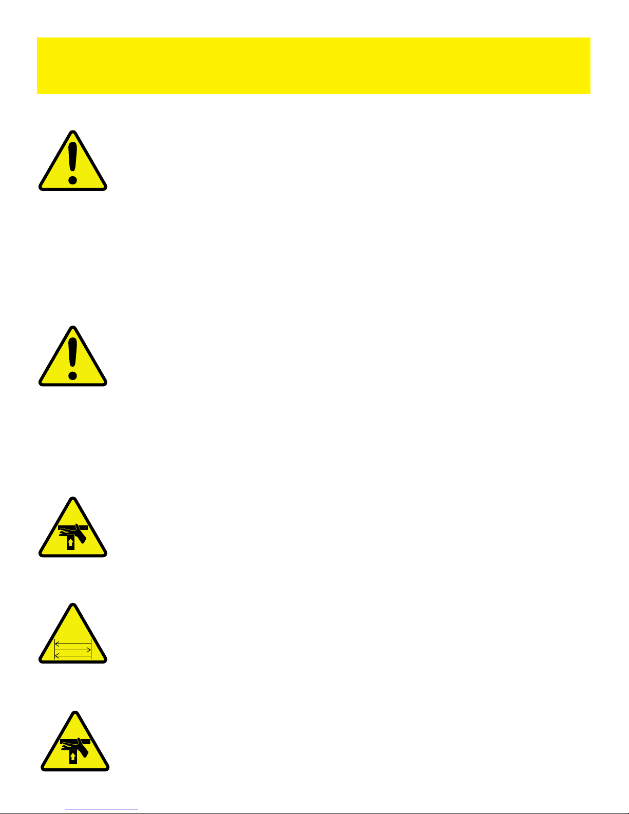
IMPORTANT SAFETY INFORMATION. READ ALL WARNINGS BEFORE OPERATING THIS PRODUCT.
WARNING: Installation of your TigerStop Product must be done by a person trained in the safe
design and installation of automation products, and in the safe operation of power equipment. Ensure
that such installation meets all legally required safety requirements and guidelines, and that proper
guarding and safety devices are provided on all sides of the equipment to preclude unintended access
during operation. Consult with and follow the recommendations of a qualifi ed safety engineer.
GENERAL
WARNING: TigerStop Products are components intended for use in conjunction with potentially
dangerous machinery. The use of TigerStop Products does not make other machinery safe. TigerStop
Products are not intended to substitute, in any manner, for safe operating practices in general, or for
safety features present in other machines designed to make those machines as safe as possible.
TIGERSTOP PRODUCTS, IF USED OR INSTALLED IMPROPERLY, MAY CAUSE PERSONAL
INJURY OR DEATH AND SHOULD ONLY BE OPERATED BY PERSONS TRAINED IN THEIR
SAFE OPERATING PROCEDURES. Illustrations of TigerStop Products in use do not show, and are
not intended to show, all safety features and practices necessary for their safe operation.
WARNING: TigerStop Products must be installed in accordance with all local, state, and federal
regulations. Only personnel properly trained in the safe design and installation of automation
machinery and related power equipment should install TigerStop Products onto other equipment, to
ensure a safe and proper work station. TigerStop Products should not be operated without proper
training, both in the operation of TigerStop Products, and in the operation of related equipment.
IMPORTANT CAUTION:
The motor box (compartment) contains DC voltage with potentially FATAL amperage. NEVER attempt
any unauthorized actions inside the motor box.
WARNING: Using a TigerStop interconnect does not relieve you of the responsibility for making sure
that your saw or other tool has all the necessary safety equipment in place. All installations must
meet all legally required safety requirements and guidelines. Installation and training should be done
following the recommendations of a qualifi ed safety engineer.
DANGER: This machine can start, move and stop automatically. Keep hands and loose clothing
clear of moving parts while operating. Moving parts can crush and cut. When used with a saw or
other cutting equipment, bodily injury and death may result if operated without safety guards on
all machines. Do not operate with guards removed. Operators must wear adequate eye and ear
protection.
DANGER! Don’t get pinched by the push feeder. Keep your hands away when in motion!
3
Page 4

IMPORTANT SAFETY INFORMATION. READ ALL WARNINGS BEFORE OPERATING THIS PRODUCT.
Keep the work area clean and well lighted to avoid accidental injury.
Do not use TigerStop machines in a dangerous environment. Using power tools in damp or wet
locations or in rain can cause shock or electrocution.
Do not operate near fl ammable liquids or in gaseous or explosive atmospheres!
Wear proper apparel, no loose clothes, long hair or jewelry which could get pulled into moving
machinery or materials.
Wear non slip footwear, safety glasses, ear protection and a dust mask.
Use only 3- wire extension cords that have 3-prong grounding type plugs and 3-pole receptacles that
accept the tools plug for 120VAC. Use only 5-wire cords and plugs when using 3 phase.
Do not open motor compartment or controller keypad. DC Voltage with potentially FATAL amperage!
Disconnect power before servicing. No user-serviceable parts inside.
DO NOT operate this or any machine under the infl uence of drugs or alcohol!
No one should operate this machine except for fully qualifi ed personnel.
Read the manual!
4
Page 5

Table of Contents
Table of Contents
Installation Requirements..............................................................................................6
TigerStop Installation....................................................................................................7
TigerStop Anatomy
Installation
Mounting TigerStop on the Right Side of your Tool
Install Flipaway Stop
Install Mini Gang Stop
Install Controller Stand
Install Standard Interconnect Kit
Final Connections
Enable Code..............................................................................................................14
Enabling Dynamic Optimization
First Power Up...........................................................................................................15
Calibration Settings
Set Zero End
Find the End Limits
Calibrate TigerStop
Set Kerf
Set Units
Set Optimizer Settings
Basic TigerStop Functions............................................................................................21
Entering Decimals
Entering Fractions
Calculator Mode
Jog
Increment
Preset
Quick Calibration
Working with Part Lists...............................................................................................25
Programing a List
Creating a Backboard Defecting & Optimizing List
Maintenance Schedule................................................................................................29
5
Page 6
Installation Requirements
Installation Requirements
TigerStop Power Requirements
110 VAC 15 Amps
208 VAC 20 Amps
240 VAC 20 Amps
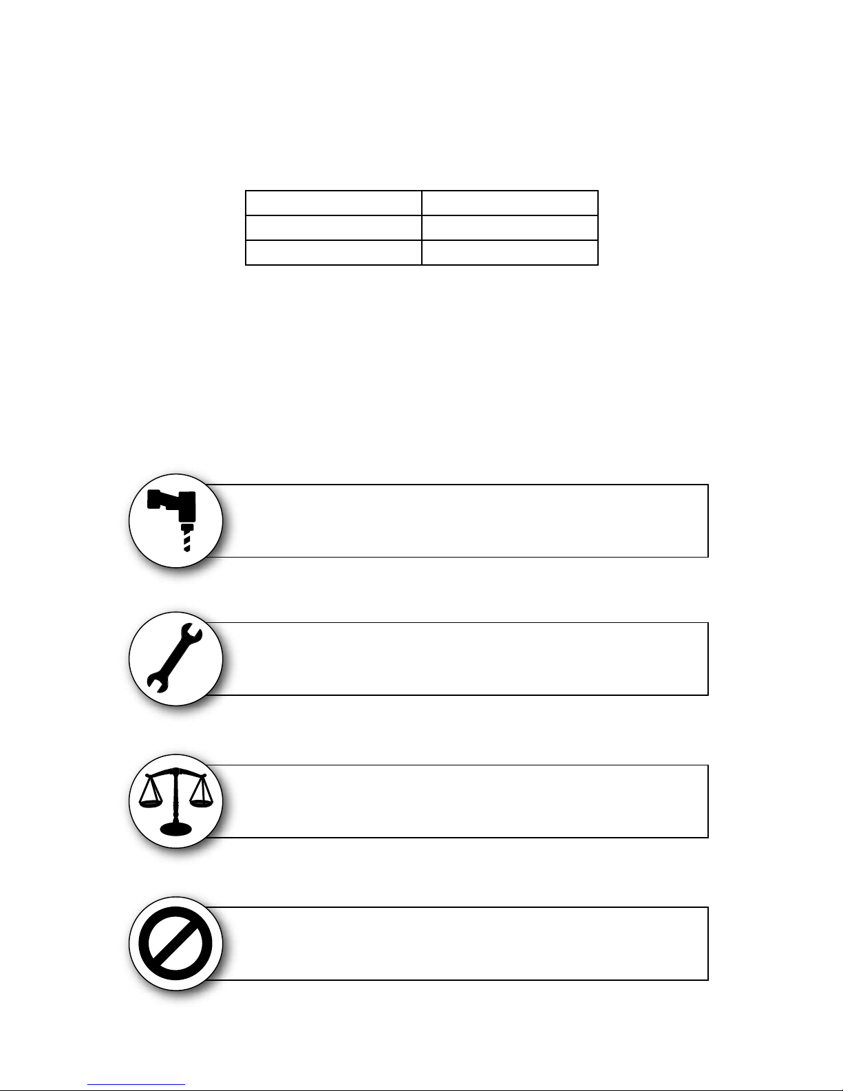
TigerStop must have a dedicated circuit. No other equipment or devices should be on the same circuit.
WARNING! Do NOT use a high leg delta circuit to power TigerStop.
If you are not sure what kind of circuit you are using, STOP! Have a qualified electrician confirm the main power circuit.
Do NOT drill or tap into the TigerStop beam!
Drilling holes into the TigerStop beam may damage the drive system. All fastening or
attachment to the fence beam must be made by inserting T-bolts or T-nuts with washers.
Do NOT over tighten mounting hardware!
It is critical, especially if not using the TigerStop Universal Attachment brackets, that the
bolts are prevented from over tightening and driving into the fence beam. Always use washers.
ALWAYS evenly tighten mounting hardware!
Uneven tightening of mounting hardware can introduce a slight twist or other deformation in the beam.
This will result in inaccurate measurement and premature failure of the drive belt or other components.
The motor box compartment contains DC voltage with potentially FATAL amperage.
6
NEVER open TigerStop Motor Box!
NEVER attempt unauthorized actions inside the motor box!
Page 7

TigerStop Installation
TigerStop Installation
TigerStop Anatomy
Motor Box
Flip away Stop
End Cap
Controller
TigerStop
Serial Number
Installation
Orange
Trim Strips
Attachment
Mounting Slots
Controller
Stand
Power Switch
&
Incoming Power
TigerStop
Mounting Slots
(Underside)
1. Unpackage and place TigerStop on the mounting surface with the motor box facing up.
2. Insert the T-Bolts from the hardware pack into the TigerStop mounting slots.
3. Rotate TigerStop so that the T-Bolts go through the holes in the mounting surface.
4. Attach the washer, lock washer and nut on each T-Bolt. Tighten evenly.
7
Page 8
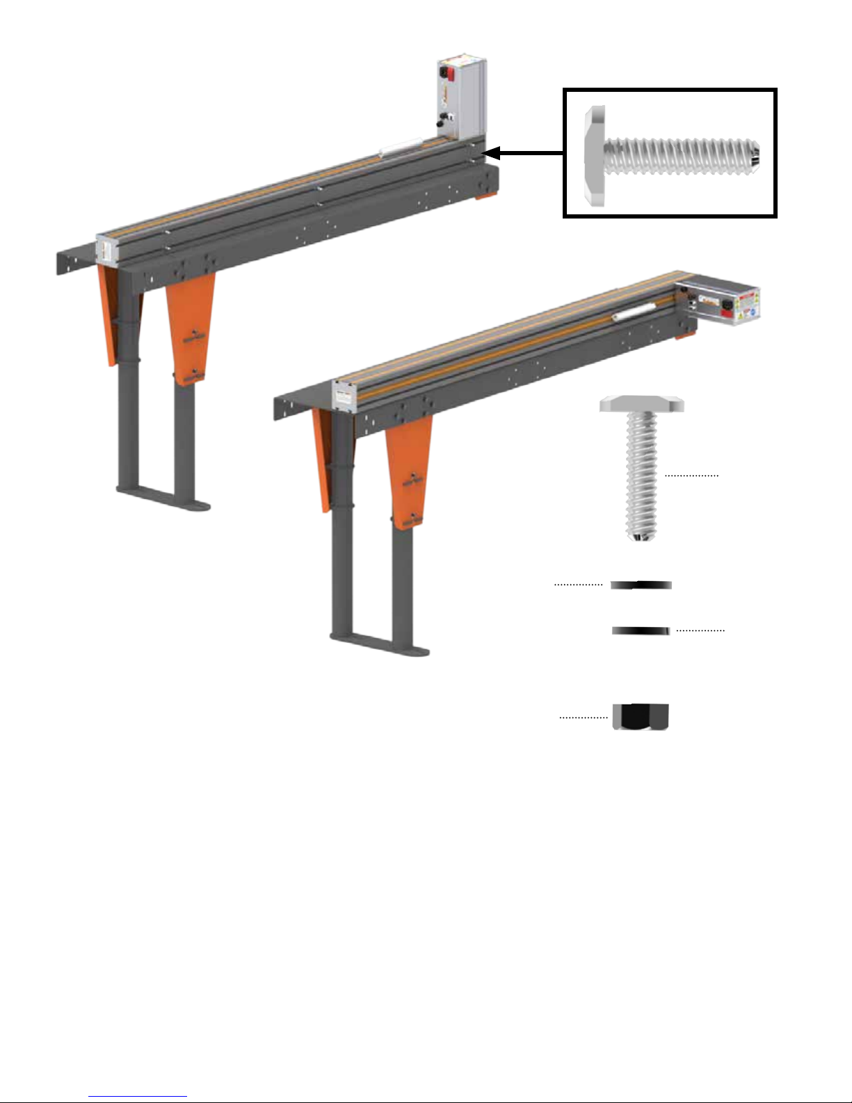
T-Bolt
Washer
Lock Washer
Nut
Mounting TigerStop on the Right Side of your Tool
From the factory, TigerStop is built to be installed on the left side of your tool. With very little
configuration, you can install TigerStop to the right side of the tool. The TigerStop has mounting slots on
both the top and the bottom of the beam. The top slots are filled with orange trim strips from the factory.
To mount TigerStop on the right side of your tool, simply remove the orange trim strips from the top
mounting slots, flip the machine over 180 degrees, and mount as normal.
8
Page 9
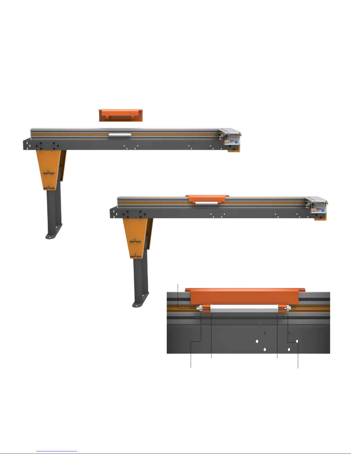
Install Flip Away Stop
Threaded
1. Place the flip away stop on the TigerStop carriage.
2. Insert a nylon washer between the carriage hinge and flip away stop hinge, one on each end.
3. Insert the threaded rod into the flip away stop.
4. Screw the locking nuts on each end of the threaded rod. Tighten so that when raised slightly, the flip
away stop says up.
Rod
Locking Nut
Nylon Washer
Nylon Washer
Locking Nut
9
Page 10
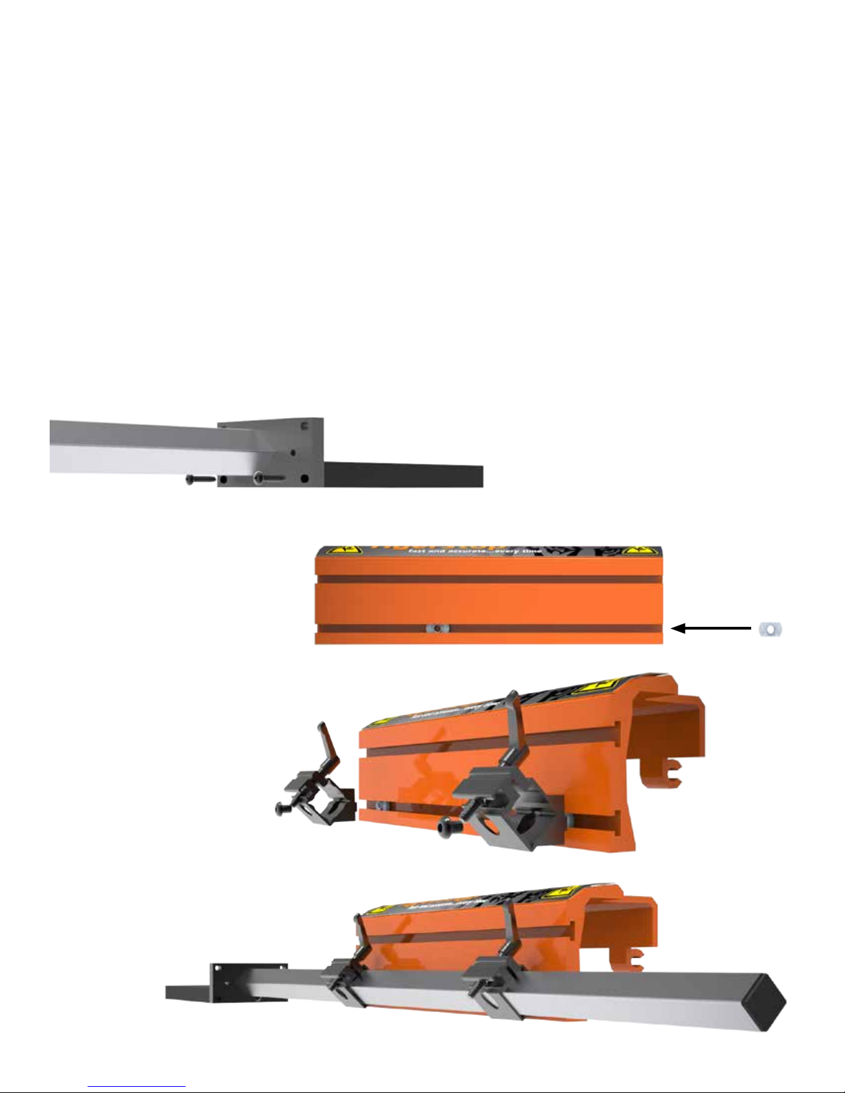
Install Mini GangStop
The Mini GangStop extends the reach of TigerStop so that you can reach the zero point of your tool.
Being able to reach 0 is essential for getting the best material yield when using your TigerStop Dynamic
Optimization feature.
The stop plate at the front of the Mini GangStop can be adjusted, by loosening the bolt, to
accommodate very thin materials or the PVC foot can be removed and the stop plate can be adjusted
to push materials that are stacked up.
1. Attach PVC foot to Mini GangStop stop plate.
2. Slide two T-Nuts into the lower channel of the flip away stop.
3. Connect the two tube retention blocks to the T-Nuts using two cap head screws.
4. Slide the Mini GangStop assembly into the tube retention blocks. Tighten down the locking handles.
10
Page 11
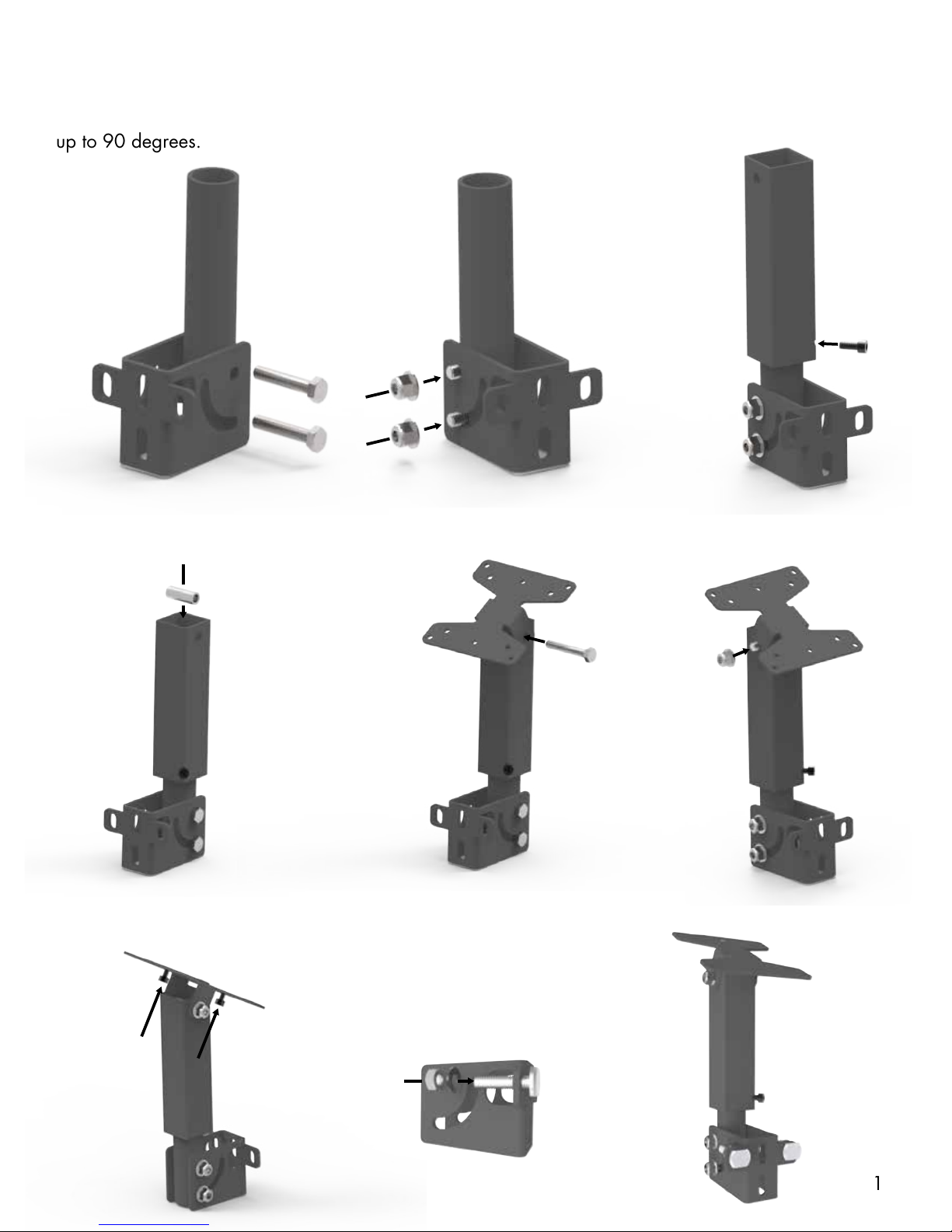
Install Controller Stand
1.
2.
3.
4. 5.
6.
7.
8.
9.
Attach to
TigerStop
The TigerStop controller stand will hold the TigerStop controller at a comfortable angle and height
during Backboard Defecting & Optimizing. The stand can be adjusted for a straight base or any angle
up to 90 degrees.
11
Page 12
Install Standard Interconnect Kit
The Standard Interconnect Kit integrates TigerStop with your tool. Once installed, TigerStop will know
when the tool is cycling and when the cycle is completed. This has a number of benefits:
Safety
When installed, TigerStop will be able to prevent the tool from cycling while the positioner is in motion.
TigerStop is also prevented from moving when the tool is in mid-cycle.
Automation
An additional benefit is partial automation of the tool, when using TigerStop’s Dynamic Optimization.
Once installed, TigerStop will know when the saw cycle is complete and will then move to the next part
size automatically, instead of waiting for the operator to signal for the next move. This dramatically
speeds up throughput and lowers material waste when performing Backboard Defecting & Optimizing
using TigerStop’s Dynamic Optimization upgrade.
WARNING! Using a TigerStop Standard Interconnect Kit does NOT relieve you of the responsibility
for making sure your saw or other tool has all the necessary safety equipment in place.
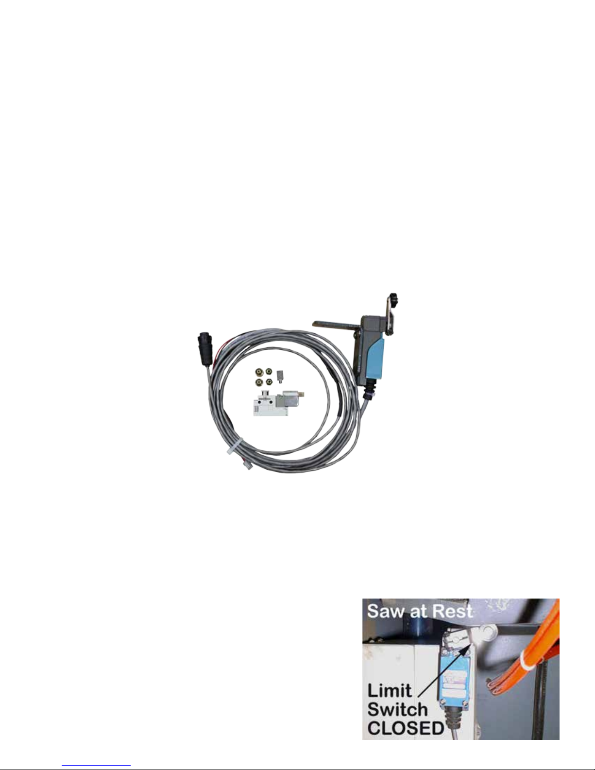
The TigerStop Standard Interconnect Kit has two components that integrate into your tool:
Mechanical Limit Switch
Mounted on the tool, this switch tells TigerStop if the tool is cycling.
Pneumatic Solenoid Valve
Plumbed into the air line that activates your tool, this solenoid valve will cut off air to the tool when
TigerStop is moving.
Mount the limit switch anywhere on the tool so that when the
tool is at its resting position, the switch is pressed.
Note: When the tool is cycled, the switch should become unpressed. When
the tool returns from the cycle, the switch should return to the pressed
position.
12
Page 13
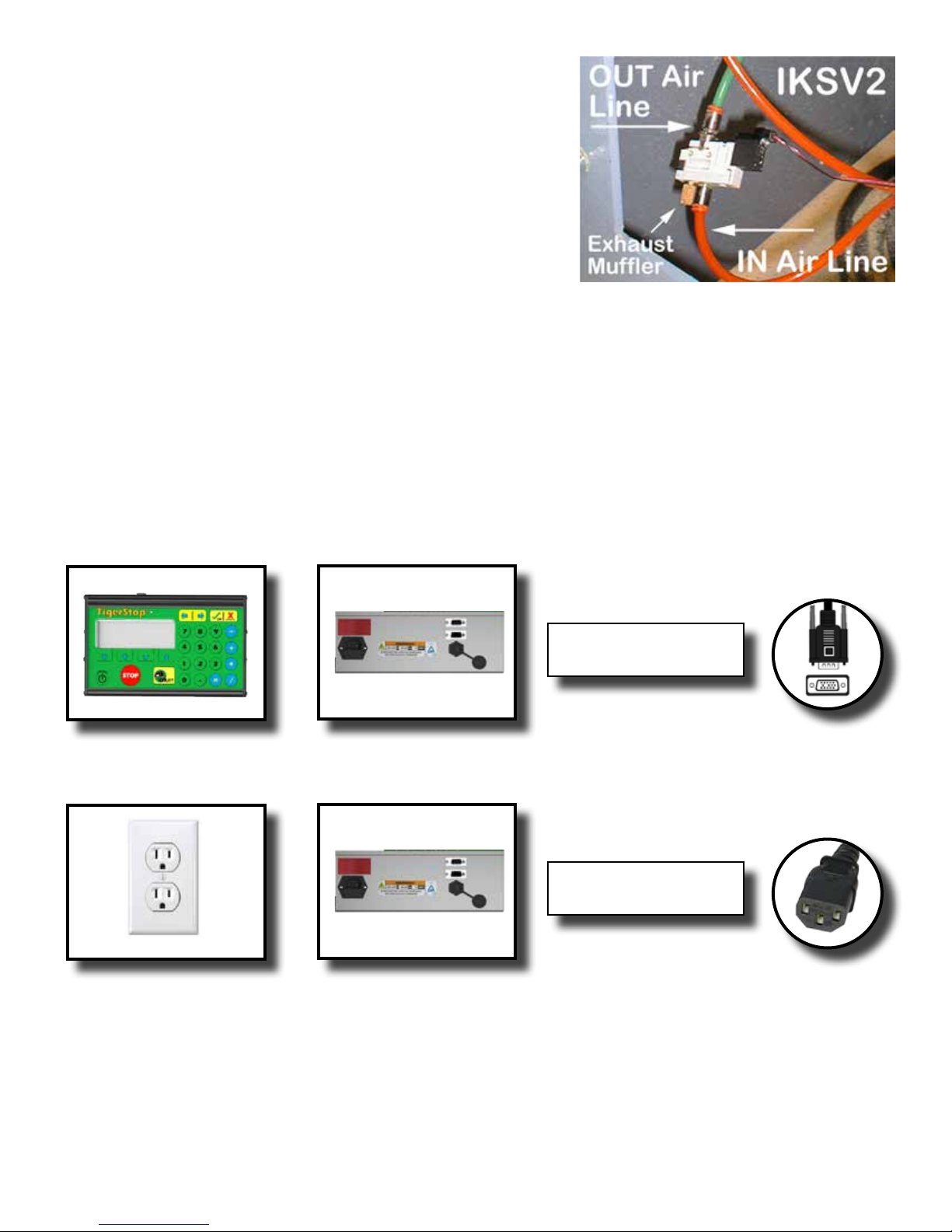
The Standard Interconnect Kit pneumatic solenoid must be
mounted inside your tool and integrated with the air supply.
The function of the air valve is to cut off air and disable the
tool while TigerStop is moving.
1. Find the air line that directly cycles your tool.
2. Cut this air line.
3. Put one side of the cut air line to the air input on the
solenoid valve.
4. Put the other side of the cut air line to the air output on the solenoid valve.
5. Connect the solenoid valve to the Standard Interconnect cable.
Final Connections
Once TigerStop and all TigerStop accessories are installed, it’s time to make the final connections.
1. Connect the TigerStop Controller Cable to the Controller and Motor Box.
Note: The TigerStop Controller Cable is a proprietary cable. DO NOT use an “off the shelf” cable. Doing so can cause
damage to TigerStop.
White End (Motor Box)
Black End (Controller)
15 Pin
Controller
TigerStop Motor Box
2. Connect the TigerStop power cable from your power outlet to the TigerStop incoming power plug.
Black TigerStop
Power Cable
Power Outlet
TigerStop Motor Box
Power Cable
13
Page 14
Enable Code
Enable Code
Your new TigerStop will not function until you enter the TigerStop enable code, which is supplied by
TigerStop Customer Service.
The enable code notifies TigerStop, LLC when your new TigerStop is about to be put into service. This
lets us start the warranty on the exact day you turn it on. The enable code also allows TigerStop to turn
on your TigerStop Dynamic Optimization upgrade.
How to Enable TigerStop
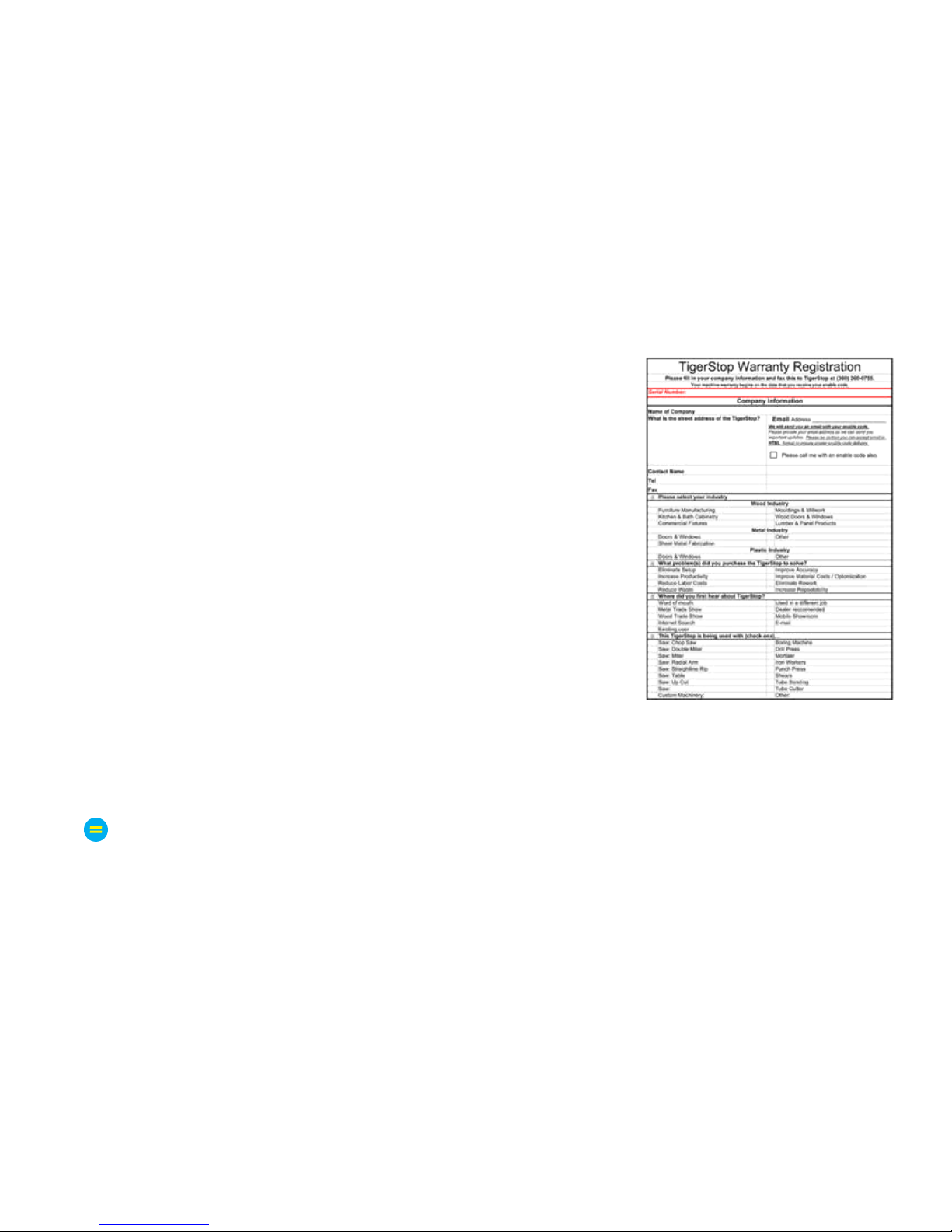
1. Fill out the TigerStop Warranty Registration sheet that is shipped
with your TigerStop controller.
Fax or email the registration to:
(360) 260-0755
You may also register your warranty by phone:
TigerStop Customer Service
(360) 254-0661
TigerStop Customer Service will contact you by phone to give you the
enable code, within the hour during regular business hours, Monday
through Friday 6:00 am - 4:00 pm PST.
2. When you have received your enable code, power up TigerStop using the power switch on the
motor box.
3. TigerStop will ask you to enter your enable code. Enter the code received from TigerStop and press
.
Your TigerStop has now been enabled.
Enabling Dynamic Optimization
The Dynamic Optimization enable code upgrade is necessary to use TigerStop to its fullest potential.
TigerStop can run an optimizing algorithm that will find the mathematically perfect way to cut your
material. This can decrease material waste by up to 40%. Dynamic Optimization also enables you to
defect your material using the Backboard Defecting & Optimization method, shown on page 26,
allowing you to cut defects out of your material and optimize the yield of the good material.
Ask TigerStop Customer Service about Dynamic Optimization!
14
Page 15
First Power Up
First Power Up
After entering the enable code, TigerStop will ask to run the ‘Home Routine’.
Home Routine Explained
Every time TigerStop is powered up, it performs the ‘Home Routine’. The home routine is a 3 step
process where TigerStop will move to its farthest possible position.
1. Press
2. When movement stops, TigerStop will display the Ready Screen.
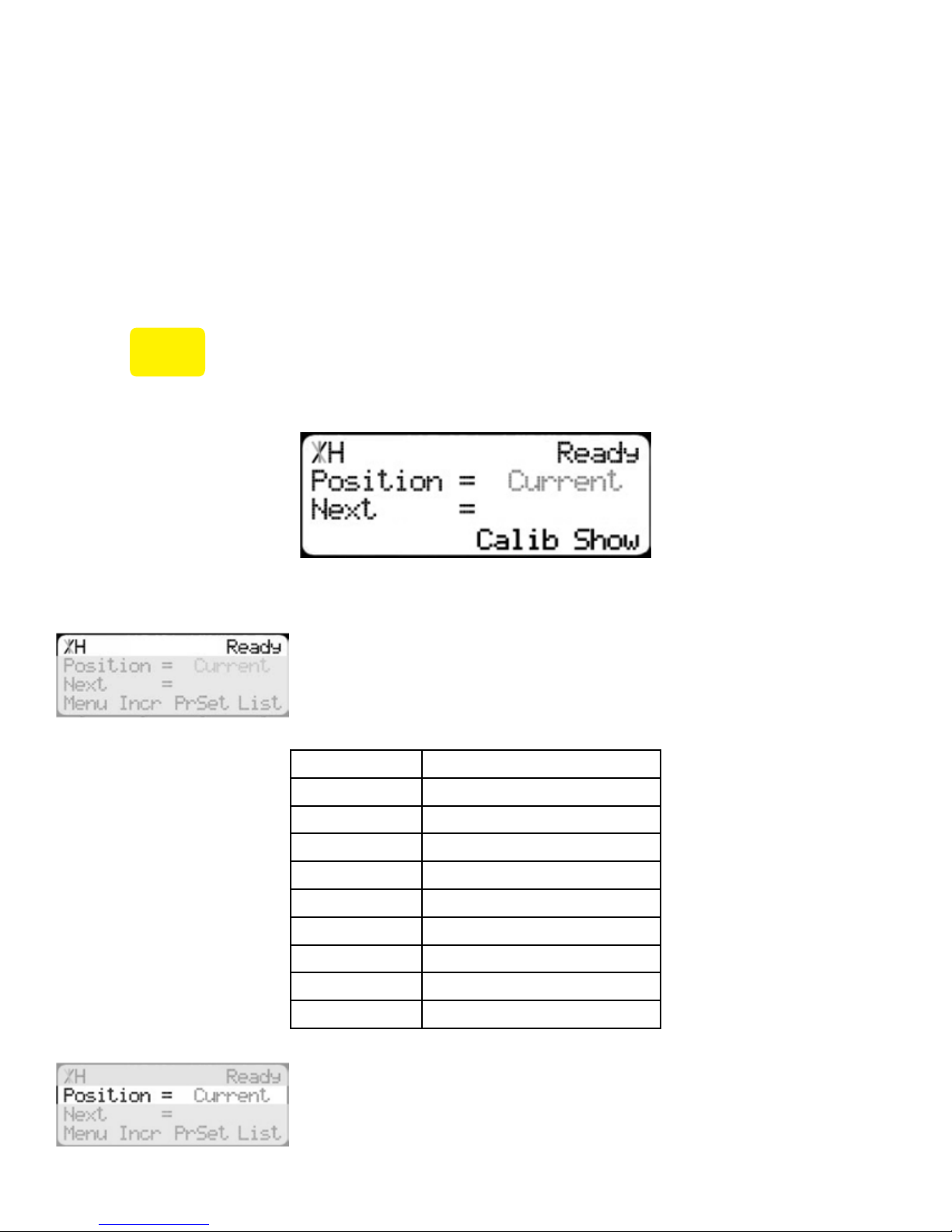
The Ready Screen is the starting point for all TigerStop functions. Let’s take a look at the screen, line by
line.
START
to run the Home Routine.
Line 1 displays the “heartbeat”. The heartbeat is a line that rotates and
lets you know that TigerStop is functioning normally. The letter next
to the heartbeat is the drive indicator. This tells you what the motor is
doing.
Drive Indicator Meaning
H Holding Still
Line 2 shows the current position of TigerStop. The position will show
with ‘in’ when in inches mode and ‘mm’ when in metric mode.
A Accelerating
C Moving at Constant Speed
D Decelerating
W Waiting
S Stopping
T Waiting for Text Entry
X E-stop Error
N Communication Error
15
Page 16
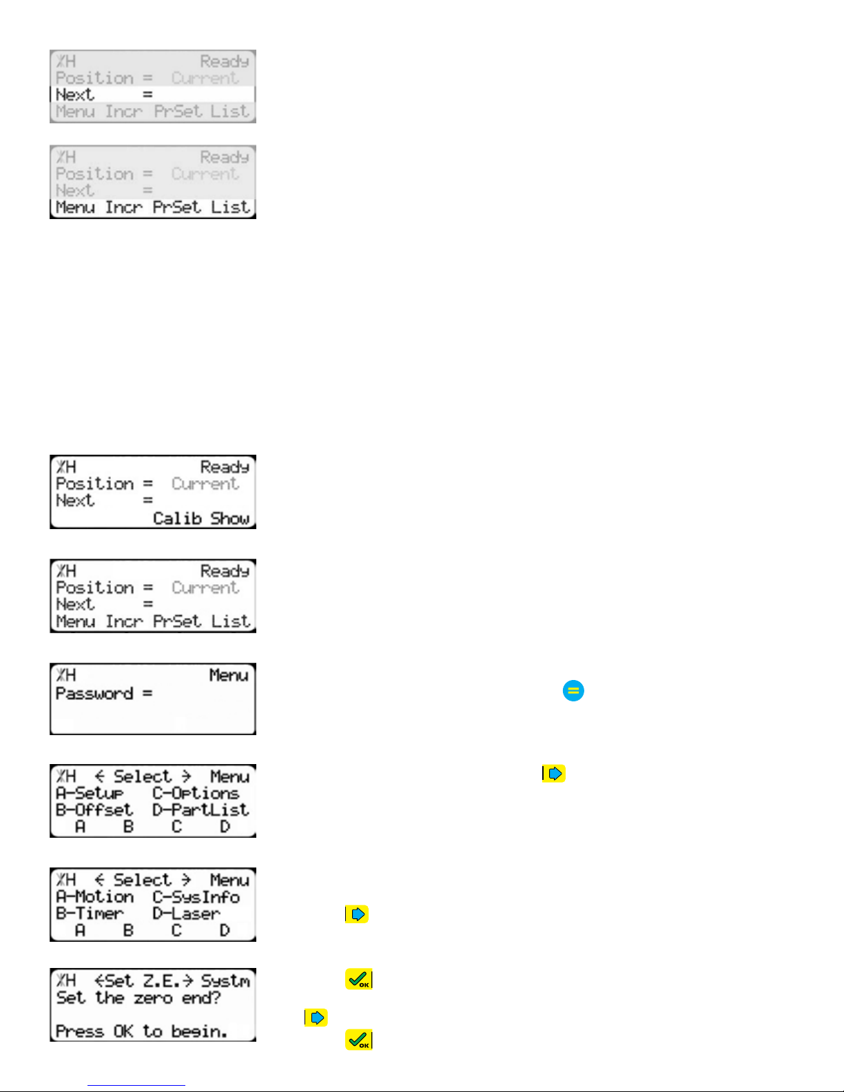
Line 3 shows the next position of Tigerstop. This is where user input is
shown.
Line 4 displays the soft key prompts. These prompts tell you what the
soft key button below it does. These can change when you access
different screens.
Calibration Settings
Once homed, we will need to set a few settings to ensure TigerStop is measuring properly for your
application. Some of these settings are critical for the operation of TigerStop Dynamic Optimization
and Backboard Defecting & Optimizing.
Set Zero End
If you have installed TigerStop on the right side of the tool, or if you have positioned the motor box
away from the tool, you will need to toggle the zero end setting. This will tell TigerStop to measure in
the opposite direction. If you have installed TigerStop on the left, you may skip this setting.
1. From the Ready Screen, press the [Show] soft key to show the menu
options.
2. Press the [Menu] soft key to display the Menu Select screen.
3. TigerStop requires a password to access all menu options. Enter
your TigerStop password and press
Note: By default, the TigerStop password is set to the serial number.
.
4. At the Menu Select screen, press one time.
5. Press the [SysInfo] soft key to access the System Information menu.
6. Press to scroll through the settings. Stop when you see Set Z.E.
7. Press to begin.
8. TigerStop will display your current Zero End configuration. Press
16
9. Press
to toggle the setting.
to enter the new setting.
Page 17
10. Follow the on screen prompts to run the Home Routine.
STOP
11. When the home routine is finished, press
to return to the Ready Screen.
Find the End Limits
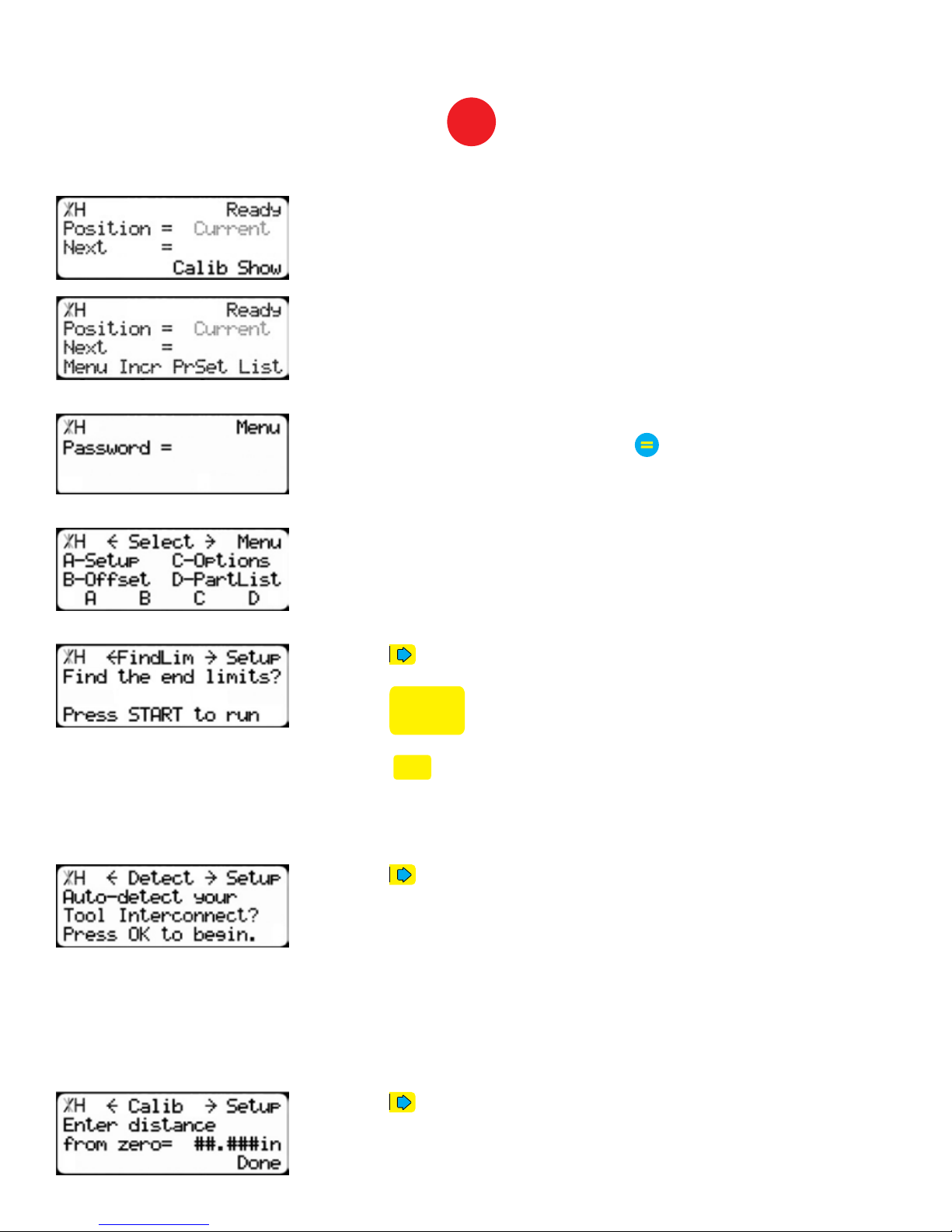
1. From the Ready Screen, press the [Show] soft key to show the menu
options.
2. Press the [Menu] soft key to display the Menu Select screen.
3. TigerStop requires a password to access all menu options. Enter
Auto Detect
your TigerStop password and press
Note: By default, the TigerStop password is set to the serial number.
.
4. At the Menu Select screen, press the [Setup] soft key to access the
Setup Menu.
5. Press to scroll through the settings. Stop when you see FindLim.
6. Press
Note: Ensure TigerStop can move its entire length without obstruction. TigerStop will
move once
START
START
is pressed.
to run the Find End Limit routine.
1. Press to scroll through the settings until you get to the Auto
detect setting.
2. Follow the prompts on screen to detect your Interconnect Kit.
Calibrate TigerStop
1. Press to scroll through the settings until you get to the Calib
setting.
17
Page 18
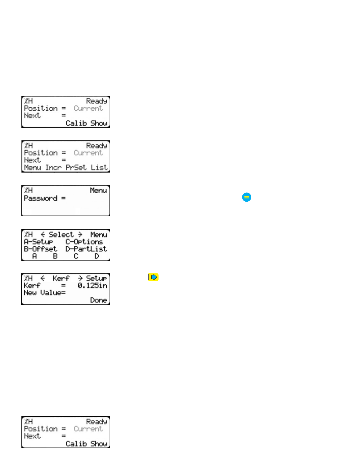
2. Measure how far the TigerStop is from your tool’s zero point.
3. Enter this measurement and press the [Done] soft key.
Note: TigerStop has been calibrated and you will be taken back to the Ready Screen.
Set Kerf
If the tool you have installed TigerStop to is a cutting tool, you will need to set the kerf setting. The kerf
is the measure of how much material is destroyed by the saw blade during a cut.
1. From the Ready Screen, press the [Show] soft key to show the menu
options.
2. Press the [Menu] soft key to display the Menu Select screen.
3. TigerStop requires a password to access all menu options. Enter
your TigerStop password and press
Note: By default, the TigerStop password is set to the serial number.
.
4. At the Menu Select screen, press the [Setup] soft key to access the
Setup menu.
5. Press to scroll through the settings. Stop when you get to the
Kerf setting.
To measure kerf...
1. Cut a sample piece and measure it with a caliper. Record your measurement
2. Cut this piece in half.
3. Put the two pieces together as if they were one piece and re-measure with a caliper.
4. The difference between the measurement on step 1 and the measurement on step 3 will be your new
kerf value.
5. Enter your kerf value and press the [Done] soft key to save the parameter.
Note: It is important to check and reset the kerf every time the saw blade is changed or sharpened.
Set Units
TigerStop can display its position in inches or metric.
1. From the Ready Screen, press the [Show] soft key to show the menu
18
options.
Page 19
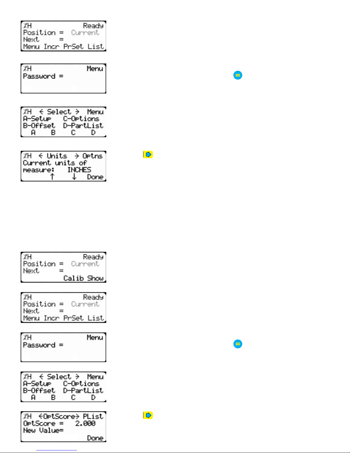
2. Press the [Menu] soft key to display the Menu Select screen.
3. TigerStop requires a password to access all menu options. Enter
your TigerStop password and press
Note: By default, the TigerStop password is set to the serial number.
.
4. At the Menu Select screen, press the [Options] soft key to access the
Options menu.
5. Press to scroll through the settings. Stop when you get to Units.
6. Press [B] to toggle between inches and metric.
7. Press the [Done] soft key when finished.
Set Optimizer Settings
TigerStops Dynamic Optimizer is tuned from the factory to give the best overall material yield.
However, the optimizer can be configured differently if you have different requirements.
Optimizer Score
1. From the Ready Screen, press the [Show] soft key to show the menu
options.
2. Press the [Menu] soft key to display the Menu Select screen.
3. TigerStop requires a password to access all menu options. Enter
your TigerStop password and press
Note: By default, the TigerStop password is set to the serial number.
.
4. At the Menu Select screen, press the [PartList] soft key to access the
Part List menu.
5. Press to scroll through the settings until you get to the Opt Score
setting.
19
Page 20
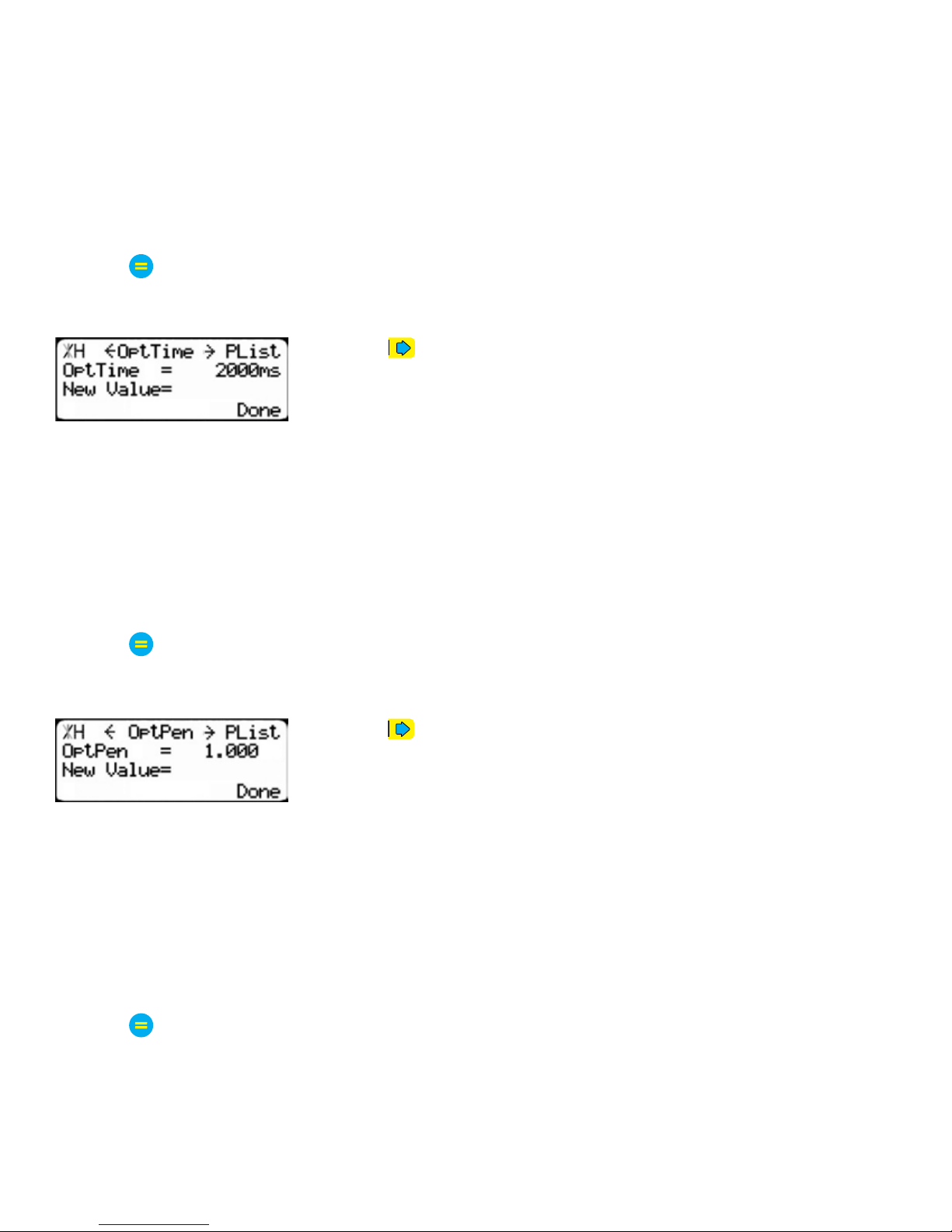
The Optimizer Score setting sets the score that the optimizer solution must reach to be considered a
good solution.
A lower Opt Score setting will give you a better optimized solution, but will take longer to do so.
A higher Opt Score setting will give you a faster solution, but it may give you a lower material yield.
To change Opt Score...
1. Enter the new Opt Score setting.
2. Press
to save the parameter.
Optimizer Time
1. Press to scroll through the settings until you get to the Opt Time
setting.
The Optimizer Time setting sets the amount of time the TigerStop Optimizer has to find a solution. If it
takes longer than this time, TigerStop will use the best found optimized solution.
A lower Opt Time setting will give you a faster solution, but it may give you a lower material yield.
A higher Opt Time setting will give you better material yield, but it may take longer to do so.
To change Opt Time...
1. Enter the new Opt Time setting.
2. Press
to save the parameter.
Optimizer Penalty
1. Press to scroll through the settings until you get to the Opt Pen
setting.
The Optimizer Penalty setting sets a penalty for multiple board optimized solutions. This means that the
higher this setting, the more TigerStop will try to cut longer parts first.
A lower Opt Pen setting will give you faster optimization with more short parts processed first.
A higher Opt Pen setting will give you a slower optimization with more long parts processed first.
To change Opt Pen...
1. Enter the new Opt Pen setting.
2. Press
to save the parameter.
By adjusting these three optimizer settings, you can greatly influence how the TigerStop optimizer works
to suit your exact application.
20
Page 21
Basic TigerStop Functions
Basic TigerStop Functions
Manual Movement
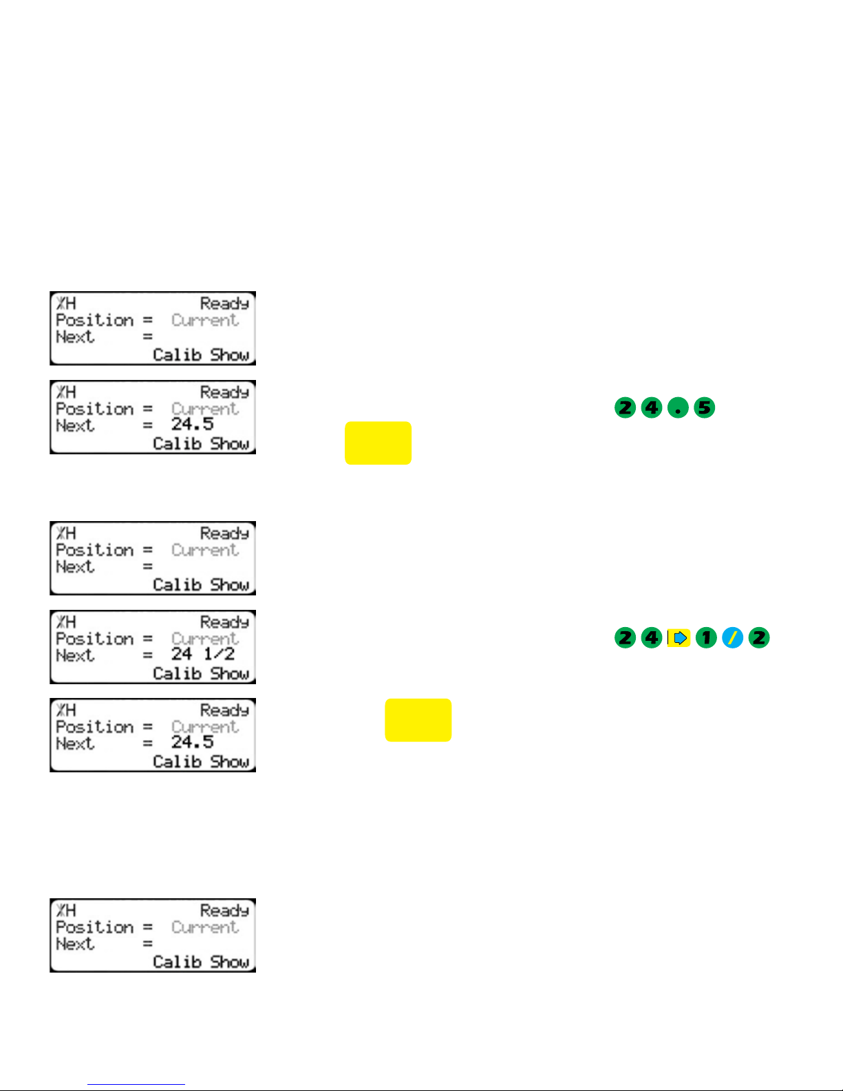
To manually move TigerStop to a position, you must enter the length you want TigerStop to go to. This
length can be entered as a decimal or a fractional value.
Entering Decimals
1. Start at the Ready Screen.
2. Enter a length at the controller.
Entering Fractions
Example: To enter 24 1/2 as a decimal, enter
3. Press
4. Start at the Ready Screen.
5. Enter a length at the controller.
Example: To enter 24 1/2 as a decimal, enter
6. Then press
Notice that even though you entered a fraction, TigerStop will display
the position as a decimal once it has moved. TigerStop cannot display
fractions in the ‘Position’ field.
START
to move TigerStop.
START
to move TigerStop.
.
.
Calculator Mode
TigerStop has a calculator function that can be used to do simple math problems.
1. Start at the Ready Screen.
21
Page 22
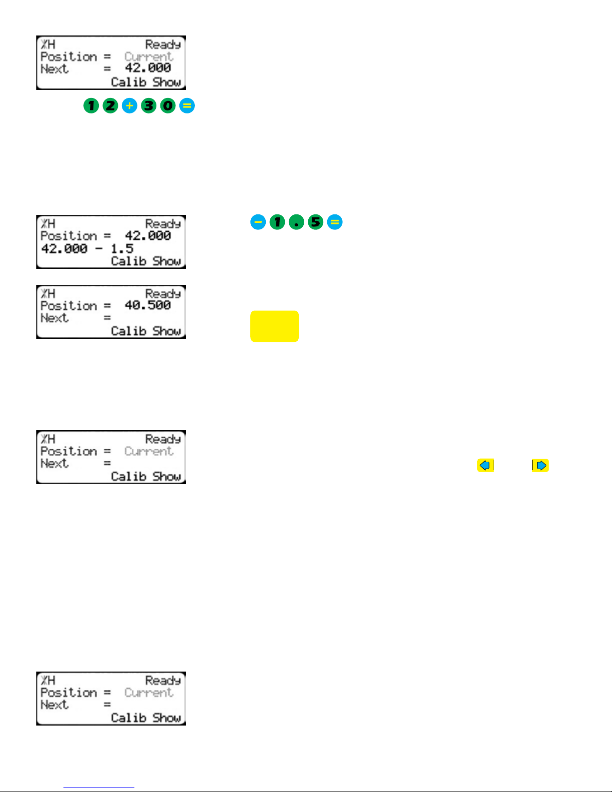
Just like a normal calculator, you can use the math function keys to
enter math problems.
Example: I want to add 12 inches to 30 inches.
2. Press
.
The answer will appear in the ‘Next’ field.
3. Press [Start] and TigerStop will move to the calculated position.
You can also do math functions on the current position.
Example: I want to subtract 1.5 inches from my current position of 42 inches.
1. Press .
The answer will appear in the ‘Next’ field.
START
2. Press
and TigerStop will move.
Jog
TigerStop can be manually jogged in or out. When activated, TigerStop will move until you let go of the
jog button. It will then glide to a gentle stop.
1. Start at the Ready Screen.
2. At the top of the TigerStop controller, you have a
and a . To
jog, press and hold one of these buttons.
Note: If the jog buttons move TigerStop in the wrong direction, you can use the ‘Jog
Reverse’ setting in the ‘Setup’ menu to reverse the movement.
Increment
The increment function is a push feed mode used to step TigerStop through a series of movements.
Increment...
• Can be a positive value that will move TigerStop towards the tool.
• Can be a negative value that will move TigerStop away from the tool.
• Will compensate for kerf automatically using the ‘Kerf’ setting in the ‘Setup’ menu.
• Can only store one increment value at a time.
1. Start at the Ready Screen.
2. Press the [Show] soft key to display more options.
22
Page 23
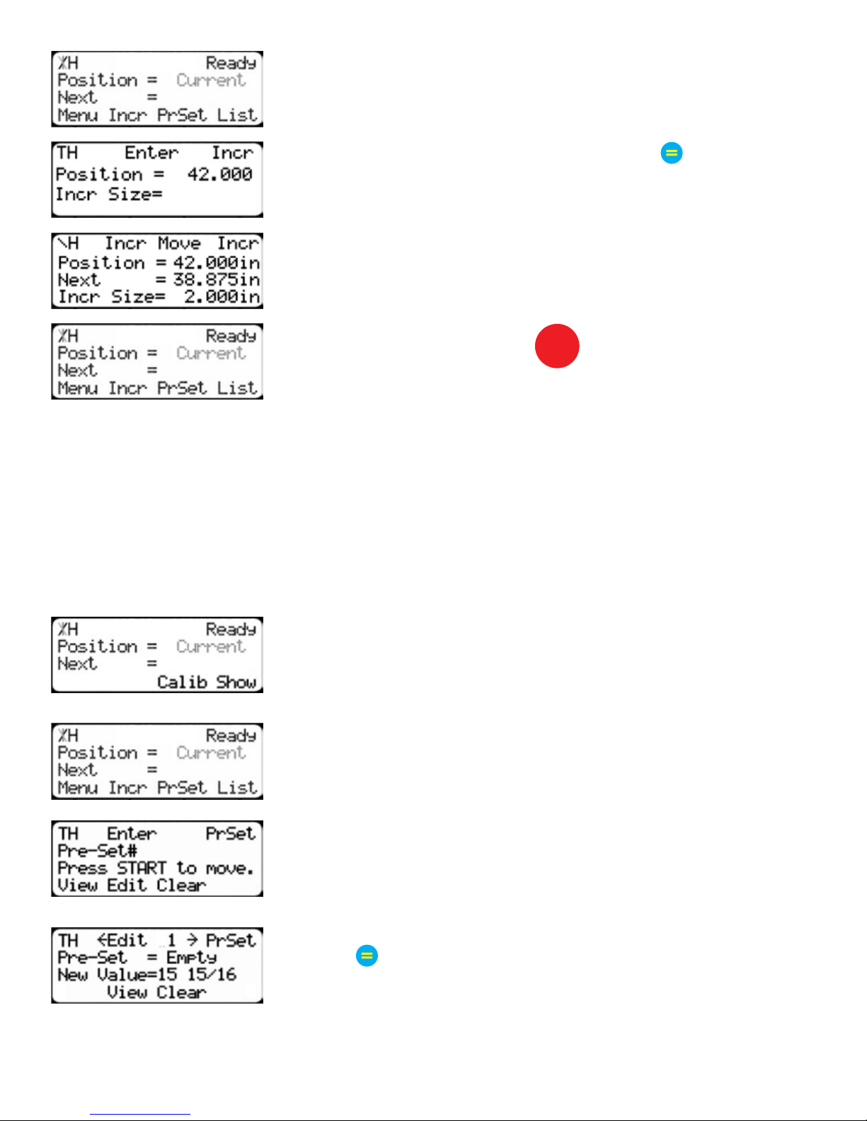
3. A new set of options have appeared. Press the [Incr] soft key to
access the Increment menu.
4. Enter the size you want to increment and press .
For this example, I am going to use an increment of 2 inches.
5. The current position is 42. If that is where you want to start, press
[Start] to begin incrementing. If you need to move TigerStop to load
your stock, enter the position and press [Start]. TigerStop will move
to position. Load your stock and press [Start] to begin incrementing.
STOP
6. When you are finished, press
to return to the Ready Screen.
PreSet
The PreSet function is a set of 100 programmable hot keys used to quickly access common lengths.
PreSets...
• Can be used in Set Point, Pusher or Increment mode.
• Can be programed in PreSet slots number 1 - 100.
Note: PreSet functionality can be changed using the ‘PreSet’ setting in the Part List menu.
PreSet Programming
1. From the Ready Screen, press the [Show] soft key to show the menu
options.
2. A new set of soft key options have appeared. Press the [PrSet] soft
key to access the PreSet feature.
3. Enter the number of the preset you want to program and press the
[Edit] soft key.
4. For this example, I am going to program PreSet number 1.
5. Enter the length you want the PreSet to move TigerStop to, and
press
.
23
Page 24
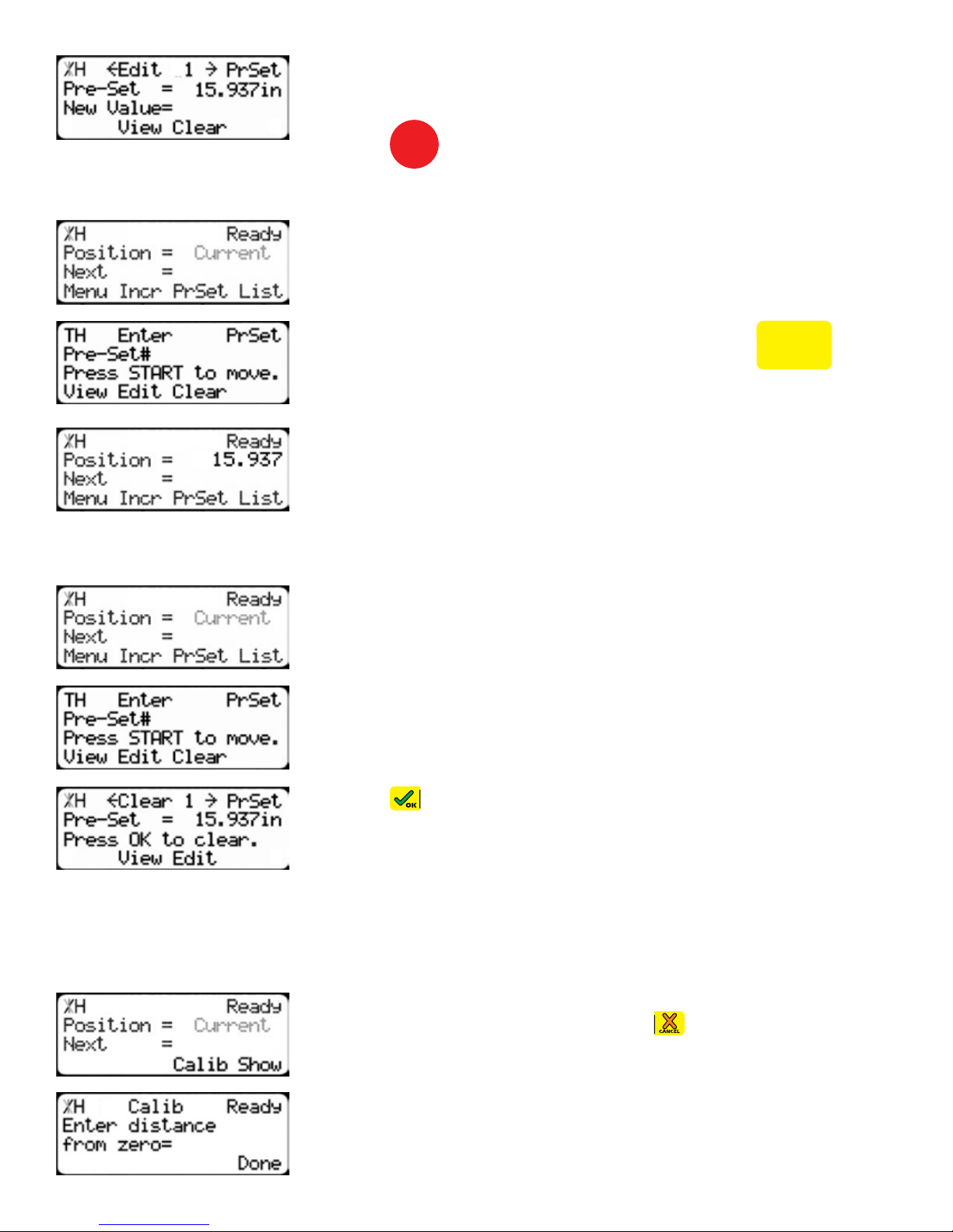
Using the PreSet
For this example, I want to move to 15 15/16 inches.
6. The PreSet value is now set.
STOP
7. Press
to go back to the Ready Screen.
1. Start at the Ready Screen.
2. Press the [PrSet] soft key to access the PreSet menu
Deleting PreSets
3. Enter the PreSet number you wish to use and press
START
.
4. TigerStop will move to the PreSet position.
1. Start at the Ready Screen.
2. Press the [PrSet] soft key to access the PreSet menu.
3. Enter the PreSet number you wish to delete and press the [Clear]
soft key.
4. Press to clear.
5. TigerStop has now deleted the PreSet.
Quick Calibration
Quick calibration is a shortcut to the calibration setting. This allows more advanced TigerStop users to
quickly calibrate TigerStop.
1. Start at the Ready Screen.
Note: if you viewing the expanded options, press .
2. Measure how far the TigerStop is from your tool’s zero point. Enter
3. TigerStop is now calibrated.
24
this measurement and press the [Done] soft key.
Page 25
Working with Part Lists
Working with Part Lists
TigerStop has a versatile part list feature that allows users to enter large lists of part for use with the
TigerStop Dynamic Optimization upgrade. This lets the user run, view, edit, clear and optimize lists of
parts, then processes the parts quickly and accurately.
There are 4 types of lists that you can enter.
Pusher
A pusher list will tell TigerStop to push the material into the tool. You can enter as many parts as you
like into a pusher list and TigerStop will tell you when it needs another piece of material. Pusher lists
can be optimized if you have the TigerStop Dynamic Optimizing upgrade.
Set Point
A set point list will tell TigerStop to act as a stop. It will treat each length you enter as an absolute value
from your zero point. Set point lists can be optimized if you have the TigerStop Dynamic Optimizing
upgrade.
Pattern
A pattern list will tell TigerStop to process one stock lengths worth of parts in a push feed fashion. It will
run the same pattern of parts until its told to stop. Pattern lists cannot be optimized.
Pull
A pull list works just like a pattern except it pulls away from the zero point instead of pushing towards
it. Pull lists cannot be optimized.
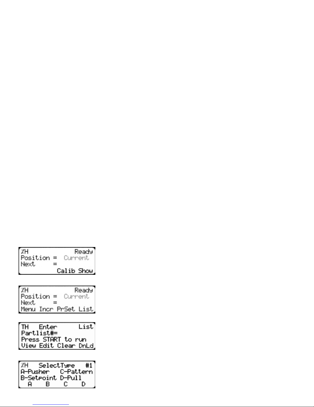
Programming a List
1. From the Ready Screen, press the [Show] soft key to show the menu
options.
2. A new set of soft key options have appeared. Press the [List] soft key
to access the List interface.
3. At the List interface, enter the list number you wish to program and
press the [Edit] soft key.
Note: the list number is a memory slot that houses the list. You can choose numbers
1 - 100.
4. Select the type of list you would like to program.
25
Page 26
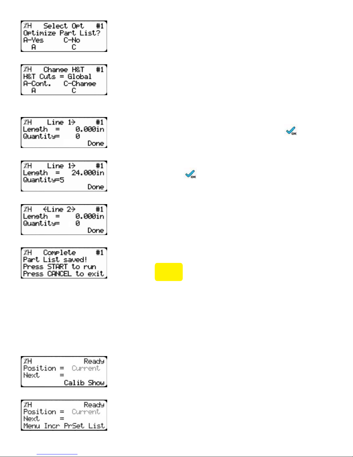
5. TigerStop will ask you if you want to optimize the list for material
yield. If you choose no, TigerStop will process the list exactly as
entered and will NOT optimize for material yield.
6. Select if you want to use a global or a local head and tail cut.
Note: Head and tail cuts are trim cuts at the ends of your material.
Global - Uses the head and tail cut setting from the Part List menu
Local - Allows you to set a head and tail cut that is used for this list only.
7. You will now be taken to the programming screen for line 1. Enter
the length of the part you wish to process and press .
In this example, I will tell TigerStop I want to cut a 24 inch part.
8. The cursor will now drop to the quantity. Enter how many parts you
want, followed by .
In this example, I will tell TigerStop that I want 5 parts.
9. You will now be taken to line 2. Repeat steps 7 and 8 until you
have entered all the parts you want to process.
Note: You can also download all the parts straight from your design file.
Downloading is a faster way of importing parts for use with the TigerStop Optimizer.
10. Press the [Done] soft key when all parts are entered.
11. The list has now been saved.
12. Press
START
to run the list.
Creating a Backboard Defecting & Optimizing List
Backboard Defecting & Optimizing is a process that allows you to quickly and easily cut around
material defects while optimizing the clear stock for better material yield. It is accomplished using a
standard Set Point list, TigerStop’s Dynamic Optimization upgrade and a back fence ruler.
Program a Set Point List
1. From the Ready Screen, press the [Show] soft key to show the menu
options.
2. A new set of soft key options have appeared. Press the [List] soft key
26
to access the List interface.
Page 27
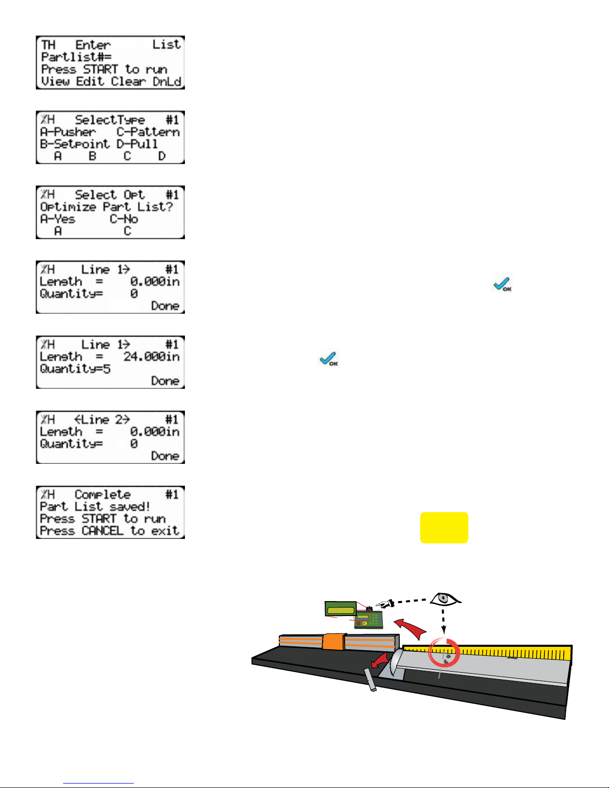
3. At the list interface, enter the list number you wish to program and
press the [Edit] soft key.
Note: the list number is a memory slot that houses the list. You can choose numbers
1 - 100.
4. Choose Set Point list.
5. TigerStop will ask if you want to optimize. Choose Yes.
Note: If you do not see this option, contact TigerStop Customer Service.
6. You will now be taken to the programming screen for line 1. Enter
the length of the part you wish to process and press .
In this example, I will tell TigerStop I want to cut a 24 inch part.
7. The cursor will now drop to the quantity. Enter how many parts you
want, followed by
In this example, I will tell TigerStop that I want 5 parts.
8. You will now be taken to line 2. Repeat steps 6 and 7 until you
have entered all the parts you want to process.
Note: You can also download all the parts straight from a design file. Downloading is
a faster way of importing parts for use with TigerStop Dynamic Optimization.
9. Press the [Done] soft key once you have entered all parts.
10. The list has now been saved. Press
Running the list
1. First, make your trim cut. After the
trim cut, measure up to your first
defect.
Note: If no defect is present, measure up to the
end of the material.
.
TigerStop
TigerStop
20in
START
to run the list.
TigerStop
TigerStop
20in
START
20
1 0
2 0
3 0
4 0
5 0
6 0
7 0
27
Page 28
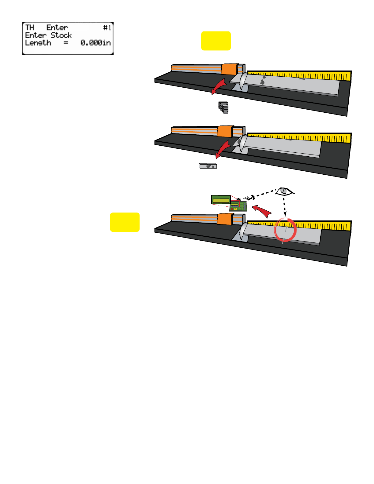
2. TigerStop will ask you to enter the stock length. Enter what you
measured and press
3. TigerStop will optimize the
material up to the defect and will
use as much of the material as
mathematically possible.
Note: If you are using the Standard
Interconnect Kit, TigerStop will move to the next
part length when tool cycle is complete.
4. Cut out your defect.
5. TigerStop will once again ask you
to enter the stock length. Measure
up to the next defect, enter this
measurement and press
START
Note: If no defect is present, measure up to the
end of the material.
.
START
TigerStop
TigerStop
30in
.
1 0
2 0
3 0
4 0
5 0
6 0
7 0
1 0
2 0
3 0
4 0
5 0
6 0
7 0
TigerStop
TigerStop
26.5in
START
30
1 0
2 0
3 0
4 0
5 0
6 0
7 0
6. TigerStop will optimize the material up to the defect and will use as much of the material as
possible.
7. Continue in this fashion until the entire stock is used. If you have more parts to cut, start at step 1
with a new piece of material.
Why Use BackBoard Defecting & Optimizing?
• Dynamic Optimization™ determines the best use of material, so the operator (unskilled worker or pro
fabricator) only has to focus on feeding parts and cutting.
• TigerStop® moves to the correct position up to .004” so the operator never has to use a tape
measure or set a manual stop ever again.
• TigerStop® reduces station setup time between different cut lengths and allows the operator to
optimize for defects like forklift stabs, shipping damage, dents, or aesthetic blemishes, while getting
optimal yield.
• TigerStop® increases accuracy. The operator doesn’t have to worry about cutting errors or the
associated costs of rework. Quality control concerns are no longer a bottleneck.
• Dynamic Optimization™ reduces scrap waste and shelving costs. Purchase less raw footage while
28
Page 29

sending fewer pounds back to the recycler.
• A TigerStop® Dynamic Optimizing™ station can even be used by an unskilled worker. Top paid
Fabricators and skilled workers can better use their time managing the shop or doing work requiring
greater expertise.
Contact TigerStop Customer Service to Enable Your Optimizing Upgrade!
(360) 254-0661
Maintenance Schedule
Maintenance Schedule
Record the following settings for future reference.
Serial Number: Drive Test Results
Min Limit: MxP =
Max Limit: MxN =
Scale: P+ =
Kerf: P- =
Lash
Daily
1. Clean all dirt and debris from drive areas.
2. Check all cables for damage.
3. Check calibration, if necessary.
Monthly
1. Blow dust off machine exteriors, especially cable connections.
2. Blow out dust from inside the fence extrusion.
Note: When blowing out dust, always blow away from the motor end to the far end of the beam. Always exercise caution
when using forced air nozzles.
Quarterly (Every 3 Months)
1. Check nylon set screws in the flip away stop. Make sure they are properly adjusted and not missing.
If the flip away stop is dragging or scraping on the machine or feed table, adjust the set screws to
eliminate this.
2. Run a drive test to check machine drive. This should be within 15% of initial values.
Note: The drive test is inside the Debug menu.
Yearly
1. Run a Data Log on the machine at least once a year. From the results, you will know if there is an
accuracy problem, and what is causing it (calibration, kerf, lash, scale, etc.).
Note: You can find the data log sheet in the support section of www.tigerstop.com.
29
Page 30

Maintenance Log
Maintenance Log
Date Maintenance Performed Drive Test Results
30
Page 31

31
Page 32
FIND US ONLINE AT
www.tigerstop.com
12909 NE 95th Street
Vancouver, WA 98682-2426
TigerStop B.V. Holland
1.360.254.0661
31 546 575 171
32
 Loading...