

TigerStop TigerSaw Miter Owner's Manual
TigerSaw Miter
Owner’s Manual
Safety
IMPORTANT SAFETY INFORMATION. READ ALL WARNINGS BEFORE OPERATING THIS PRODUCT.
SAFETY FIRST!
GENERAL WARNINGS
WARNING: Installation of your TigerStop Product must be done by a person trained in the safe design and installation of
automation products, and in the safe operation of power equipment. Ensure that such installation meets all legally required
safety requirements and guidelines, and that proper guarding and safety devices are provided on all sides of the equipment to
preclude unintended access during operation. Consult with and follow the recommendations of a qualifi ed safety engineer.
WARNING: TigerStop Products are components intended for use in conjunction with potentially dangerous machinery. The use
of TigerStop Products does not make other machinery safe. TigerStop Products are not intended to substitute, in any manner,
for safe operating practices in general, or for safety features present in other machines designed to make those machines as
safe as possible. TIGERSTOP PRODUCTS, IF USED OR INSTALLED IMPROPERLY, MAY CAUSE PERSONAL INJURY OR
DEATH AND SHOULD ONLY BE OPERATED BY PERSONS TRAINED IN THEIR SAFE OPERATING PROCEDURES. Illustrations
of TigerStop Products in use do not show, and are not intended to show, all safety features and practices necessary for their
safe operation.
INSTALLATION WARNINGS
WARNING: TigerStop Products must be installed in accordance with all local, state, and federal regulations. Only personnel
properly trained in the safe design and installation of automation machinery and related power equipment should install
TigerStop Products onto other equipment, to ensure a safe and proper work station. TigerStop Products should not be operated
without proper training, both in the operation of TigerStop Products, and in the operation of related equipment.
IMPORTANT CAUTION:
The motor box (compartment) contains DC voltage with potentially FATAL amperage. NEVER attempt any unauthorized actions
inside the motor box.
INTERCONNECTS
WARNING: Using a TigerStop interconnect does not relieve you of the responsibility for making sure that your saw or other
tool has all the necessary safety equipment in place. All installations must meet all legally required safety requirements and
guidelines. Installation and training should be done following the recommendations of a qualifi ed safety engineer.
OPERATION
DANGER: This machine can start, move and stop automatically. Keep hands and loose clothing clear of moving parts while
operating. Moving parts can crush and cut. When used with a saw or other cutting equipment, bodily injury and death may result
if operated without safety guards on all machines. Do not operate with guards removed. Operators must wear adequate eye and
ear protection.
ii
IMPORTANT SAFETY INFORMATION. READ ALL WARNINGS BEFORE OPERATING THIS PRODUCT.
DANGER! Don’t get pinched by the push feeder. Keep your hands away when in motion!
Keep the work area clean and well lighted to avoid accidental injury.
Do not use TigerStop machines in a dangerous environment. Using power tools in damp
or wet locations or in rain can cause shock or electrocution.
Do not operate near fl ammable liquids or in gaseous or explosive atmospheres!
Wear proper apparel, no loose clothes, long hair or jewelry which could get pulled into
moving machinery or materials. Wear non slip footwear, safety glasses, ear protection
and a dust mask.
Use only 3-wire extension cords that have 3-prong grounding type plugs and 3-pole
receptacles that accept the tools plug for 120VAC. Use only 5-wire cords and plugs
when using 3 phase.
Do not open motor compartment or controller keypad. DC Voltage with potentially
FATAL amperage! Disconnect power before servicing. No user-serviceable parts inside.
DO NOT operate this or any machine under the infl uence of drugs or alcohol!
No one should operate this machine except for fully qualifi ed personnel.
READ THE MANUAL!
iii

SAFETY FIRST!
IMPORTANT SAFETY INFORMATION. READ ALL WARNINGS BEFORE OPERATING THIS PRODUCT.
• Treat the machine with caution and respect.
• Ensure that the machine is properly grounded.
• Keep children and untrained adults out of the work area.
• Do not leave the machine running unattended.
• Don’t force the machine to perform beyond designed rates, capacities, and applications.
• Keep the machine clean and well-maintained.
• Use forced air or a shop brush for everyday cleaning (not hands).
• Always disconnect power and follow proper lock out/tag out procedures before making adjustments or
performing maintenance work.
• Keep the power switch o while disconnected from power to prevent accidental starting.
• After performing maintenance or adjustment, remove all tools from the machine before operating.
• Properly repair or replace any damaged or missing parts, especially guarding.
• Keep saw blades sharp.
• Ensure adequate ventilation and dust extraction.
• Do not operate with insucient air pressure.
• Ensure top cap height provides adequate clearance for stock.
• Always wear steel-toed footwear when processing heavy or large stock.
• Do not remove parts from the guarded area by hand.
• Do not support material by hand during a saw cycle.
iv

Table of Contents
Safety .................................................................................................................................................................................................................... ii
Contact Information .........................................................................................................................................................................................1
Installation Requirements ............................................................................................................................................................................2
Power
Grounding
Air Supply
Dust Extraction
TigerStop Controls ..........................................................................................................................................................................................3
Saw Operation ................................................................................................................................................................................................... 4
System Power
Saw Control Panel
Access Doors and Safety Switches
Integration & Automation .............................................................................................................................................................................7
Components
Breaking the Safety Chain
Resetting the Safety Chain
Interconnect Behavior
Basic TigerStop Operation ..........................................................................................................................................................................9
Controller Display
Soft Keys
Home Routine
Ready Screen
Manual Movement
Calculator
Increment
PreSet
Jog
Quick Calibration
The TigerStop Menu .....................................................................................................................................................................................14
Menu Selection
Home
Calibrate
Kerf
Find End Limits
Minimum Limit
Scale
Password
PreSet Behavior
Millimeter Conversion
Disable Quick Calibration
Units
Jog Reverse
TIK (Tool Interconnect Kit)
v

Table of Contents
TigerTouch .......................................................................................................................................................................................................20
List Requirements
Startup
Move Screen
List Screen
Options Screen
Pivot Point Calibration
Adjustments .................................................................................................................................................................................................... 25
Air
Saw Stroke Speed
Saw Stroke Height
Top Cap Working Height
Troubleshooting ............................................................................................................................................................................................ 27
Movement and Accuracy
X-out
Boot Diagnostics
I/O Test
Saw Stroke and Cut Quality
Kill Line Tension
Diagrams ...........................................................................................................................................................................................................30
Saw Pneumatic 1
Saw Pneumatic 2
Saw Electrical
Safety Box
M12 Connections
Saw Parts 1: Tabletop
Saw Parts 2: Housing
Saw Parts 3: Drive
Replacement Parts .......................................................................................................................................................................................38
Universal Parts
Common TigerStop Parts
Common TigerTurbo Parts
Maintenance ....................................................................................................................................................................................................40
Cleanliness
Air
Blade
Lubrication
Saw Belt Tension and Replacement
Drive Test
vi

Contact Information
TigerStop technical support on the web, including manuals and videos:
https://www.tigerstop.com/support/troubleshooting/
TigerStop customer service and technical support by email:
service@tigerstop.com (Americas, Australia)
sos@tigerstop.nl (Europe)
TigerStop customer service and technical support by phone:
1 (360) 448 6102 (Americas, Australia)
00 31 546 575 171 (Europe)
1
Installation Requirements
Power
208 VAC 3 Ph 30 Amps
The TigerSaw Miter must be powered by a dedicated circuit.
Voltages must be balanced between phases, as well as from
each phase to ground.
Line-to-line voltage must not exceed 250V for a 208/240V
saw system.
Line-to-line voltage must not exceed 500V for a 460/480V saw system.
• DO NOT power a TigerStop positioning system directly with a delta high-leg transformer. If delta high-leg power must
be used to power a TigerSaw Miter, then the isolation transformer between incoming power and the positioner MUST
NOT receive the high leg.
Grounding
The TigerSaw Miter must be properly grounded.
TigerStop recommends a qualified electrician perform the grounding of the system.
240 VAC 3 Ph 30 Amps
460 VAC 3 Ph 20 Amps
480 VAC 3 Ph 20 Amps
Warning: Operating machinery without proper grounding can result in shock or electrocution.
Air Supply
Minimum Air Pressure 80 psi (550 kPa)
Maximum Air Pressure 100 psi (690 kPa)
Minimum Flow 6 cfm (170 Lpm)
Dust Extraction
Mouth Diameter 4 in (102mm)
Minimum Air Flow 600 cfm (17 kLpm)
There are two dust extraction ports, one on top of the saw and another in the base.
Eective dust extraction is critical to the longevity of the TigerSaw Miter.
2
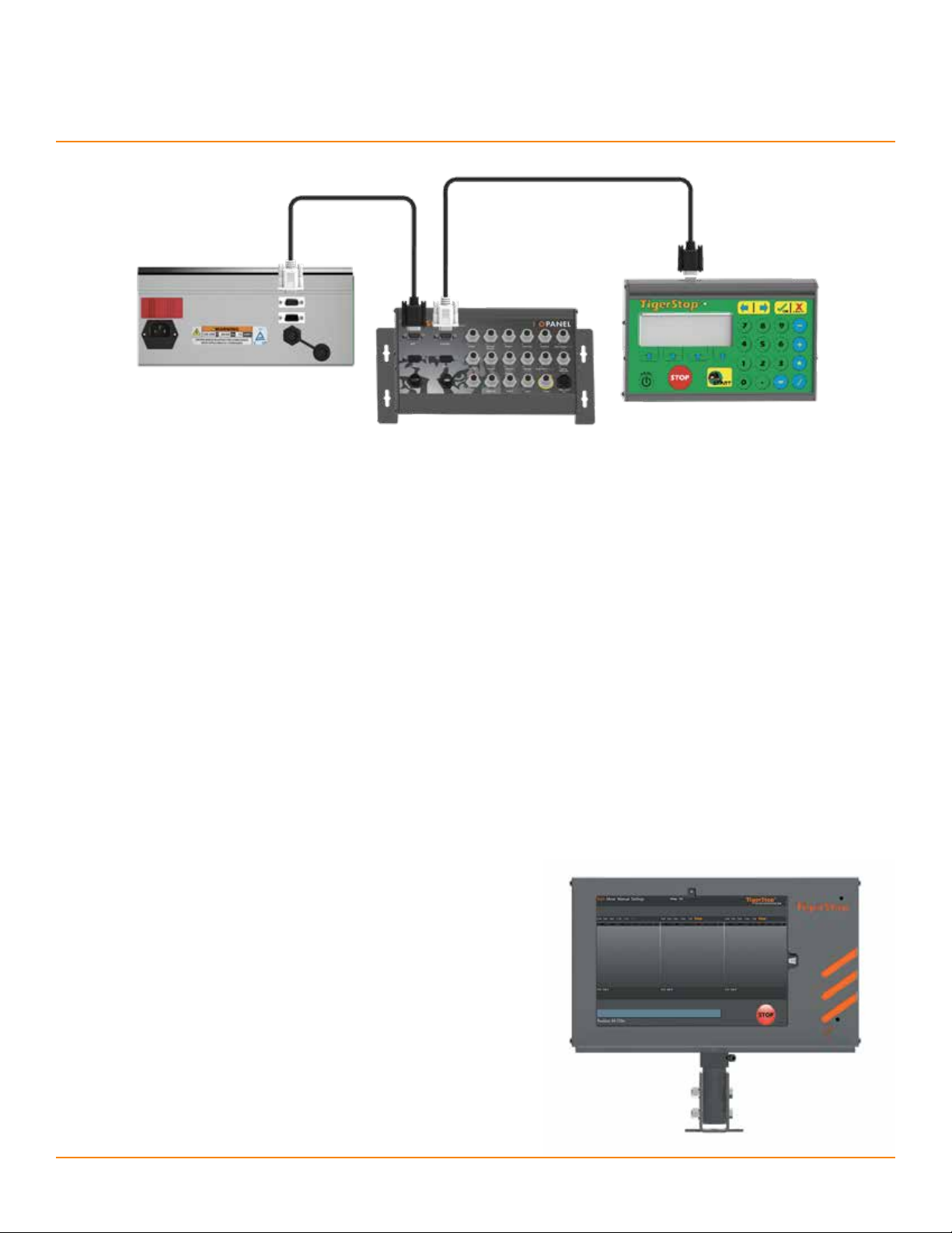
TigerStop Controls
The mitering motion and the pushing motion on a TigerSaw Miter have very similar control electronics (above).
Throughout this manual, these components will be referred to as (from left to right):
• Amplifier
• I/O Panel
• Controller
The amplifier, on the left, provides power to drive the motor.
The controller, on the right, allows the operator to control the machine.
The I/O panel, center, provides ports to support additional components.
• The mitering motion does not require an I/O panel. The mitering controller is connected directly to the amplifier.
Controller cables connect the amplifier to the I/O panel and controller.
• The direction of the controller cables, indicated by the color of the plugs, is important.
• If a cable has blue and yellow plugs, the yellow plug is equivalent to the pictured black plug.
The tablet package (below) controls both pushing and mitering motions.
3
Saw Operation
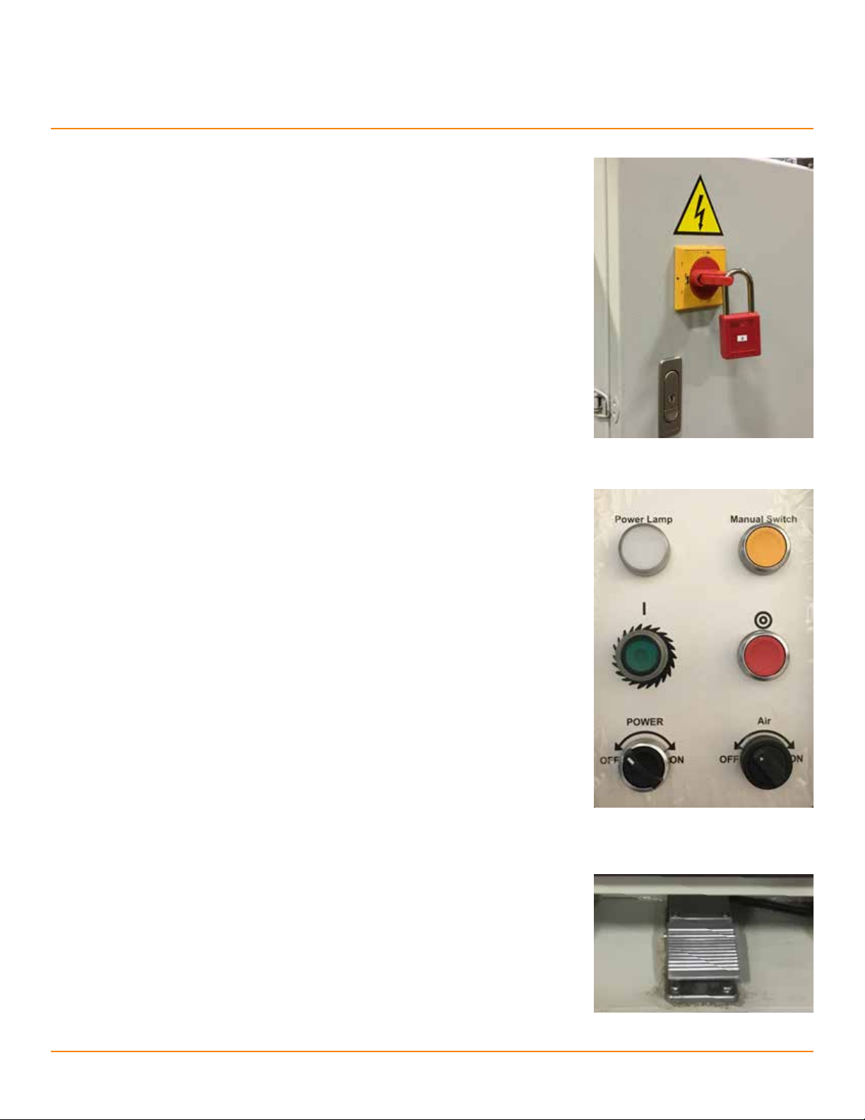
System Power
Power into the TigerSaw Miter system is turned on and o with the large red rotary
switch on the power cabinet, located at the right rear corner of the saw base. In the
o position, this switch folds out and can be locked into place for lockout/tagout
procedures.
Saw Control Panel
This panel, located on the front left corner of the saw base, allows direct control of
basic saw functions.
The power switch, on the bottom left, toggles power to the saw control circuitry. The
power lamp, in the upper left, shows when power is on.
The green button turns the saw motor on, spinning the blade. The green button will
glow while the saw motor is active.
The red button turns the saw motor o.
• The blade will continue spinning for some time after the motor has been turned o.
The yellow button starts a saw cycle.
During a saw cycle:
The top cap fires.
The saw strokes and returns to the base.
The top cap releases.
• The pusher position and the miter angle cannot be changed while the saw cycles.
A saw cycle can also be triggered by the foot pedal on the front of the saw base (right)
or within an automated list in the TigerTouch software (pg. 22).
4
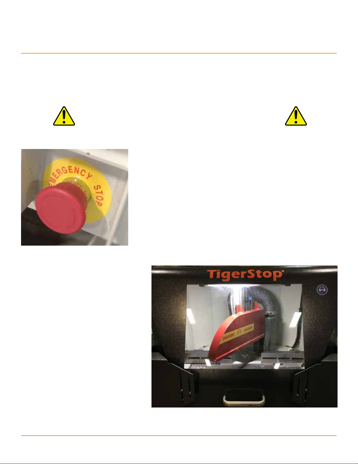
Access Doors and Safety Switches
There are three access doors on the TigerSaw Miter.
Each access door is equipped with a separate safety switch.
Warning: DO NOT disable or bypass the safety switches.
Replace failed safety switches immediately.
Emergency Stop Switch
The emergency stop (E-stop) switch is located on the front of the cabinet,
just below the handle for the tabletop guard door.
Pressing the E-stop switch will immediately stop the saw motor, retract the
blade, and release the top cap.
Before operation can begin again, the E-stop condition must be released by
rotating the switch clockwise.
Saw Operation
Tabletop Guard Door
The tabletop guard door opens upward with the
pictured handle, allowing routine access to the
work area for regular cleaning and for adjusting
material if necessary.
The safety switch on the tabletop guard door
stops the saw motor and the saw stroke when
the tabletop guard door is opened. This switch
also prevents activation of the saw motor until the
tabletop guard door is closed again.
• The blade will continue spinning in the
cabinet base for some time after the motor
stops.
5
Saw Operation
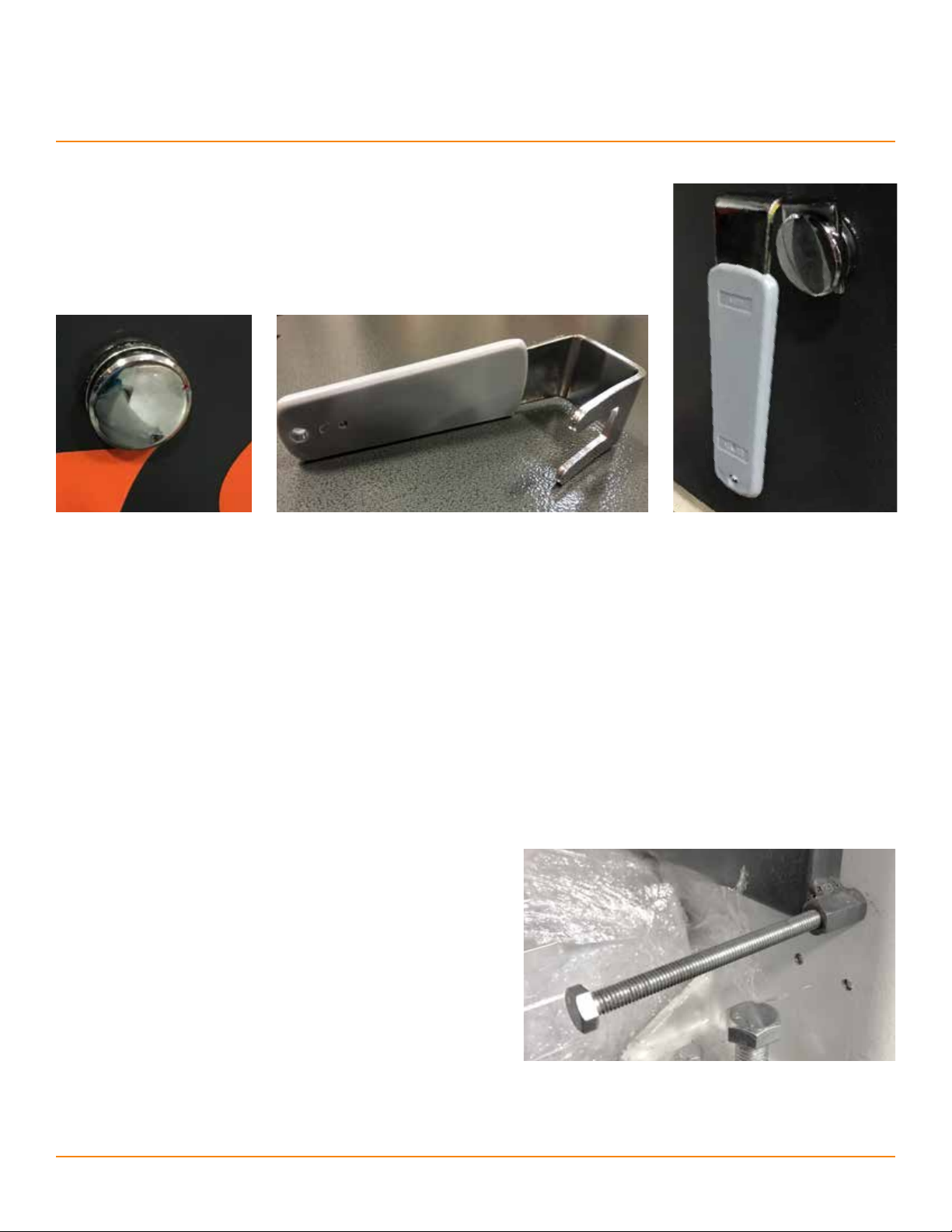
Cabinet Base Doors
The cabinet base doors should only be opened for maintenance.
To prevent operator access, the handle can be removed from the knob.
Front Cabinet Base Door
The front cabinet base door is secured by a safety switch that doubles as a latch. The latch prevents the front cabinet base
door from opening while the saw is spinning. The switch prevents activation of the saw motor until the front cabinet base
door is closed again.
To release the front cabinet base door safety latch:
1. Stop the blade.
2. Leave cabinet power on.
3. Wait sixty seconds.
4. The door can now be opened.
Side Cabinet Base Door
The side cabinet base door is secured by a long access bolt.
The bolt actuates a safety switch when loosened, stopping the saw
motor and the saw stroke. The saw motor cannot be activated until
the access bolt is tightened again.
Do not use a power tool to loosen the bolt faster; the delay allows
time for the blade to stop moving.
6
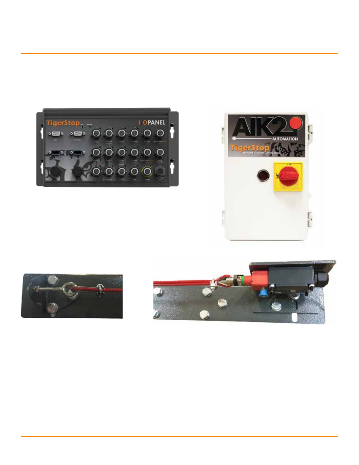
Integration & Automation
The TigerSaw Miter uses TigerStop’s advanced interconnect kit (AIK2) to allow combined control of the positioner and the saw.
This allows a greater degree of automation, with benefits to safety and productivity.
Components
Signaling for the AIK2 is routed through the I/O panel (above).
The safety box (right) monitors safety signals and cuts power to the saw
and the positioner when those signals are disrupted.
The kill line (below) is a red cable stretching the entire length of the saw
system, including tables. The kill line switch (below, right) opens a circuit
when the kill line cable is pulled. This provides an additional way to cut
power to the system in an emergency.
Breaking the Safety Chain
The safety chain is a pair of circuits connected to the emergency switches. Triggering any emergency switch opens both
circuits, signaling a relay to quickly cut power to the positioner and the blade.
In an emergency, there are two ways to break the safety chain:
1. Push the red E-stop button on the front of the saw (pg. 5).
2. Pull the red kill line cable from any position in front of the saw system.
It will not be possible to activate the positioner or the saw blade until the safety chain has been reset.
7

Integration & Automation
Resetting the Safety Chain
There are two steps to reset the safety chain:
1. Rotate the E-stop button on the saw (pg. 5) clockwise
until it pops out.
2. Pull the blue knob of the kill line switch. It should click into
place.
• If the blue knob won’t lock into place, adjust the kill line tension
(pg. 29).
The safety chain is now active, allowing the system to be powered up.
The state of the safety chain is indicated by four LEDs on the safety
relay, visible through the circular window on the safety box (right).
From top to bottom:
• Power into the safety relay
• Power across the safety relay
• Safety chain circuit 1
• Safety chain circuit 2
Interconnect Behavior
The AIK2 can behave in multiple ways. These options can be selected with the TIK (Tool Interconnect Kit) setting (pg. 19).
There are three options:
1. Full Auto: Both cutting and positioning are automated.
• This is the standard setting for the TigerSaw Miter.
• The operator selects a pusher list, loads stock, and starts the process.
• The system automatically pushes and cuts until the entire stock piece is processed.
• The operator loads the next stock piece.
2. Advanced: Only positioning is automated.
• The operator selects a pusher list, loads stock, and starts the process.
• The system automatically positions the stock for the next cut.
• The operator cycles the saw.
• The previous two steps repeat until the entire stock piece is processed.
• The operator loads the next stock piece.
3. None: Every motion is initiated by the operator.
8
Basic TigerStop Operation
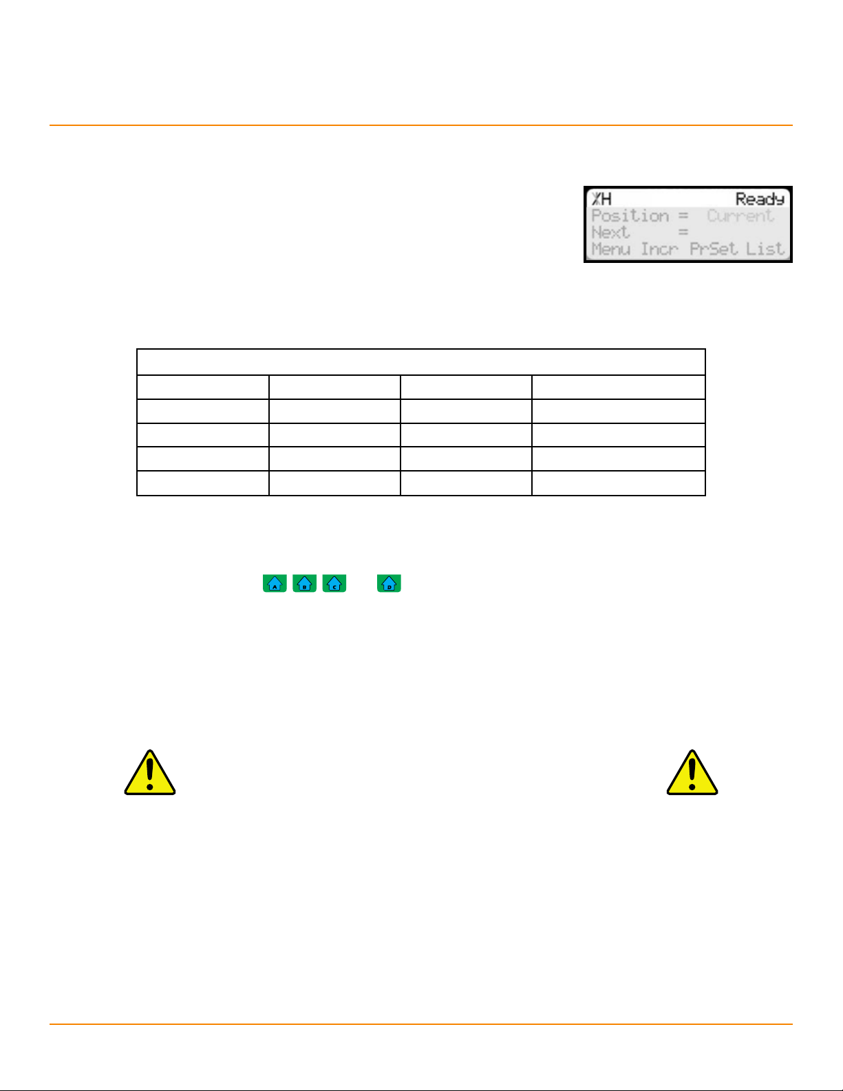
Controller Display
The top line on the controller display always contains information about the current status
of the electronics.
• The heartbeat, in the upper left, is a rotating line indicating normal function.
The heartbeat stops during data entry.
• The letter next to the heartbeat is the drive indicator, which shows the motor
status. Use the table below to interpret the drive indicator.
• The name of the displayed screen is shown in the upper right.
Drive Indicator
H
A
C
D
L
Holding Still
Accelerating
Constant Speed
Decelerating
Lash
W
X
N
S
J
Communication Error
Waiting
Drive Disabled
Stopping
Jog
Soft Keys
The buttons underneath the display (
The soft keys have dierent functions at dierent times. The current functions of each soft key are indicated by soft key prompts
on the bottom line of the display.
, , , and ) are known as soft keys.
Home Routine
After initializing, each controller will read, “Clear the Deck. Press START to run the Home Routine”.
Warning: During the home routine, the machine will move.
Be sure the path is clear to prevent collisions.
The home routine is a reference routine that must be successfully completed before the motor will respond to commands.
• The home routine can also be run at any time from the Setup menu (pg. 15).
During the home routine, the positioner will move slowly to the sensor at the maximum position.
• Positive miter angles point the blade toward the outfeed.
When the home routine is finished, the controller will display the Ready Screen (pg. 10).
9
Basic TigerStop Operation
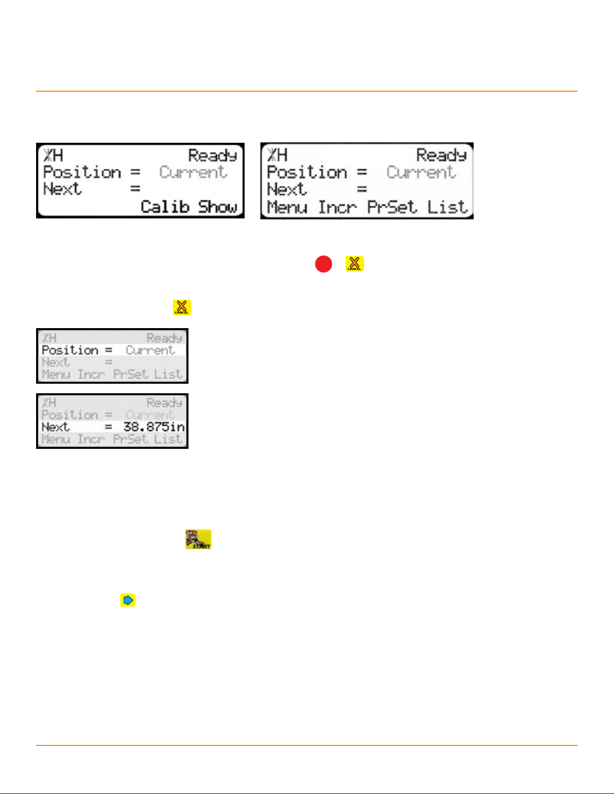
Ready Screen
The Ready Screen (above) is the starting point for all TigerStop functions.
The Ready Screen can always be reached by repeatedly pressing
The Ready Screen has two forms (above). From the basic Ready Screen (left), press the [Show] soft key to display the
expanded options (right). Press
to return to the basic Ready Screen.
Line 2 of the Ready Screen shows the current position.
• The position on the controller for the linear positioner can be set to display units
of inches (in) or millimeters (mm) (pg. 19).
• The position on the miter controller will display the angle in degrees (°).
Line 3 of the Ready Screen is the target position for the next movement. User input will
also appear in line 3.
38.875 inches is 987.4 mm.
STOP
or .
Manual Movement
Manual movements are initiated from the Ready Screen.
Enter the target position and press
• If the target position is a whole number, there is no need to enter the decimal.
• If the target position is negative, it must be entered using calculator mode (pg. 11).
• If units are set to inches, then it is also possible to enter the target position as a fraction. Enter the number of whole
inches, the
• Positive miter angles point the blade toward the outfeed.
button, and then the fraction.
to begin moving.
10
 Loading...