

Page 1
E2 / 2009 ESC 4.1
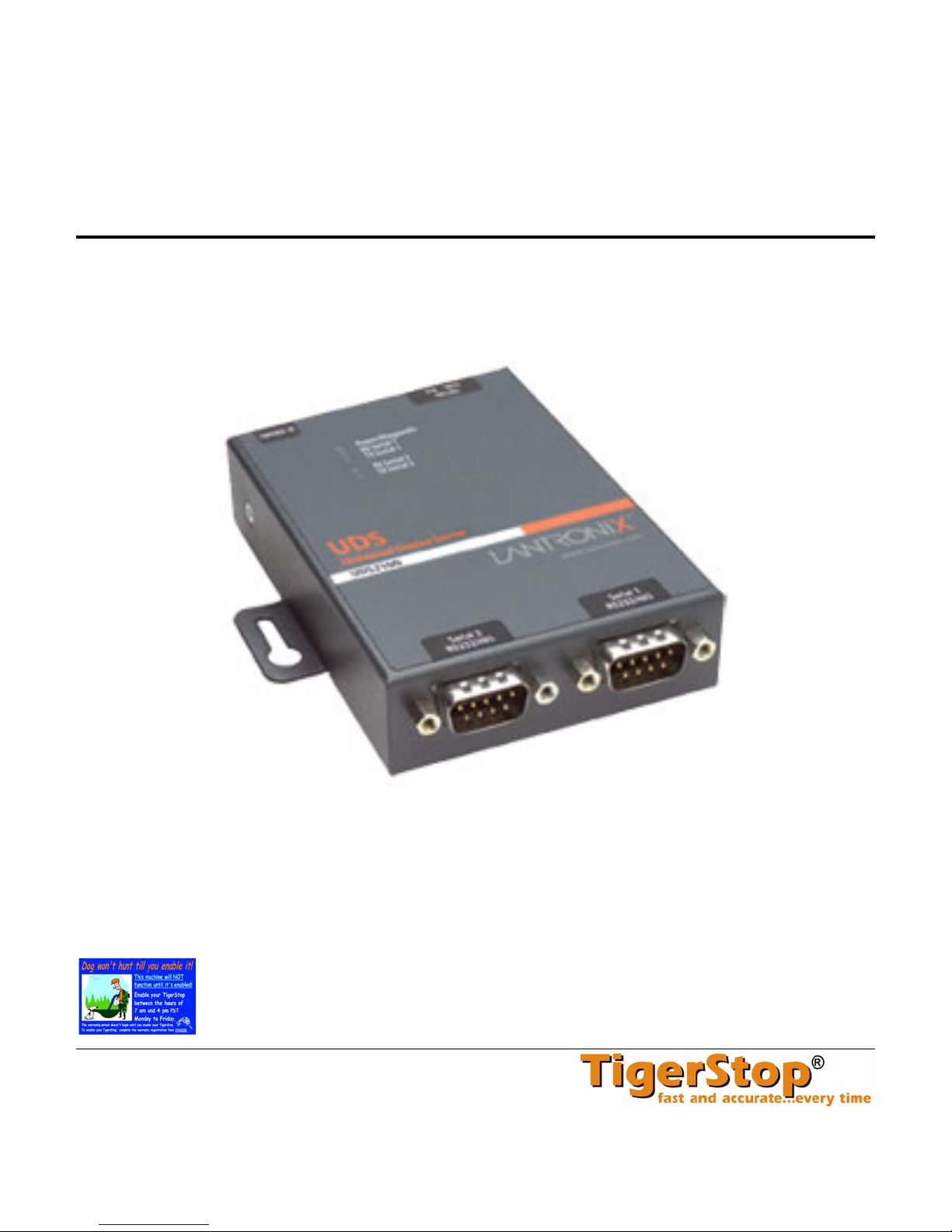
TigerStop® Ethernet-to-Serial Converter
Installation & User’s Guide v4.1
June 2009 TigerStop Version 5.03+
CONTACT:
TigerStop LLC, Assembly Plant, 12909 NE 95
© 2009 TigerStop LLC
th
St., Vancouver, WA 98682 U.S.A.
Page 2

Page 3
Ethernet to Serial Converter
Description and Use
The ESC is an Ethernet-RS232 adapter that lets
you plug TigerStop into an ethernet network,
eliminating the need for a serial port on your
computer or a short haul modem, and permitting
communication with TigerStop across your
network.
Fig. 1
System Specification
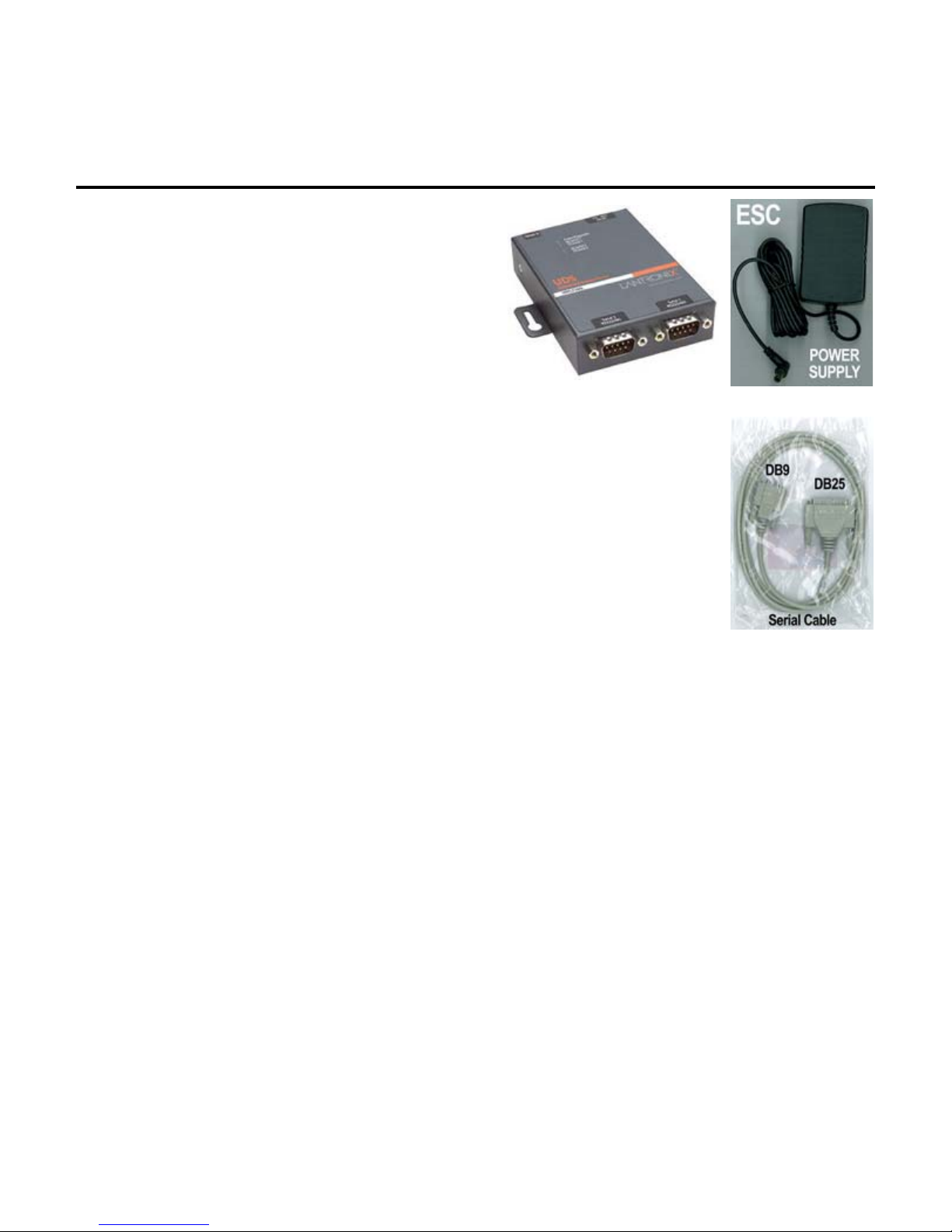
The ESC consists of the adapter (Fig. 1) and its power cord (Fig. 2). The
adapter has two DB25 serial ports, allowing one ESC to connect to two
TigerStops. One serial cable is included (Fig. 3).
The ESC is compatible with…
any Ethernet network
any TigerStop enabled with the TigerSet, Optimizer, or Download
software packages.
Workflow Manager 5.4 (or TigerLink version 5.0 or higher)
The connection to the TigerStop requires a straight-through serial cable with
a male DB25 connector on one end, and a female DB9 connector on the
other end.
The connection to the network requires a standard straight-through CAT5
Ethernet cable with standard RJ45 connectors on each end. This is also
available at any electronics or computer store.
ESC
Fig. 2
Fig. 3
1
Page 4
Installation and Setup
Controller Setup
On the TigerStop side of the installation, the controller has no specific setup requirements, but
the user must know the controller’s baud rate. The default setting is 115200, but this can be
checked or changed in the System Menu.
Access the System Menu
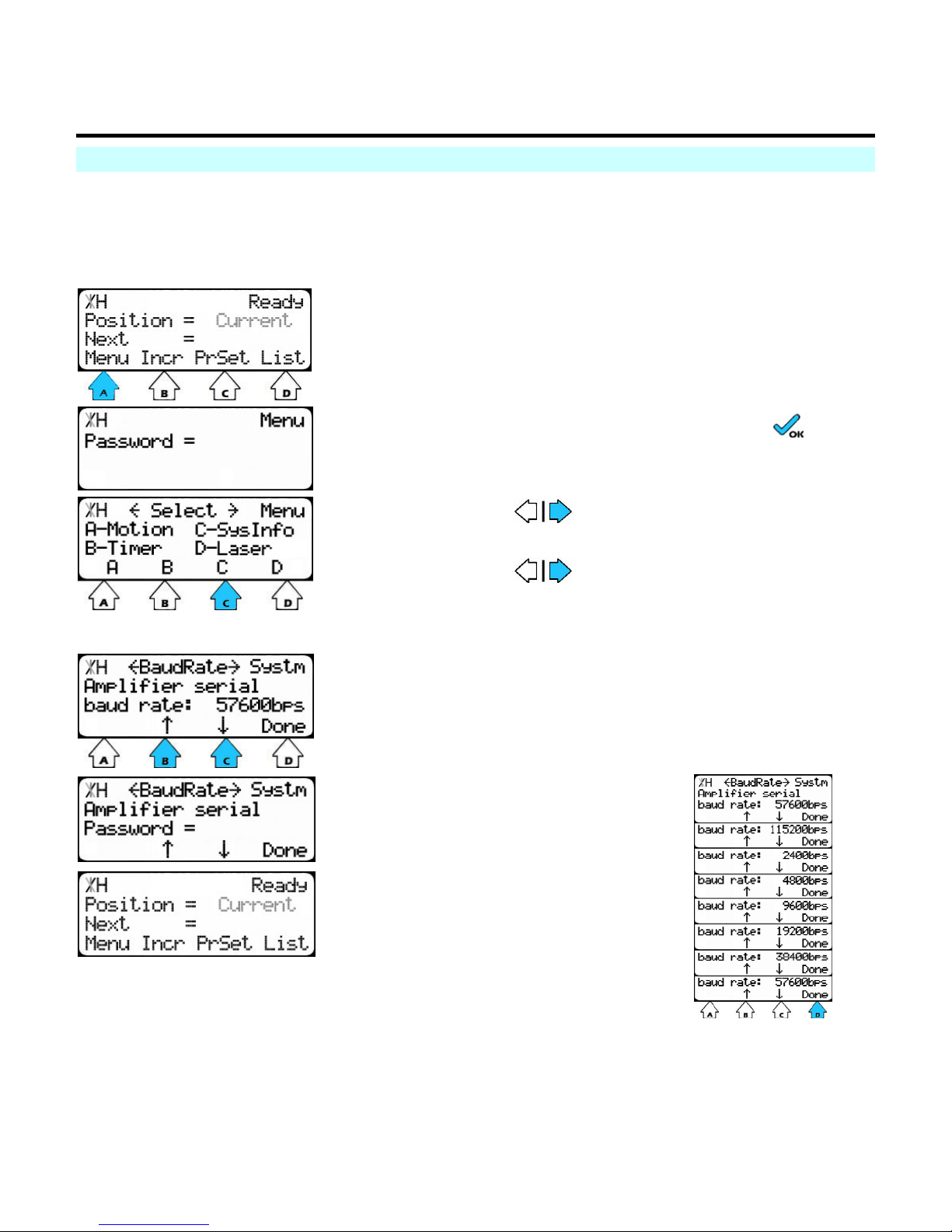
At the Ready Screen…
1. press [A] to select Menu
2. Enter the password and press .
3. for Menu screen 2.
4. press [C] to access System Information
Check or change the baud rate
5. to scroll through the screens of the
system menu until you get to Baud rate.
The current baud rate is displayed at this screen.
1. Press [B] or [C] to trigger password prompt.
Baud rate is a list parameter.
2. Enter the password, and
press [=].
3. Press [B] or [C] to scroll
through the baud rates.
4. Press [D] to save
selection and exit to the
Ready Screen.
2
Page 5
Installation and Setup
Hardware Setup
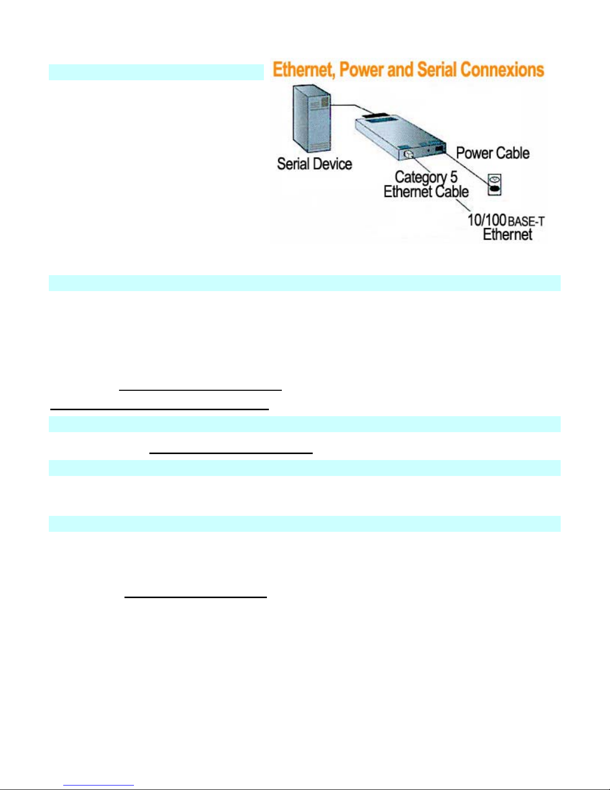
1. Connect a serial device to your
ESC unit with the serial cable
provided.
2. Connect a category 5 ethernet
cable to the RJ45 port.
3. For units provided by TigerStop,
use the power supply that is
included in the packaging.
Note
The required input voltage is 9-30 VDC
(center +) or 9-24 VAC (1.5W maximum
power required).
Software Setup
This is done through the Ethernet Device Installer.
The ESC comes with a default IP of 0.0.0.0, which sets it to DHCP.
It is also possible to change the device’s settings if the IP address is known by typing that
address into the address bar of a web browser and using the Java utility found there. Don’t
forget to click Update Settings to affect any changes desired.
Install the Ethernet Device Installer
Run the Ethernet Device Installer
Computer Setup
Install and run The Ethernet Re-director
Maintenance
The ESC should never need any maintenance. If a problem does develop, pulling out the power
cord for 10 seconds should resolve it.
Use
Ensure that the re-director service is functioning, then connect to the virtual port normally (Hyper
Term, Workflow Manager, custom program, etc). Everything should happen normally after this
point.
See also… ESC Troubleshooting
3
Page 6
Ethernet Device Installer
To use the ESC Ethernet-to-Serial Converter, some software on
the accompanying CD must first be installed and run on your
computer.
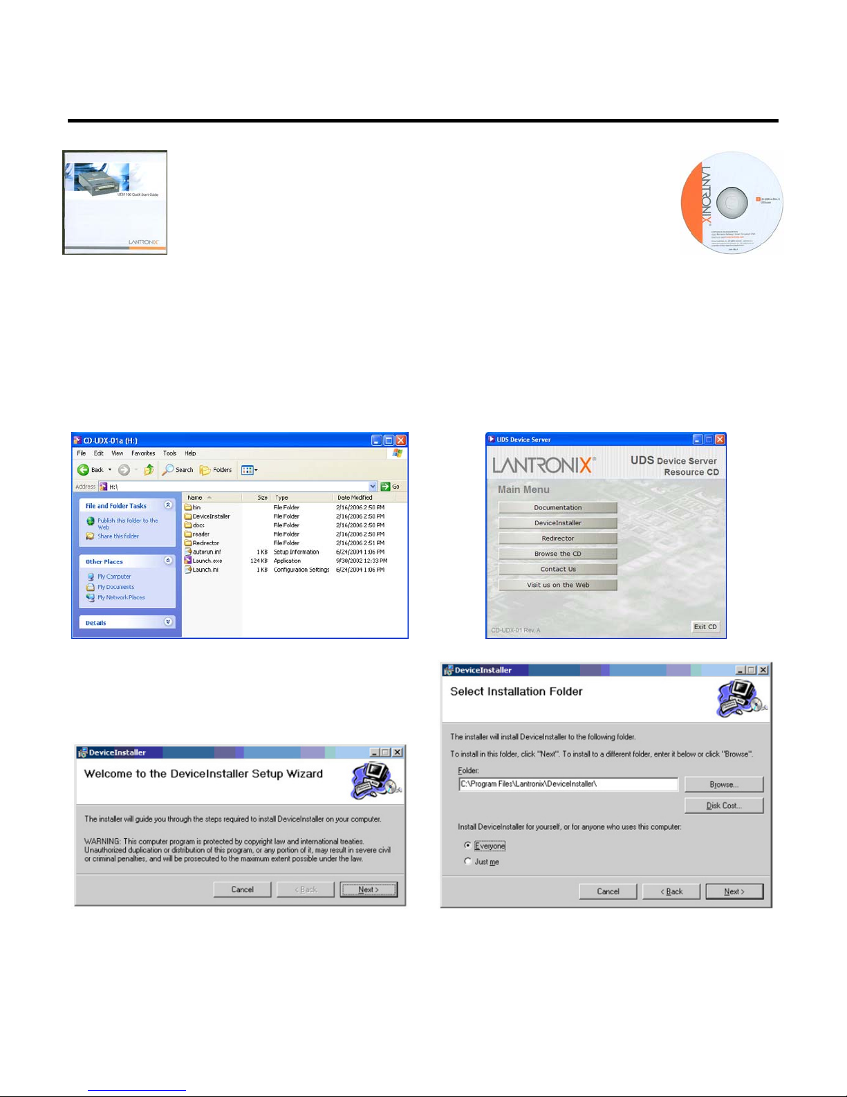
The ESC comes with a Quick Start Guide from Lantronix (Fig. 1)
and a CD (Fig. 2). Everything you need to know about the
Ethernet-to-Serial Converter can be found in the TigerStop
Fig. 1
Manual. The Lantronix guide is for additional reference.
Insert the CD into your CD-ROM drive.
If the CD launches automatically, continue at the Setup Wizard (Fig. 5). If the CD does not launch
automatically…
1. Click the START button on your computer task bar, and click Run.
2. Click Browse and select the CD-ROM drive. The Browse screen (Fig. 3) displays.
3. Click Launch.exe. The UDS Device Server window (Fig. 4) displays.
Fig. 2
Fig. 3
Fig. 4
Fig. 5
Fig. 6
4. Click Device Installer button. The Device Installer Setup Wizard (Fig. 5) displays.
5. Click Next. The wizard creates a folder (Fig. 6) in which to install Device Installer.
6. Set permissions to "Everyone." You can browse for a different folder, or set the permissions
4
Page 7

to "Just me," according to your preference. Click Next.
7. The Installation Complete screen displays last. Click Close to exit.
Ethernet Device Installer
5
Page 8
Run the Ethernet Device Installer
Assign the IP Address
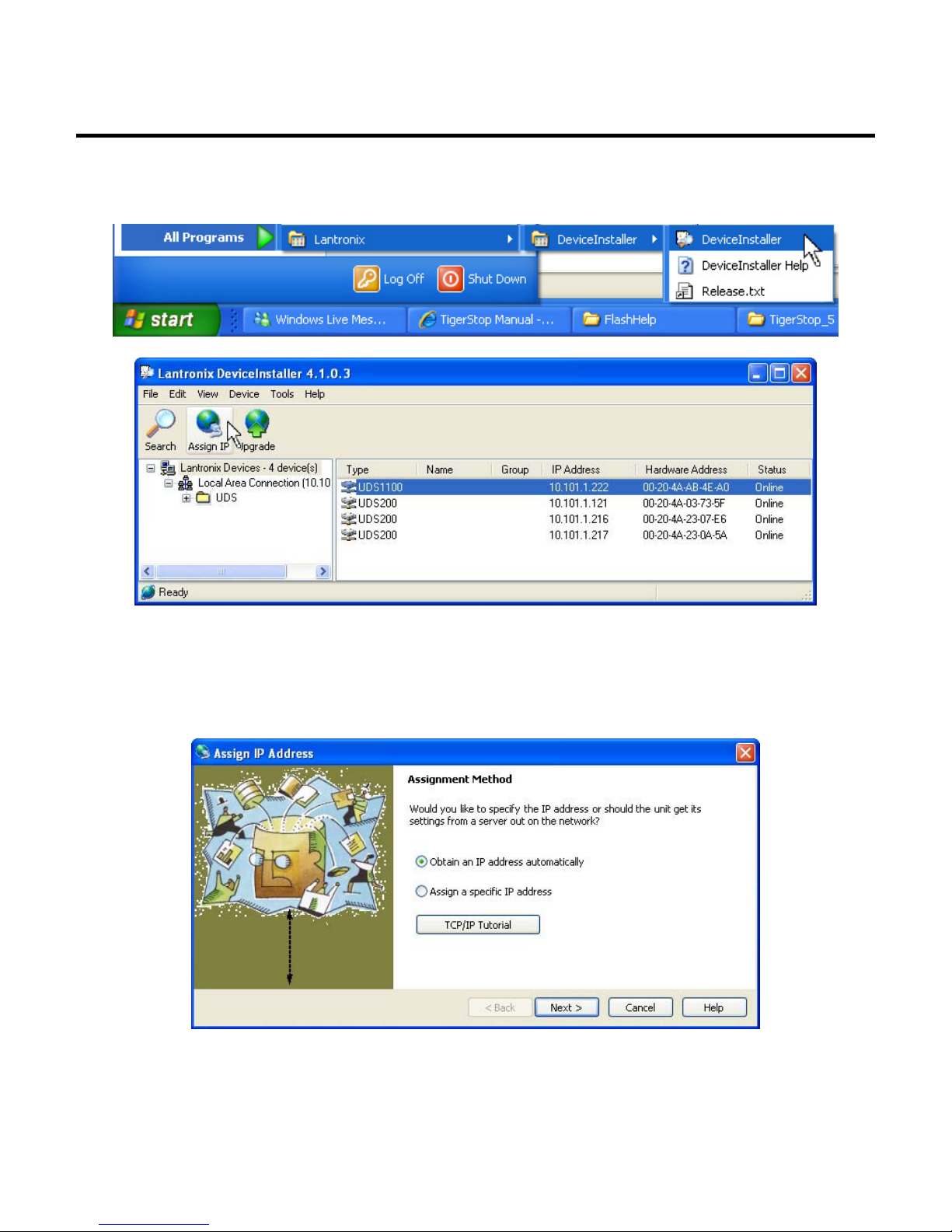
1. Click the START button on the task bar and select All Programs > Lantronix >
DeviceInstaller > DeviceInstaller (Fig. 1).
Fig. 1
Fig. 2
2. The Device Installer window (Fig. 2) appears, displaying in the left pane a directory tree
and in the right pane all the UDS devices on the network. Select a UDS device and click
Assign IP. If you click Assign IP without selecting a UDS device, a screen will display
asking for device identification. When you enter a hardware address at this screen, the
Assign IP Address screen displays next (Fig. 3).
Fig. 3
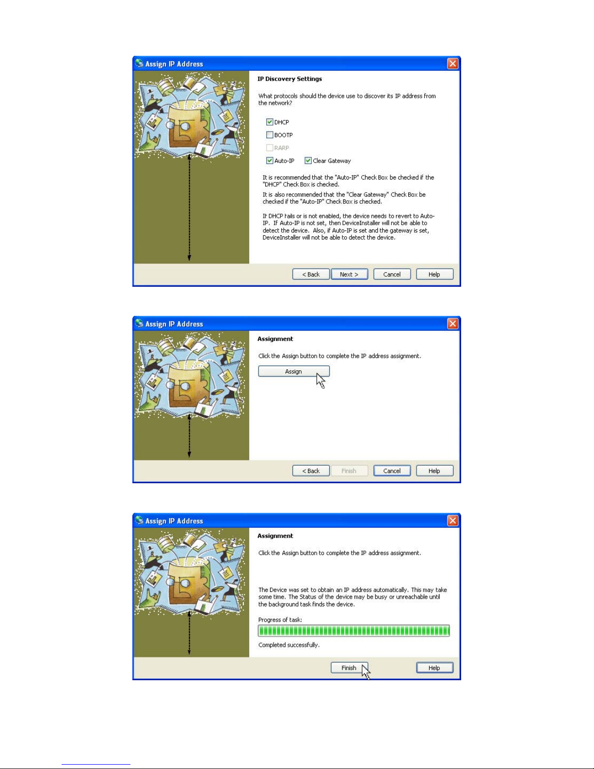
3. Select "Obtain an IP address automatically" (Fig. 3) and click Next. The IP Discovery
Settings screen (Fig. 4) displays. The default setting values are only examples. If you are
unsure about these values, contact your company's system administrator.
6
Page 9
Run the Ethernet Device Installer
Fig. 4
4. Adjust the selections (Fig. 4), if necessary and click Next.
5. Click Assign (Fig. 5) to complete the IP address assignment.
6. When the task shows as Completed successfully, click Finish (Fig. 6) to exit.
Fig. 5
Fig. 6
7
Page 10

ESC Installation & User's Guide
Appendix: IP Addressing
IP addresses are classified as Class A, B and C, and the ranges are:
Class A = 1.0.0.0 ~ 126.0.0.0
Class B = 128.0.0.0 ~ 191.255.0.0
Class C = 192.0.1.0 ~ 223.255.255.0
Reserved address ranges for private (non-routed) use:
10.0.0.0 ~ 10.255.255.255
172.16.0.0 ~ 172.31.255.255
192.168.0.0 ~ 192.168.255.255
Other reserved addresses:
127.0.0.0 is reserved for loopback and IPC on the local host.
224.0.0.0 ~ 239.255.255.255 are reserved for multicast addresses.
8
Page 11

Configure the Ethernet Adaptor
1. Click the START button on the task bar and select All Programs > Lantronix >
DeviceInstaller > DeviceInstaller (Fig. 1).
Fig. 1
Fig. 2
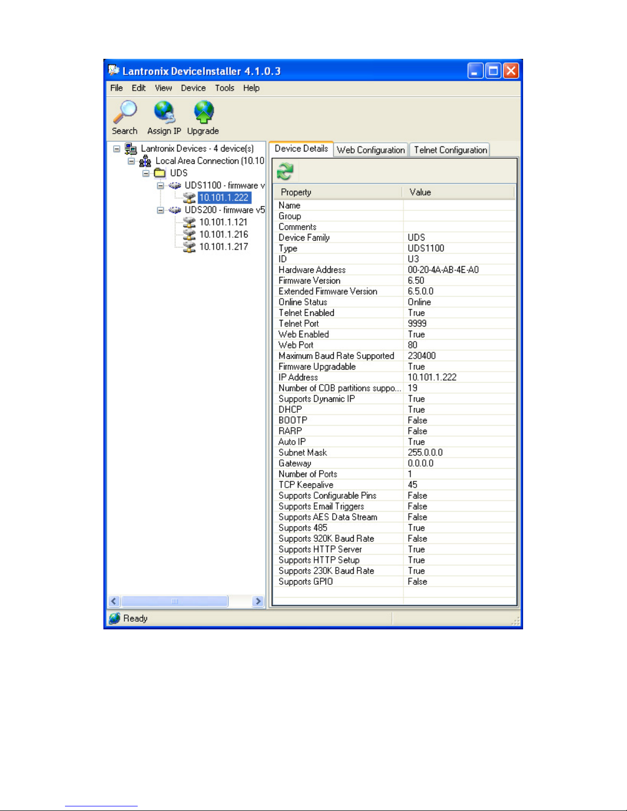
2. Double click on a UDS to open a window with 3 tabs: Device Details, Web Configuration
and Telnet Configuration (Fig. 3).
9
Page 12
ESC Installation & User's Guide
3. Click Edit Settings. The Port Properties screen (Fig. 4) displays.
10
Fig. 3
Page 13

Configure the Ethernet Adaptor
Fig. 4
4. Click the Advanced tab. The Advanced tab (Figs. 5-6) displays all the port properties in
detail.
Fig. 5
11
Page 14
ESC Installation & User's Guide
Fig. 6
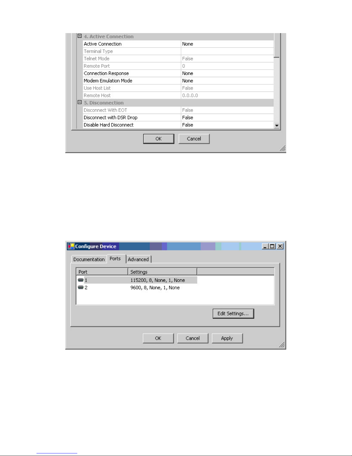
5. In the 1. Serial Settings (Fig. 12) parameters, change Baud Rate to 115,200 as shown in
the example, or to whatever baud rate is set in the controller.
6. In the 3. Passive Connection (Fig. 12) parameters, change Local Port to 14001, and click
OK.
The Local Port needs to be 11000 higher than the port setting in the Redirector. The other
Advanced settings should be left at their factory defaults.
If you will use two Local Ports, go back to step 2, Configure, and set up the second port the
same way. When you are back at step 6, change the Local Port to 14002.
The Configure Device screen (Fig. 7) reappears.
7. Click Apply. The program should now update the settings and reboot the device.
When in use, both ports should have a baud rate matching the controller baud setting, 115200. (The factory
default is 9600.) Also be sure that Data bits = 8, Parity = None, Stop bits = 1, Flow control = none. (These should
be the factory default settings.)
12
Fig. 7
Page 15

The Ethernet Redirector
Install the Ethernet Redirector from the CD
Insert the CD into your CD-ROM drive. When the UDS
Device Server window displays, click Redirector to install it.
Redirector Setup prepares the Install Shield Wizard and
flashes a logo on screen momentarily.
Lantronix Redirector Install Shield Wizard opens.
Click Next.
Install Shield Wizard opens.
Click Next.
13
Page 16
ESC Installation & User's Guide
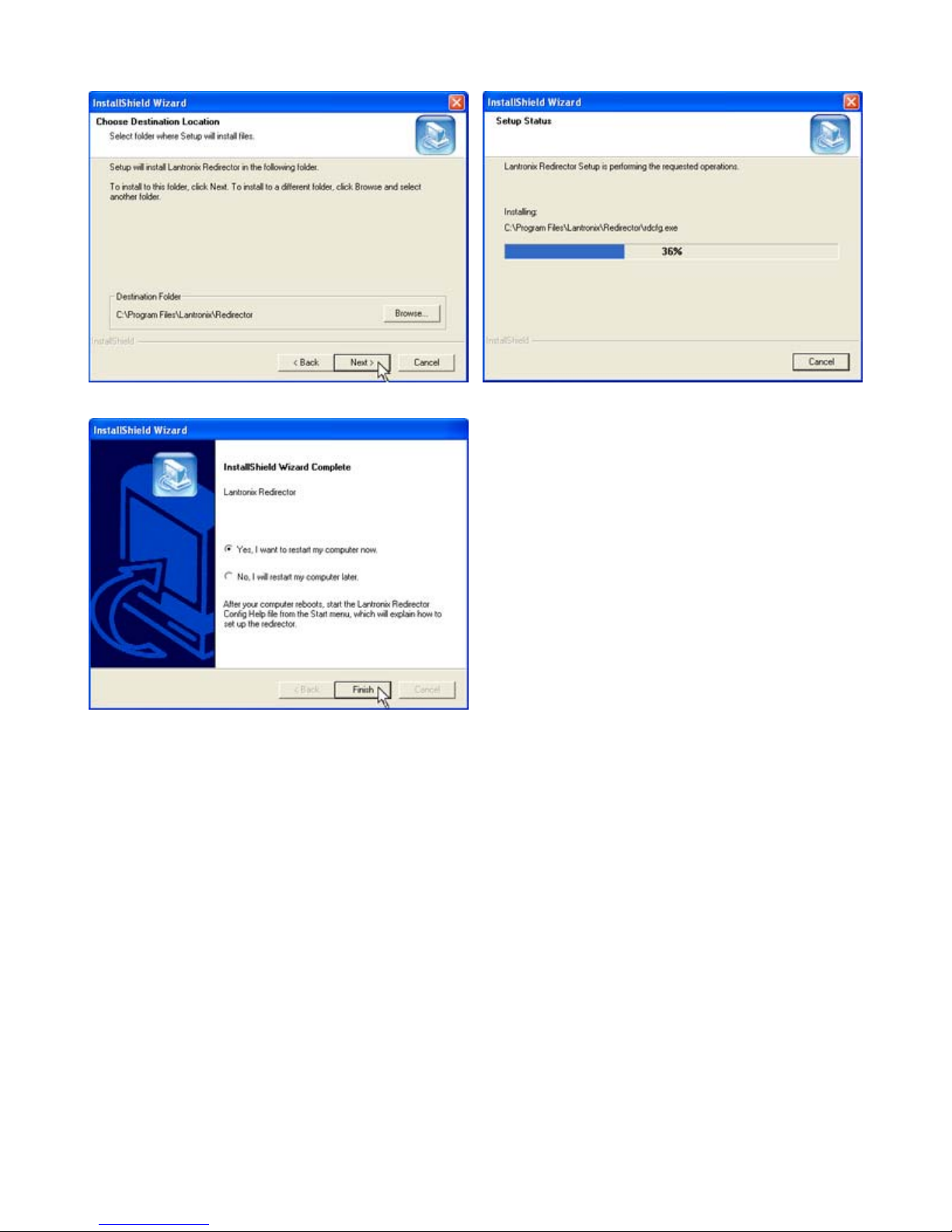
Choose destination for Redirector, either the default, or
browse and create your own. When finished, click Next.
When installation is complete, select either Yes restart
computer now, or No restart computer later, and click Finish.
The computer must be rebooted to use the Redirector.
Install Shield Wizard installs the Redirector.
14
Page 17
Launch the Redirector
Start the Redirector
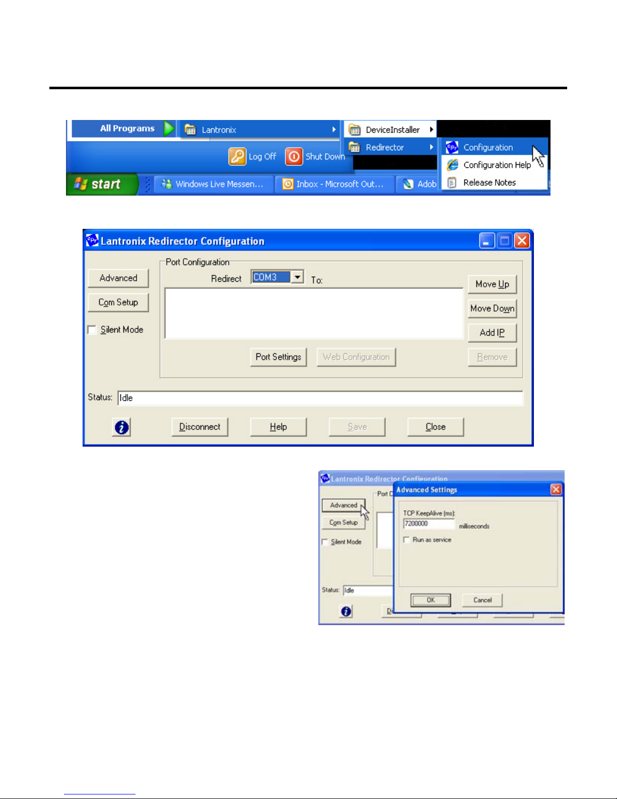
Click the START button on the task bar and select All Programs > Lantronix > Redirector
> Configuration. The Lantronix Redirector Configuration screen (Fig. 1) will display.
Fig. 1 - Redirector Configuration screen
Redirector Configuration buttons:
1. Advanced - Sets time out, run as service
2. Com Setup - Selects available com ports
3. Port Settings - Sets various port parameters
4. Move Up - sorts IP address UP in the window
5. Move Down - sorts IP address DOWN in the window
6. Add IP - Adds host and TCP Port
7. Disconnect - Ends session and disconnects
8. Help - Opens a web help file from Lantronix
Fig. 2 - The Advanced button dialog box.
15
Page 18
ESC Installation & User's Guide
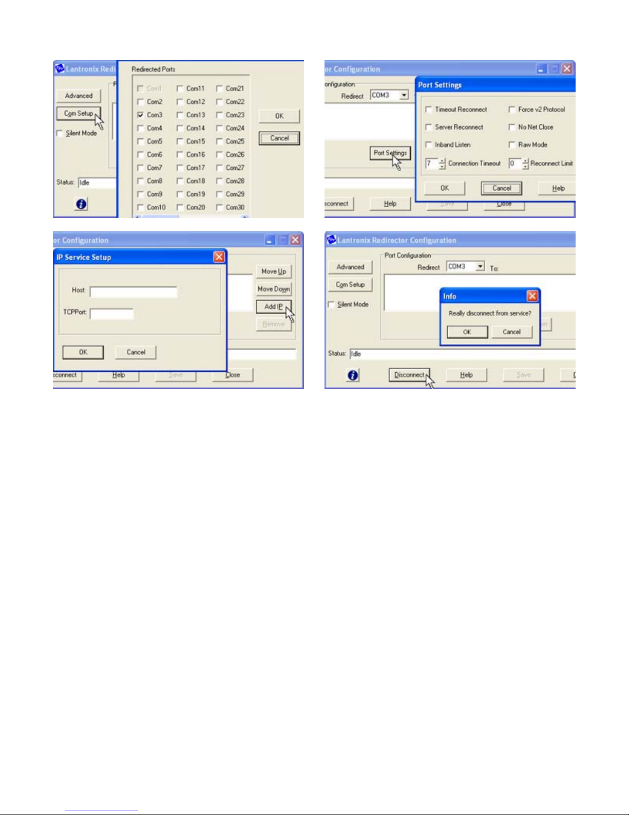
Fig. 3 - The Com Setup button dialog box.
Fig. 5 - The Add IP button dialog box.
Fig. 4 - The Port Settings button dialog box.
Fig. 6 - The Disconnect button dialog box.
Open the Com Port Redirector and set up the virtual com ports.
1. Click the Com Setup button (Fig. 3).
2. Check the box next to the first two Com labels. This is usually Com3 and Com4, so the
remainder of this guide will assume it is. This enables port redirection for these com
numbers.
3. Select COM3 from the top-center “Redirect To” drop down menu (Fig. 1).
4. Click the Add IP button (Fig. 5).
5. Enter the IP address of the first ESC in the Host box (Fig. 5, pop up).
6. Enter 3001 in the TCP port box (11000 less than the number entered for Channel 1 in the
ESC setup).
7. Click OK.
8. Click Save.
9. Select COM4 from the top-center “Redirect To” drop down menu.
10. Click the Add IP button.
11. Enter the IP address of the second ESC in the Host box.
12. Enter 3002 in the TCP port box (11000 less than the number entered for Channel 2 in the
USD1100’s setup).
13. Click OK.
14. Click Save (Fig. 1) and Close.
15. Restart the computer.
16
Page 19

ESC Troubleshooting
ESC TroubleshootingFollow these steps in case of a communications
failure:
1. Confirm hardware connections
2. Confirm software settings
3. Contact TigerStop Customer Support
Confirm Hardware Connections
The first step in troubleshooting almost any type of technical failure is to check the physical
connections. Turn the power off, then trace the path of communication from one end to the
other and ensure that everything is securely in place. This is usually accomplished by
unplugging, then re-plugging, each end of each cable. In this case, the critical cables to check
are:
Serial cable connecting the TigerStop controller to the adapter box.
Ethernet cable connecting the adapter box to the network.
Power cable for the adapter box.
Confirm Software Settings
Review setup procedure in the topic Run Ethernet Device Installer to view the software settings
and correct them if necessary.
Contact TigerS top Customer Support
If you are not successful in correcting the problem, contact TigerStop Customer Service. Our
service technicians are available during regular business hours at our assembly plant in
Vancouver, WA, U.S.A. All incoming service calls and/or email are acknowledged, and most
challenges are resolved, within the same business day.
17
 Loading...