

Page 1

OBSTACLE
FRONT
AGES 12 & UP
RIGHTLEFT
DARK BRIGHT
A division of Hasbro, Inc.
Where Technology Comes to Play!
TIGER name and logo and package design
®, TM, & © 2001 Tiger Electronics. All rights reserved.
980 Woodlands Parkway, Vernon Hills, IL 60061, U.S.A.
www.tigertoys.com
™
MADE AND PRINTED IN CHINA
ON
or
OFF
Item No. 70709
TM, © 2000 Bandai. WonderBorg, Robotworks and
all related logos, names and distinctive likenesses
thereof are the property of Bandai.
200105710IWTI-01
Page 2

INTRODUCTION CONTENTS
A word from Tiger Electronics
Thank you for buying the WonderBorg. Please read this instruction manual
carefully before using your Wonderborg, and always use the product as
directed. We also recommend that you keep this instruction manual in
a safe place.
What is the WonderBorg?
The WonderBorg is a robot kit developed especially to let you experience
the fun of creation. It’s easy and fun to assemble the WonderBorg,
even if you have no special knowledge of programming or mechanical
engineering. Let the WonderBorg introduce you to the wonderful world
of robots!
Caution
Be sure to read this
- Please be sure to read this instruction manual thoroughly before
operating the WonderBorg.
Notes on Handling:
- Do not touch the terminals or allow them to get wet or dirty,
as this could cause the product to malfunction.
- This product is a piece of precision machinery. Do not use or
store it in extreme temperatures, or subject it to severe shocks.
Under no circumstances should the electronic parts in this product
be disassembled.
What is the WonderBorg ------------------------- 3
Hardware: How to Assemble the Robot
Names of Parts --------------------------------- 7
Tools Required and List of Parts --------------- 8
Assembling the Mechanism ----------------------- 10
Installing the Motherboard --------------------- 11
Fitting the Legs ------------------------------- 12
Fitting the Antennae --------------------------- 13
Bending the Legs and Antennae ------------------ 15
Fitting the Body Shells ------------------------ 16
Operational Testing ---------------------------- 16
Hardware Variations:
Advanced Fun with the WonderBorg
Changing the Gears ----------------------------- 17
Assembly Variations ---------------------------- 19
The Option Connector --------------------------- 20
Coloring Variations ---------------------------- 21
Software: How to Use Robot Works
1
Notes on Use:
- This product is comprised of precision electronic parts. It should
not be dropped, allowed to get wet or dirty, or disassembled.
Avoid using or storing this product in environments where the
temperature is very high or very low.
- Inevitably, some of the parts have sharp points and dangerous
edges, so please take care when assembling the product.
- Attempting to operate the WonderBorg using an infrared remote
control device for another appliance such as a TV set may cause
this product to malfunction.
- Malfunctions may occur if the product is placed beside a window
in direct sunlight, directly below a fluorescent light or
other strong light source.
- If a malfunction occurs, switch the power OFF, then ON again.
- Do not place stickers over the transmitter and or the receiver
as this could cause malfunctions.
- If any object gets in the way between the transmitter and receiver,
the product will become unable to sense infrared, and will cease
to function.
- When the batteries run low, malfunctions may occur. In this case,
replace the batteries.
- This product uses reflective sensors, so the infrared sensor
may be unable to function on dark-colored walls and floors.
Please use the product on light-colored walls and floors.
Software --------------------------------------- 22
2
Page 3
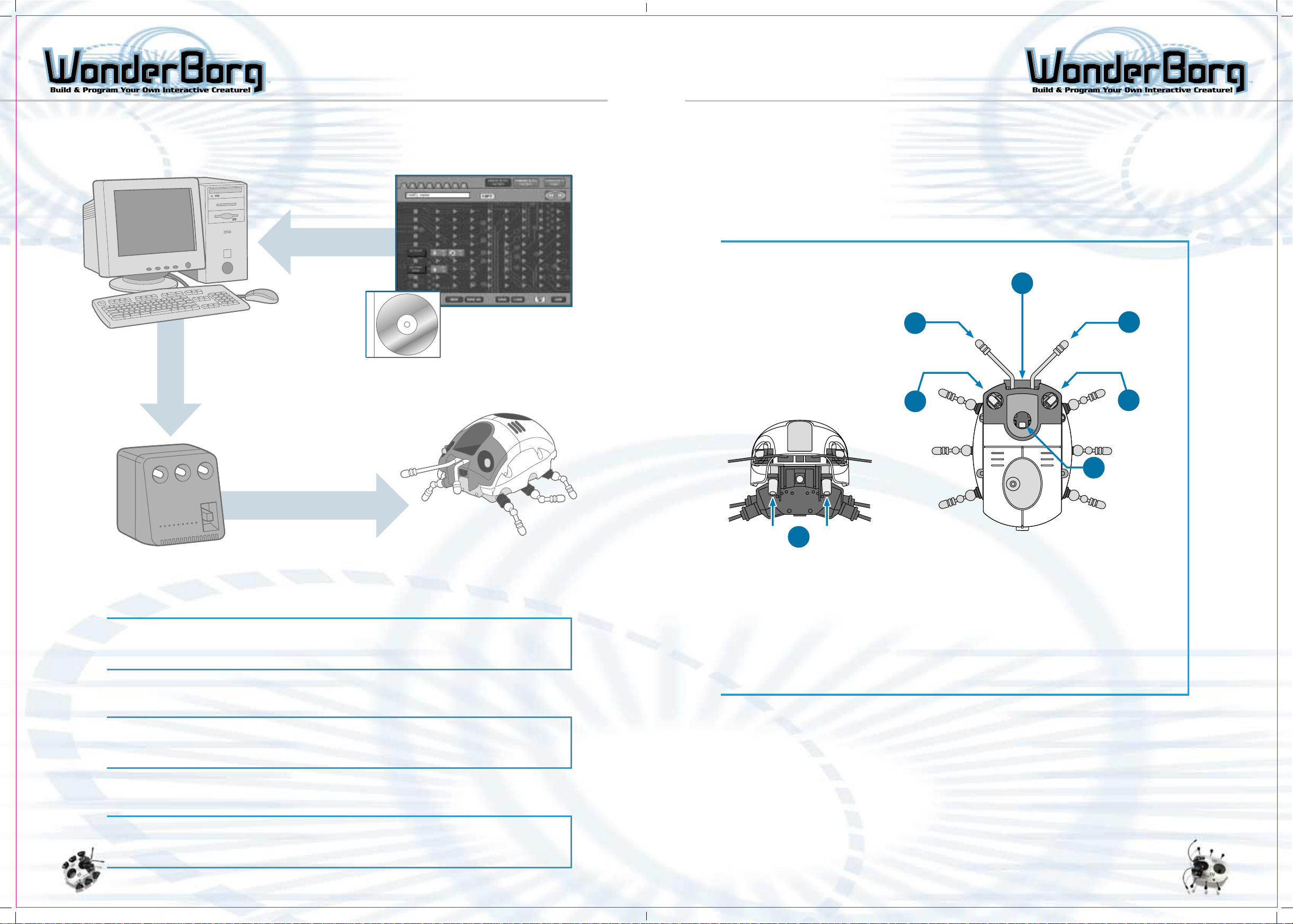
CONFIGURATION OF THE WONDERBORG CONFIGURATION OF THE WONDERBORG
Configuration of the WonderBorg
Download software
onto PC.
Robot Works
Your computer transmits
Program instructions to
the Interface
(WonderBorg’s
Software)
The WonderBorg's Body
The computer determines how the WonderBorg reacts to information perceived by the sensors.
The left and right legs are moved by their respective motors. When the legs on both
sides move forward, the WonderBorg advances. When the legs on the right move forward
and the legs on the left move backward, the WonderBorg turns to the left.
The various sensors are shown below
WonderBorg's Sensors
1
7
6
2
3
The Interface downloads
Program to the WonderBorg
WonderBorg
Interface
WonderBorg
The WonderBorg is a robot you assemble yourself. It has feet that can move backwards/
forwards and right / left, various sensors, and its own built-in computer. Its movements
are controlled by programs you can create on your PC.
Robot Works
Robot Works is the WonderBorg’s own programming software. You install this software
on your computer from the CD-ROM included. By simply lining up blocks on your computer
screen, you can create your own programs for the WonderBorg.
4
5
1. Infrared signal receiver.: Distinguishes infrared signals coming from
the Interface
2. Antenna (right): A sensor in the antenna socket enables the robot to react
when the antenna touches something
3. Infrared LED (right): Used to detect objects up to 20cm away
4. Brightness sensor: Distinguishes between light and dark
5. Floor sensor: Used to decide whether the floor is there or not
6. Infrared LED (left)
7. Antenna (left)
*Also has:
Internal clock sensor: Keeps track of passage of time
Step sensor: Counts how many steps the WonderBorg has walked
The computer links the sensors with the WonderBorg’s movements (i.e. the working of
the right and left motors) in accordance with the program written by the user.
3
Interface
The Interface is the device that transmits your programs from the PC to the WonderBorg.
It also sends infrared signals to the WonderBorg transmitting the information you
designed in your program.
4
Page 4
CONFIGURATION OF THE WONDERBORG
The WonderBorg's Intelligence
(i.e. the Program)
The robot’s sensors and its movements are linked together by the program, which could
be called the WonderBorg’s "intelligence".
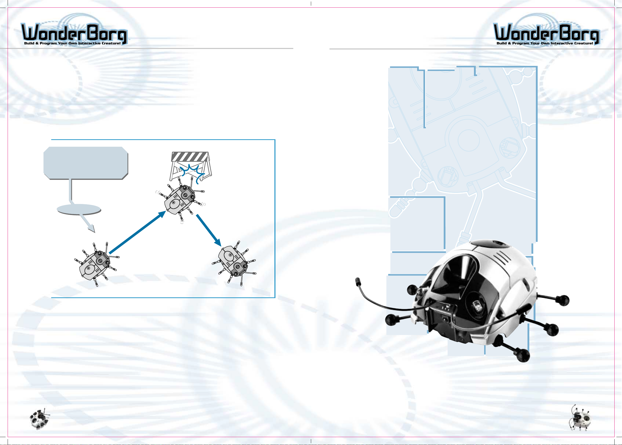
For example, you could program the WonderBorg as follows: "if either antenna sensor
reacts, turn four steps to the right " and "if there is nothing there, move forward
(advanced)". In this case, the WonderBorg will change direction when it bumps into an
obstacle, as shown in the illustration below. If none of the Sensors are activated,
the WonderBorg will walk forward.
To make the WonderBorg Change direction when it bumps into an obstacle:
Example:
- If either antenna sensor
reacts, turn four steps to
the right.
- If there is nothing there,
move forward.
Antenna touched
object, so turn 4
steps to the right
Programming
Nothing there,
so advance
forward
Nothing there, so
advance forward
How to Make the WonderBorg Work
1. Assemble the WonderBorg
2. Connect the Interface
3. Install Robot Works on your PC
4. Use Robot Works to create a program
5. Transmit your program to the a WonderBorg
6. The WonderBorg will move.
AUTONOMOUS
5
- See the "HARDWARE" section, starting on page 7, for instructions on assembling the
WonderBorg.
This section also contains a parts list for the WonderBorg kit, and gives the name
and function for each part.
- See the "SOFTWARE" section, starting on page 24, for instructions on installing
Robot Works, connecting the Interface, transmitting programs to the WonderBorg, and
making the WonderBorg move.
INFRARED RECEIVER
PROGRAMMABLE
CUSTOMIZE
6
Page 5
HARDWARE BASICS
HARDWARE BASICS
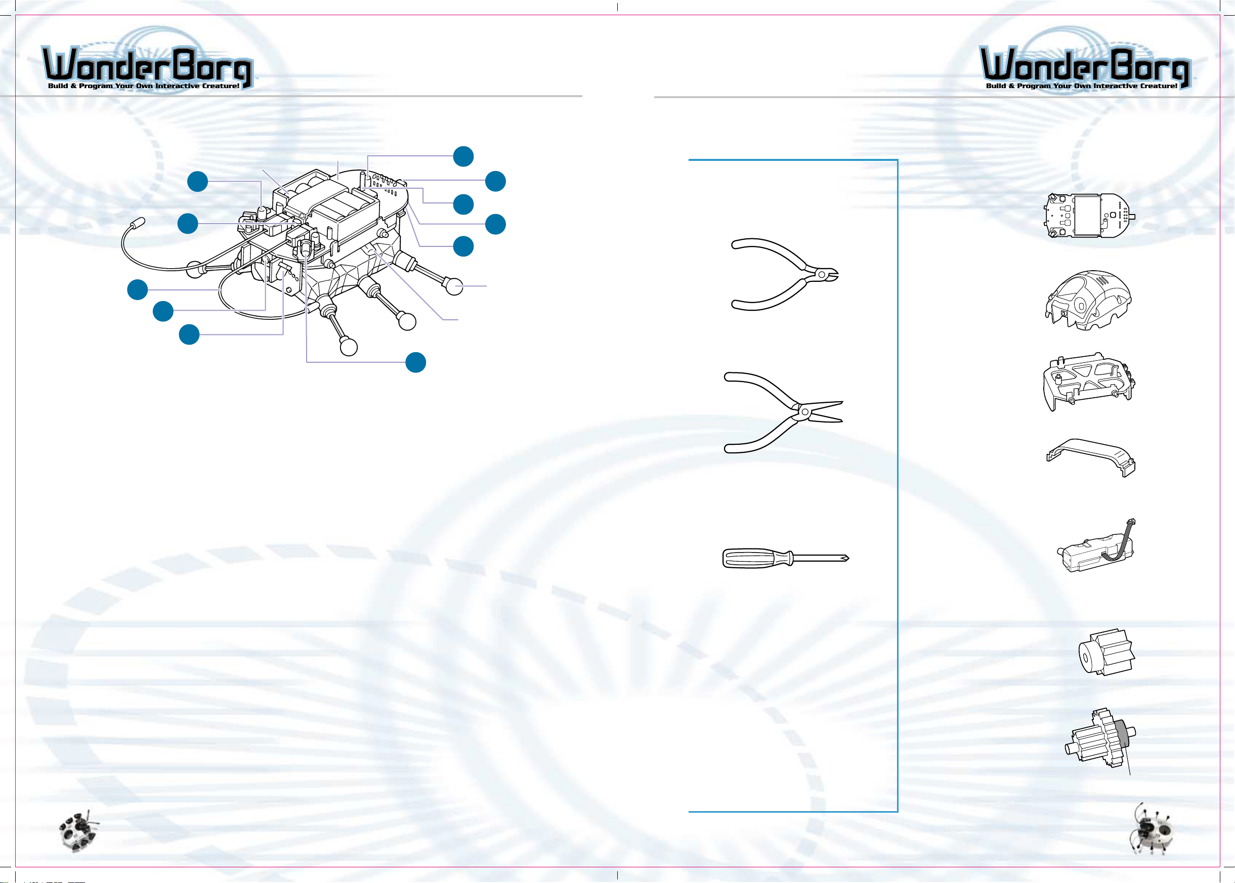
Names of Parts
Motherboard
Battery
3
8
9
7
6
5
1. POWER switch
When this switch is turned ON, the WonderBorg enters standby mode. When the
WonderBorg is not in use, this switch should be turned OFF.
2. START/STOP switch
If this switch is pressed once while the power is ON, the WonderBorg will start
moving in accordance with the program. If the switch is pressed again, the WonderBorg
will stop moving.
4
1
2
11
10
Leg
Motor Unit
Note: These tools are not supplied with
this product.
Wire-cutters
Needle-nose pliers
List of PartsTools Required
Electronic
Parts
Motherboard: 1
Plastic Parts
Body Shell: 1
Frame: 1
Battery Cover: 1
3. Eye (Red LED)
This LED is a Light-Emitting Diode. The eyes will flash when the WonderBorg detects
the presence of a wall, or an infrared signal. The flashing of the eyes is
controlled by Robot Works.
4. Green LED
This LED flashes while the program is being executed, and while the program is
being halted. When the floor sensor is OFF, the green LED flashes rapidly. When
the POWER switch is turned OFF, the green LED goes out.
5. Infrared LED 1
This LED sends out infrared rays. It is used to detect obstacles lying ahead and
to send signals to other WonderBorgs.
6. Infrared LED 2
This LED sends out infrared rays to keep track of whether the floor is there
or not.
7. Infrared Receiver
This is the sensor that receives infrared rays. It receives programs with infrared
signals.
8. Light Sensor
This is the sensor that detects whether the WonderBorg’s surroundings are light
or dark.
9. Antennae
The socket of each of the antennae is a sensor. The WonderBorg can be programmed
to react when one or both of its antennae touch something.
Philips screwdriver
Note: This tool is used in the Hardware
Variations section.
Others
AA alkaline battery: 2
AAA alkaline battery: 3
Note: The AA and AAA batteries are
not included with this product and
must be purchased separately
Motor Parts
Motor unit: 2
Replacement
Gears
Pinion Gear 2 (white)
(low-speed, high-torque
type) 2
Gear Unit A-2 (lowspeed, high-torque
type) 2
7
10. Connector
This connects the motors units and the motherboard.
11. Option Connector
This is an external input / output terminal. It can be used to add an extra sensor
or other device.
Black ring
8
Page 6
HARDWARE BASICS HARDWARE BASICS
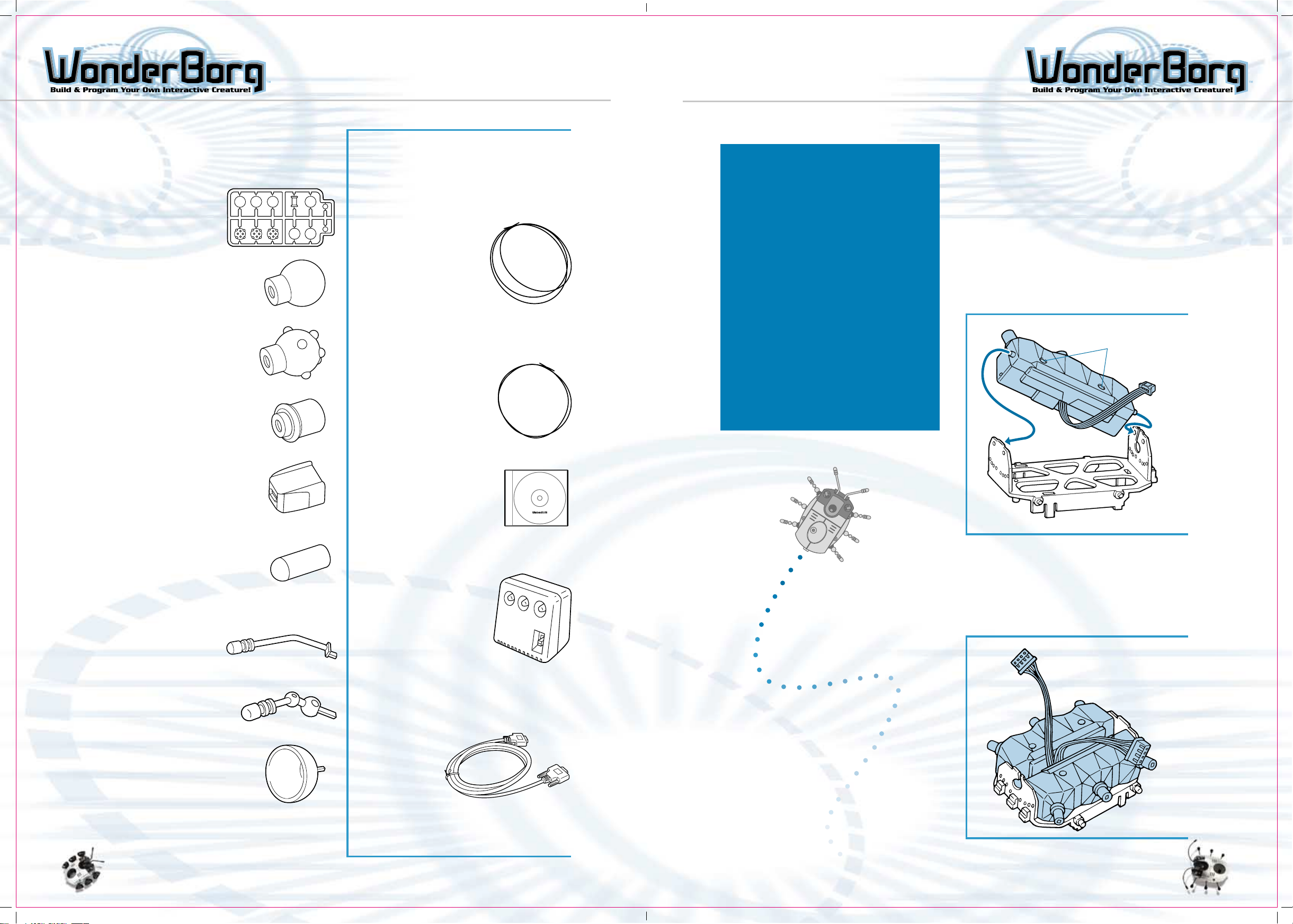
List of Parts
Set of Rubber Parts (with
runners)
Set of Rubber
parts: 2
Foot A: 6
Foot B: 6
Leg Housing: 2
Other Parts
Special plastic leg wire (thick): 1
Special plastic antenna wire (thin): 1
Now, at last, you are ready
to start assembling the
WonderBorg.
Please be sure to follow the
instructions exactly.
You will need to be extremely
careful, because you are going
to assemble a set of precision
electronic parts.
Be careful not to mix any of
the parts which look similar
to one another, such as the
gears.
But don’t worry too much, or
it won’t be any fun. Have fun
assembling your WonderBorg just take it nice and slow.
The Basics
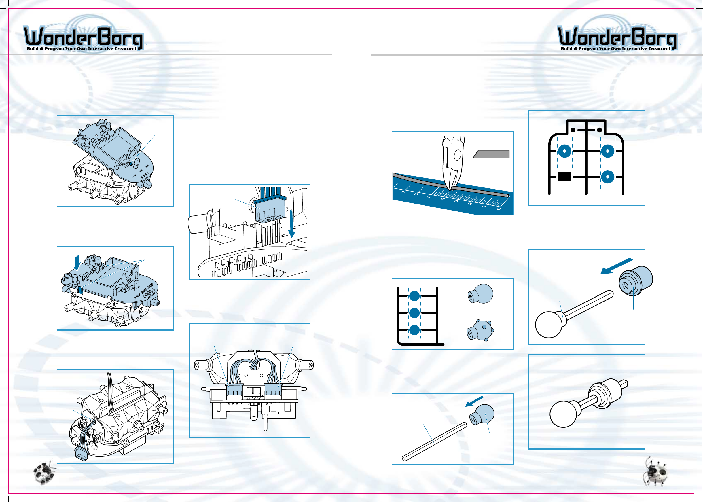
Assembling the Mechanism
1-1
Using your fingers to open the frame
slightly, take one of the motor units and
slot the pins on its front and rear into
the holes in the frame. The motor unit
should be inserted so that the cable exit
is facing the inside, and the screws are
uppermost.
Note: Be careful to insert the motor unit
the right way up.
Screws
Antenna socket: 2
Antenna Protector: 4
(2 are spares)
Plastic Antenna: 4
Plastic Leg: 8
Tire Foot: 8
Robot Works CD: 1
Interface: 1
Interface Cable
(RS-232C serial connection): 1
1-2
Insert the other motor unit in the same
way. Make sure the cables are protruding,
as shown in the diagram. The assembly
of the WonderBorg mechanism is now
complete.
9
Sheet of decals: 1
Instruction Manual (this manual): 1
Test Field: 1
10
Page 7
HARDWARE BASICS HARDWARE BASICS
Installing the Motherboard
2-1
Slot the hook on the frame into the hole
at the rear of the motherboard.
Hook
MotherboardMotherboard
RearFront
2-2
Press the motherboard down with your
fingers until the pawls click into place,
preventing the motherboard from being
pulled off.
Push down into Place
Pawls
2-4
Plug the motor unit connectors onto the
connectors on the rear underside of
motherboard. The connector from the motor
unit installed on the left should be
plugged into the motherboard’s left
connector, and the connector from the
right motor unit should be plugged into
the motherboard’s right connector. (Do
not plug either into the motherboard’s
central connector.)
Note: Make sure the connectors are facing
the same way, as in the diagram. The four
pins of each motherboard connector should
be inserted into the holes.
Connector from
left motor unit
Fitting the Legs
3-1
Using a pair of wire-cutters, cut the plasticcovered leg wire into lengths of about 4cm.
Cut the segments at a slight angle, so that
they will be easier to insert later. Cut
six identical segments. Use the handly
ruler on page 56 of this manual.
Cut at a
slight angle
3-2
Using the wire-cutters, snip either "Foot
A" or "Foot B" off the runners. When you
do this, snip close to the foot. Snip out
all six units.
Note: Foot A - These work best on flat, even
surfaces.
Note: Foot B - These provide a good grip
on uneven surfaces.
3-4
Using the wire-cutters, Snip out the six
leg housings from the runner.
3-5
Insert one of the legs into a snippedout leg housing. Do this for all six
legs.
2-3
Pass the motor unit cables through the
hole in the rear of the frame. Guide them
through the hole one at a time.
Front
Hole
Rear
2-5
When both motor unit connectors are
plugged into the motherboard, the
installation of the motherboard is complete.
Connector from Left
Motor Unit
Connector from
Right Motor Unit
Leg
Foot A
Leg Housing
Foot B
3-3
Insert one end of a segment of plasticcovered leg wire into one of the Foot A or
Foot B units, pushing it in as far as it
will go. Do the same for all six units.
Segment of a
plastic-covered
leg wire
Foot A (or B)
1211
Page 8
HARDWARE BASICS
HARDWARE BASICS
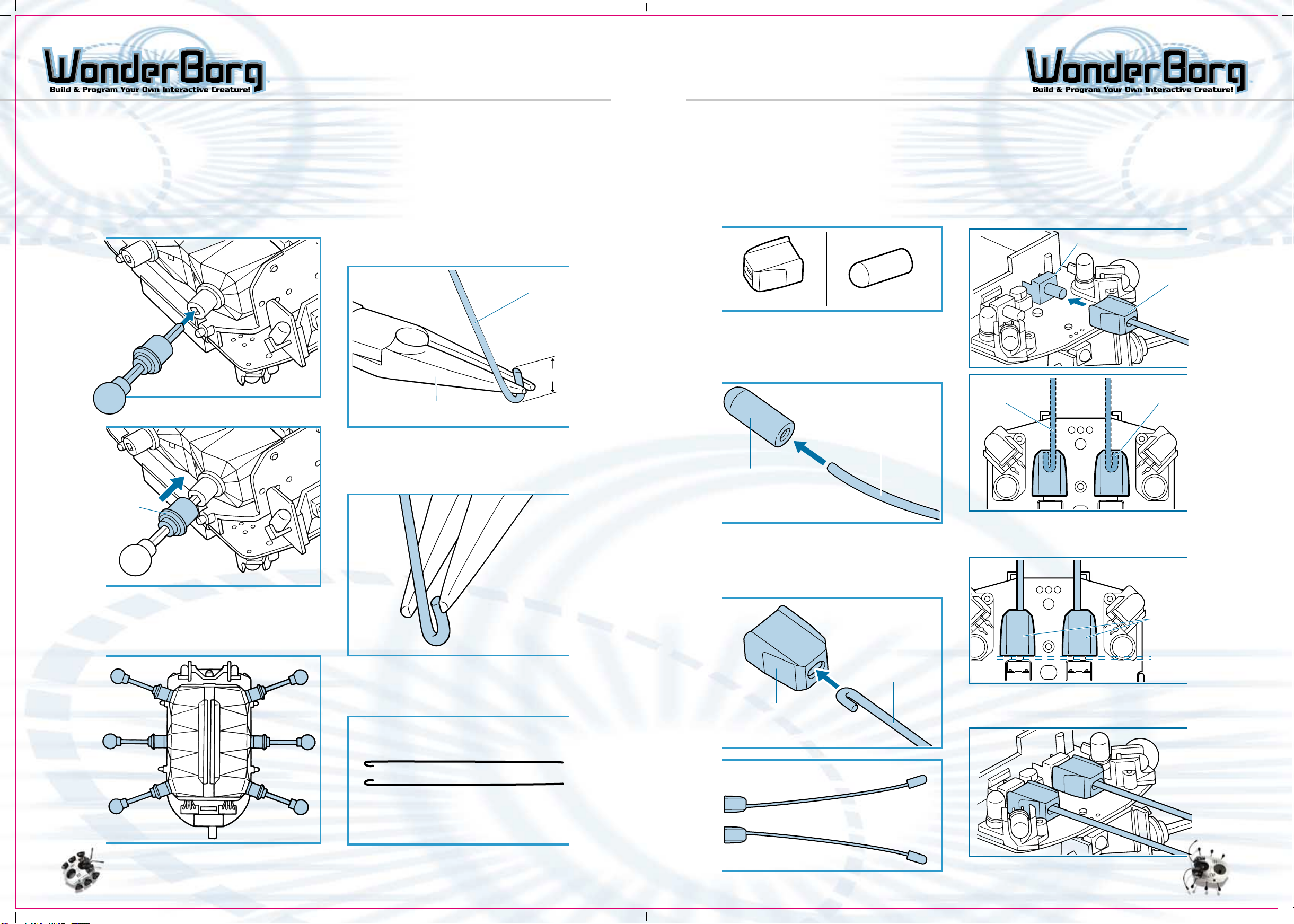
Fitting the Legs
3-6
Insert the legs into the sockets on the
WonderBorg’s body.
Push each segment of plastic-covered leg
wire into the socket as far as it will
go. If you have difficulty inserting the
wire, push it in from a slight angle.
Fitting the Antennae
4-1
Using the wire-cutters, cut a length of
about 15cm off the plastic-covered antenna
wire (use the handy ruler on the page 56
of this manual).
4-2
Using the needle-nosed pliers, bend back
the last 5mm or so of the wire.
Antenna Wire
5mm
Needle-nosed pliers
Fitting the Antennae
4-5
Using the wire-cutters, snip two of the
antenna sockets and two of the antenna
protectors off the runner. (The other
two antenna protectors are spares.)
Antenna ProtectorAntenna Socket
4-6
Insert the end of one of the segments of
plastic-covered antenna wire into an
antenna protector as far as it will go.
Do the same with the other one.
Plastic-covered
Antenna Wire
4-8
Plug one of the antenna sockets on to one
the motherboard’s touch sensors, as shown
in the diagram. When you do this, the cut
end of the plastic-covered antenna wire
should be facing outwards.
Touch Sensor
Antenna
Socket
Long end on
the inside
Short end on
the outside
Leg
Housing
3-7
Fit all six legs in the same way. Fitting
the legs is now complete.
4-3
Using the needle-nosed pliers, squeeze the
bent end of the wire to sharpen the bend.
4-4
Do the same thing to another identical
piece of wire.
Antenna
Protector
4-7
Insert the bent end of one of the antennae
into one of the antenna sockets, as far
as it will go. Do the same with the other
one.
Plastic-covered
Antenna Wire
Antenna
Socket
If you push the antenna socket too far
in, the touch Sensor may be unable to
react. Leave a space of about 1 mm.
View from above
Antenna
Socket
When both the left and right antenna
sockets have been installed, the antenna
installation is complete.
The WonderBorg’s body is now complete.
1413
Page 9
HARDWARE BASICS HARDWARE BASICS
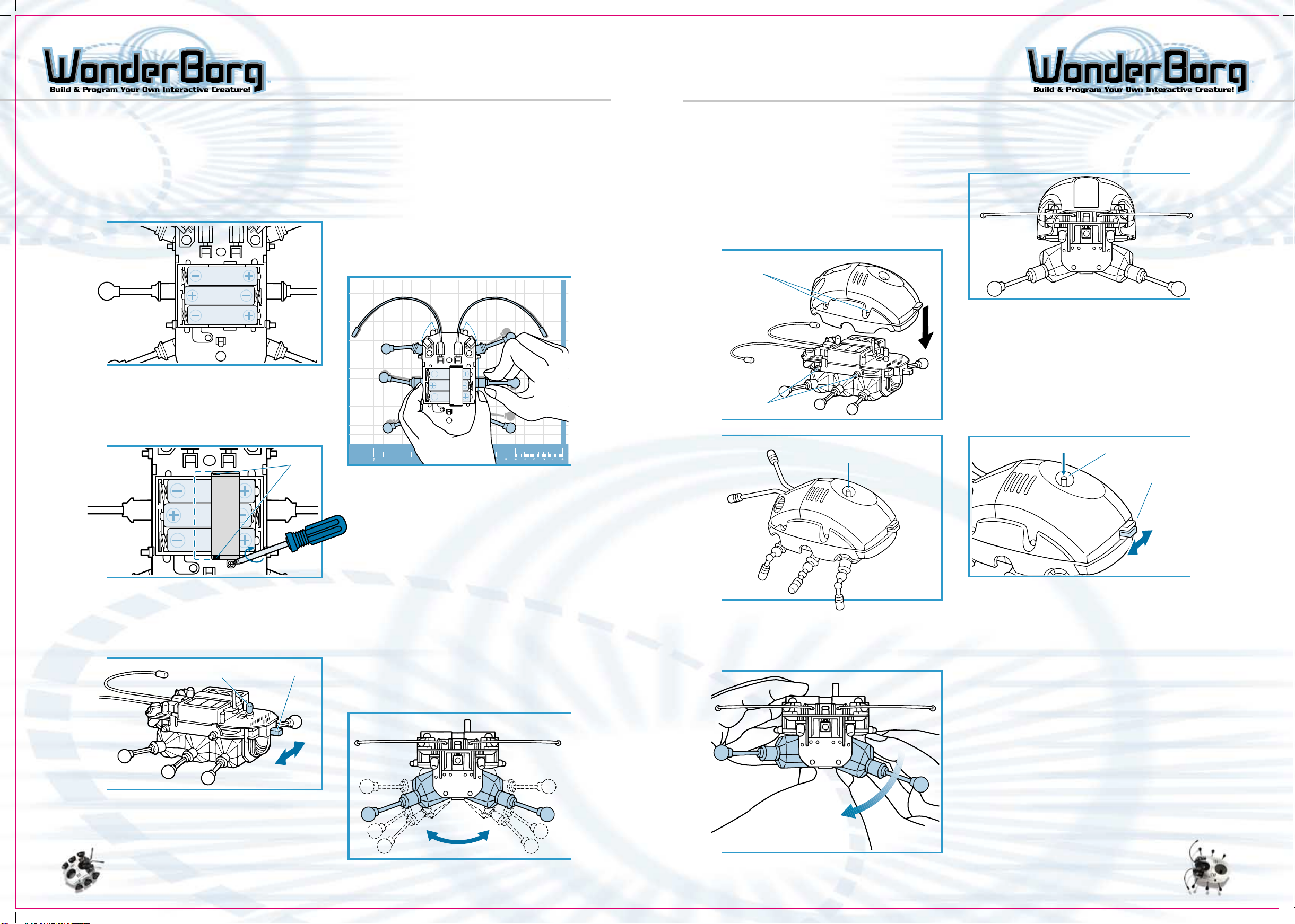
Bending the Legs and Antennae
5-1
Insert three AAA alkaline batteries (sold
separately) in the WonderBorg, as shown
in the diagram. Be careful to insert the
batteries the right way.
AAA/LR03 1.5V
AAA/LR03 1.5V
AAA/LR03 1.5V
5-2
Place the battery cover on top of the
battery box. Be careful to position the
battery cover with the holes positioned
as shown in the diagram.
5-4
Turn the POWER switch ON.
5-5
Place your WonderBorg on the leg and Antenna
Bending Template on the page 56 of this
manual. Bend the legs and antennae to match
the illustration. They can be adjusted to
any position. Once you have finished the
adjustments, turn the power OFF.
Fitting the Body Shell
6-1
Press the body shell down on to the
WonderBorg s body so that the pins on the
left and right side of the frame slot
into the holes in the body shell. The
START / STOP switch should protrude through
the hole.
Align the holes with the Pins
Holes
Pins
The START / STOP Switch should
Stick out through the hole
Push Down
Operational Testing
The WonderBorg is now complete. Next, carry
out the following operational tests.
7-1
Place the WonderBorg on the floor and turn
the POWER switch ON. The legs should move
slightly, then stop immediately. The
WonderBorg should emit a beeping noise,
and the green LED should light up.
7-2
Press
START / STOP
Switch
AAA/LR03 1.5V
AAA/LR03 1.5V
AAA/LR03 1.5V
5-3
Turn the WonderBorg’s POWER switch ON.
The WonderBorg’s legs will move slightly,
then stop immediately. The WonderBorg
will make a beeping noise, and the green
LED will light up.
Green LED Power Switch
[ON]
[OFF]
If the WonderBorg does not work, check
whether you have made a mistake in the
assembly operation.
Points to check:
- Are the connectors plugged in correctly?
- Are the batteries inserted the
right way?
The bending of the legs and antennae is
now complete.
Note: When the power is ON, the legs may
move, so turn the power ON before adjusting
them.
Extra Information
By changing the angle of the motor units,
you can adjust the height of the WonderBorg.
Note: If you adjust the angle of the motor
units closer to the vertical direction
(making the body higher), the WonderBorg
will walk more smoothly over obstacles,
but it will also be more prone to falling
over.
Likewise, if you adjust the angle of the
motor units closer to the horizontal
direction (making the body lower), the
WonderBorg will be less prone to falling
over, but it will also be less inclined
to walk over obstacles. The angle is altered
in four stages.
6-2
Adjust the angle of the left and right
motor units one stage away from the
horizontal, so that they are slanted like
the sides of the letter "A".
Adjust the angle of both
motor units by one Stage
Power Switch
[ON]
[Off]
7-3
The WonderBorg should emit a modulated
beeping noise and start walking.
7-4
The WonderBorg is pre-programmed with a
test program (which is erased when you send
it new data). Please check the following
functions.
- Press right antenna: Rotates to the right
- Press left antenna: Rotates to the left
- Obstacle to right: Right eye LED flashes
- Obstacle to left: Left eye LED flashes
If the WonderBorg does not work correctly,
check whether you have made a mistake in
the assembly operation.
Point to check:
- Are the connectors plugged in correctly?
- Are the batteries inserted the right way?
7-5
To halt the WonderBorg, press the START /
STOP switch again.
7-6
Turn the POWER switch OFF. The
operational testing is now over.
1615
Page 10
HARDWARE VARIATIONS HARDWARE VARIATIONS
Variation:
The operations described from this point on are variations. If you
are interested, try them for yourself: however, they are not essential.
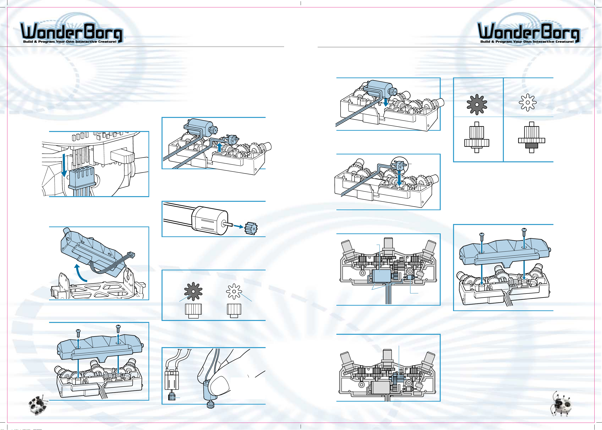
Changing the Gears
By changing the gears on the motor units, you can determine whether to prioritize
speed, or power.
8-1
Turn the POWER switch OFF, then unplug
the motor unit connectors from the
motherboard. When you do this, be careful
not to bend the pins of the motherboard
connectors.
8-2
Remove both motor boxes (including the
cables) from the frame. It is easier if
you remove the legs first.
8-4
Remove the motor switch form the gearbox
(below).
8-5
Using needle-nosed pliers or any other
suitable tool, remove the pinion gear from
the motor. As you do so, be careful not
to damage the teeth of the gear.
8-8
Install the motor in the gearbox (below).
8-9
Install the switch in the gearbox (below).
White peg
should be
uppermost
Pass the cables from the motor and the
switch through the gap as shown in the
diagram below.
If you are using pinion gear 1, use Gear
Unit A-1, and if you are using pinion
gear 2, use Gear Unit 1-2.
Pinion Gear 1
(initial High-speed
type setting)
Gear unit A-1 Gear unit A-2
Pinion Gear 2 Lowspeed, high torque
8-11
Secure the gearbox in position by fastening
the screws, and re-assemble the motor
unit. Fasten the screws firmly to eliminate
any gear between the upper and lower
parts of the gearbox. When you do this,
be careful that the cables pass correctly
through the gap, and are not caught
between the parts of the gearbox. Use
the same pinion gear, are gear unit A,
for both motor units.
8-3
Remove the screws and open the motor box.
8-6
Select a pinion gear.
High-speed type (black): High speed, low
power. Low-speed, high-torque type (white):
Low speed, high power.
Pinion gear 1 Highspeed type (initial
setting)
Profile
is Black
Pinion gear 2 Lowspeed, high-torque type
White
8-7
Press the selected pinion gear on to the
motor. Press firmly as far as it will go.
Take
care to
keep it
straight
Place pinion
gear on a flat
surface (desk),
and then press
the motor in.
Motor
Pass cables
through this gap
Switch
8-10
Change gear unit A (hold it so that you can
lift it from above).
Gear unit A
8-12
Attach the motor units to the frame and
attach the connectors to the motherboard
explained on page 11. When you have done
this, the replacement of the gears is
complete.
1817
Page 11

HARDWARE VARIATIONS HARDWARE VARIATIONS
Assembly Variations
9-1
Fitting Plastic Leg and Antenna Parts
Antenna
Socket
Antenna
Leg
Fit the legs on the other
side in the same way.
Use these parts if you prefer to make the
assembly process as easy as possible.
Note: Turn the power ON before adjusting the angle of
the legs.
9-2
Fitting the Tires
Leg Housing
Left
Right
Fit each of the legs at
the angle shown in the
diagram
The Option connector
The WonderBorg has an Option connector,
allowing even more advanced remodeling.
The Option connector is on the underside
of the WonderBorgs rear end, and allows
you to connect one external load such
as a motor, or one external sensor such
as a switch. To use this connector, you
will need general knowledge of electrical
circuits, a 2.54mm pitch, 4-pin connector
(female) Morex type or other connector,
and the ability to perform soldering.
Care is needed when using the Option
Connector: creating an inappropriate
connection may damage the WonderBorgs
circuits.
Caution
Option Connector 2.54mm pitch, 4-pins
may have sharp points.
Specifications
OUTPUT Supply voltage: 4.5V, maximum supply current: 500mA, ON / OFF only
Out +: Current output connected to robot’s battery +
Out -: Open corrector
INPUT Mechanical electrical contact points (switches, etc) short-circuit resistance:
1kΩ or lower
Switch input A: Microcomputer input, pulled high (100kΩ)
Switch input B: Connects to GND (robot’s battery -)
This connector allows an additional motor to be added.
Pin Layout and Reference Circuit
Caution
If an inappropriate external circuit is connected to the Option Connector, this
may result in damage to either or both the WonderBorg and the external circuit.
Only connect an external circuit if you are fully aware of its specifications.
Underside of WonderBorgs rear end
Option Connector 2.54mm
pitch, 4-pins
Tire
Fit the tires on the other
side in the same way.
Leg Housing
Option Connector
Rear End of
WonderBorg
Use a 2.54mm pitch, 4-pin connector such as a Morex.
Output +
Output -
o.1uF
Ceramic condenser
Note: A ceramic condenser must
be connected, or else the
WonderBorg may malfunction.
Switch input A
Switch input B
- Unpressed: reacts to sensor when Option is in State 0
- Pressed: reacts to sensor when Option is in state 1
Load such as motor
select a load between 3 and 4.5
V, and not more than 500mA
(This device can be switched ON
for a given period of time using
the
"Option ON" command.)
Microswitch
2019
Page 12
HARDWARE VARIATIONS ROBOT WORKS: CONTENTS
Personalize your WonderBorg
Software License Agreement ------------------------------ 52
Introduction -------------------------------------------- 23
Use the stickers / decals
(included) to decorate the shell
of your WonderBorg. Paint can
also be used to customize the
shell (paint sold seperately).
Setup: Preparing to Use Robot Works
Installing the Software ------------------------------- 24
Connecting the Interface ------------------------------ 25
The Names of the Interface Parts, and What They Do ---- 26
Setting the Serial Port ------------------------------- 27
Overview of the Programming Operation:
Robot Works Explained
Over View of the Programming Operation ---------------- 28
Let,s Get Started! ------------------------------------- 29
How to Read the Screens ------------------------------- 31
Names of Parts ---------------------------------------- 33
Programming:
How a Program is Created
How to Read the Blocks, Operations Carried Out on the
Panel Screen, How to Edit Blocks, How to Eliminate Unwanted
Blocks, Switching Panels ------------------------------ 36
The Sensor Block Factory
Names of Parts ---------------------------------------- 37
How to Create a Sensor Block, Frequently Used Sensors 38
List of Sensors --------------------------------------- 39
The Command Block Factory
Names of Parts, How to Create a Command Block --------- 40
Frequently Used Commands, List of commands------------- 41
Priority Order and Interrupts
Priority Order, Interrupts ---------------------------- 42
Transmitting program to the WonderBorg ---------------- 43
Saving a Program -------------------------------------- 43
Exiting from Robot Works ------------------------------ 43
The Set Up Screen:
The Settings Screen Explained
Names of Parts ---------------------------------------- 44
Programming:
Getting started: Programming Exercises
Exercise 1 ------------------------------------------- 47
Exercise 2 ------------------------------------------- 48
Exercise 3 ------------------------------------------- 49
Exercise 4 ------------------------------------------- 51
Pre-programmed Personalities -------------------------- 51
Trouble Shooting -------------------------------------- 53
2221
Page 13
INTRODUCTION SET UP
Introduction
Have you assembled your WonderBorg?
The WonderBorg is not operated by remote control: it is an autonomous robot. In
other words, it uses its own sensors to find out about its surroundings, and decides
for itself how it should move. If you teach your WonderBorg what to do in a given
situation, it will exhibit all sorts of behavior. This teaching process is called
"programming the WonderBorg".
Ordinary programming requires specialist knowledge of computers, but this is not
necessary to program the WonderBorg for PC. This is because you use special software
called Robot Works, which allows you to create programs very easily using your
computer,s mouse. Read on, and learn how to program your own WonderBorg by following
our practical guide.
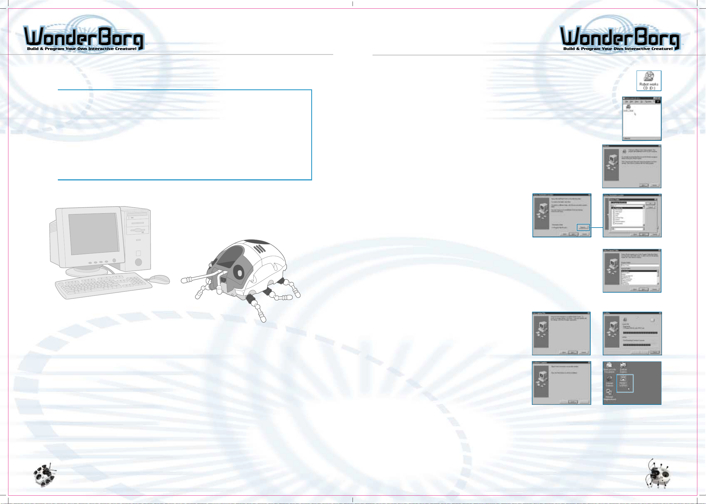
Installing the software
- To install Robot Works, you will need at least 30MB of
free disk space.
- Load the Robot Works CD in your PC>s CD-ROM drive.
- Go into "Robot Works CD" in "My Computer", and double-click the
"works-setup" icon. This will activate the Installation Wizard.
- When the Installation Wizard starts up,
click "Next". If you have any other programs
open, close them and then restart the
Installation Wizard.
Robot Works software is designed exclusively for Windows ME / 98 /
95. Robot Works uses your PC’s external serial port, so have your
PC manual in hand when you begin the setup operation.
System Requirements
- A DOS / V format PC.
- A PC running Windows ME / 98 / 95, and having a D-sub 90-pin serial connector.
(If your PC has a different type of serial connector, you will need suitable adapter.
Contact your PC,s manufacturer for more information. The use of a USB-to-Serial
adapter is not recommended.)
- The PC must be a Pentium 100MHz or higher, with at least 32MB of memory, 16-bit
color capability or higher, and least 30MB of free disk space.
- A CD-ROM drive is also required, but only when installing the software.
- Specify where you want the software to be installed. Most people
choose the default option and click "Next" (in this case, the software
will be installed in the Program Files folder in the C drive.).
If you want to install the software to another location, click
"Browse". The directory selection screen will then appear. Specify
the desired directory, then click "OK".
- It is now time to specify whether you want Robot Works to appear
in the Start menu of in a particular program folder. Most people
choose the default option and click "Next" (in this case, the
software will be installed in the Robot "Works" folder.).
- If you want to change the name of the folder,
enter the desired name in the topmost box,
then click "Next".
- The screen asking you to confirm whether
to go ahead with the installation will now
appear. Most people choose the default option
and click "Next". In this case, the installation
will begin. If you want to change any detail
of the installation, click on "Back" and
re-set the item in question.
- The Robot Works installation status screen
will now appear. When the progress meter
reaches 100%, the installation is complete.
When the screen tells you that the installation
has been carried out successfully, click
"finish". Robot Works is now installed.
- If you chose the relevant default option earlier, the Robot Works shortcut icon will
now be present on the Desktop screen. To activate Robot Works, double-click this icon.
Note: If the Robot Works icon is not on the desktop screen, go into the Windows star menu,
select "Programs", then select "Robot Works", then "Robot Works" again, to activate the
program.
Uninstalling Robot Works
To uninstall Robot Works, go into "My Computer", select "Control Panel", select "Add /
Remove Programs". When "Add / Remove Programs Properties" is displayed, Select :
"Robot Works" from the list of applications, and click "Remove". Follow the on-screen
instructions to remove the application.
2423
Page 14

SET UP SET UP
- Connecting the Interface
Caution: Be sure to switch the PC power OFF
before starting this operation. Use only
the Interface supplied with this product.
Make sure that no other device is connected
to the external serial port of your PC.
1 Connect the Interface to the PC’s serial
port (COM port) using the Interface Cable
supplied with this product. Refer to your
PC manual to avoid making a mistake.
If your PC has more than one serial port,
connect the Interface to COM1.
Note: If you own a palm pilot or similar device, you must temporarily disable it in
order to attach the interface. These devices take control of the output port and will
not allow the interface to connect. Simply click the mouse on your Hot Sync Manager
icon (located on the bottom right corner of the screen), and click disable. Do the
same to enable it when you are finished playing with the WorderBorg.
PC’s serial port
(COM port)
Caution
If you are using a notebook PC, for example, the serial port may be the wrong shape
for the connector, and in this case you will need a serial port (COM port) adapter.
Consult your PC manufacturer for more information. The use of a USB-to-Serial adapter
is not recommended.
2 Remove the battery cover from the Interface supplied, and insert two AA alkaline
batteries as shown in the diagram. Be careful not to insert the batteries the wrong
way. Replace the battery cover, then turn the POWER switch ON. If the green lamp
(labeled "POWER") on the front of the Interface lights up, it is connected correctly.
Inserting the Batteries
View
from Rear
Battery
Cover
3. Connect the supplied cable to the connector
in the back of the Interface.
Note: Do not fasten the screws on the left and right
sides of the connector.
Note: Do not touch the terminal with your fingers
Top
Make sure the cable’s own
connector is the right way up.
To Ensure Proper Function
- Do not mix old and new batteries.
- Do not mix alkaline, standard (carbon-zinc), or rechargeable (nickel-
cadmium) batteries.
- Battery installation should be done by an adult.
- Non-rechargeable batteries are not to be recharged.
- Rechargeable batteries are to be removed from the toy before being charged
(if removable).
- Rechargeable batteries are only to be charged under adult supervision
(if removable).
- Only batteries of the same or equivalent type as recommended are to
be used.
- Batteries are to be inserted with the correct polarity, and follow the
toy and battery manufacturer’s instructions.
- Exhausted batteries are to be removed from the toy.
- The supply terminals are not to be short - circuited.
- Do not dispose of batteries in fire as batteries may explode or leak.
Bottom
Battery
First, insert the bottom of the battery
cover into the cavity, then slide the
battery cover up
Battery Cover
Connector
Screws
Names of Interface Parts and Their Function
Infrared Transmitter
- Sends programs and Infrared
signals to the WonderBorg.
Battery Cover
Power Lamp
Glows green when
Power switch is ON
Indicator Lamp
Flashes when a program
or infrared signal is
being transmitted
Power Switch
The "up" position is ON
and the "down" position
is OFF. Be sure to turn
this switch off when the
equipment is not in use.
Cable Connector
- Connects to the
WonderBorg’s special
Interface Cable. Do not
insert any other cable as
this could cause the interface
to break down.
Points to note
- The Interface is a piece of precision electronic equipment. Be careful not to drop
it, allow it to get wet, or leave it inside a car during hot weather or anywhere
else likely to become very hot, as this could cause it to break down.
- The only cable that should be inserted into the connector on the Interface is the
special Interface Cable.
Do not insert any other cable, or any small metal objects such as paperclips
or pins.
- Do not touch the Interface Connector terminal with your fingers, or allow any metal
objects to come in contact with it.
- The battery life is roughly 100 hours (using a commercially-available alkaline
battery).
- If communications errors are becoming more frequent during program transmission
(when a communications error occurs, the WonderBorg will emit a long beep), change
the batteries. When you do so, replace both batteries with new ones, and make sure
the batteries are inserted the correct way.
Using the Interface as an Infrared Signal Transmitter
The Interface can be used to transmit infrared signals to the WonderBorg to guide it
and perform other operations. To transmit an infrared signal, bring up the Settings
screen in Robot Works, select the type of infrared signal you want to send, then click
the START button on the screen.
The flashing of the indicator lamp when an infrared
signal is transmitted
When an infrared signal is transmitted, the indicator lamp on the Interface flashes
(see chart below).
Pattern
is
Indicator
Flashes
Flashing Stars for
approx. 1 sec.
Indicator
Flashes
Flashing Stars for
approx. 1 sec.
Repeated
2625
Page 15

SET UP
OVERVIEW OF THE PROGRAMMING OPERATION
Setting the serial Port
Before using Robots Works for the first time,
you will need to set the serial port. This is
done by opening Robots Works and following the
procedure described below.
1. When you open Robot Works, the title screen
will appear. If you left-click the "CLICK TO
START" button, the panel screen will then
appear.
2. Click the "Set Up" button on the panel screen
to bring up the settings screen.
Overview of the Programming Operation
The main operating screens in Robot Works, and the way they relate to one another, are
shown below.
Sensor Black Factory
1. Open Robot Works
Panel Screen
2-1 This Screen is used to
set variable Decimeters for
the sensors used in the program.
3. Using the "Com Port" button on the
Set Up screen, select the port to which the
Interface is connected.
4. Turn the Interface’s POWER switch ON, click
"Borg Signal" on the "START" button. If all
is in order, the red indicator lamp at the
left on the Interface will start flashing.
5. Click "STOP". The indicator lamp will stop flashing.
Click "Return" to return to the panel screen, then
click "Quit" to exit from Robot Works.
These settings only need to be specified the first time you use Robots Works. Your
settings will be saved, so there is no need to repeat the above procedure on subsequent
occasions.
Command Black Factory
2. Panel used to create Program
for WonderBorg.
Set Up Screen
This Screen is used to
specify the desired behavior
- pattern and the extent.
This screen is used to set
the sensor sensitivity, the
WonderBorg’s walking speed,
and the LED parameters.
3. The Infrared signal
is transmitted from
the interface to the
WonderBorg.
2827
Page 16

OVERVIEW OF THE PROGRAMMING OPERATION OVERVIEW OF THE PROGRAMMING OPERATION
Let's get started!
It’s time to try programming your WonderBorg.
1. Open robots works, and click "CLICK TO START" on the
title screen. The Panel Screen will then appear.
2. Left-click the blue square in the top left corner of
the screen. The Sensor block Factory screen will
then appear.
3. This screen is used to specify the sensor settings.
On the list, select "Nothing Here", then click the
"OK" button.
7. You have now created a program that says "When there is nothing there, the WonderBorg
must move forward".
8. Turn the WonderBorg’s POWER switch ON.
9. Position the Interface so that the
transmitter is facing the WonderBorg’s
infrared receiver (the WonderBorg should
be about 20cm away from the Interface).
When you do this, make sure there is
nothing in between the Interface and the
WonderBorg (see the illustration below).
Has to position the WonderBorg’s
relative to the interface
Power Switch
4. Go back to the Panel Screen. The "Nothing Here" block
will be displayed on the panel. Drag this block and
drop it on top of the blue square that you clicked
earlier.
5. The next step is to specify
a command. Left-click the
pink triangle beside the
"Nothing Here" Block. The
Command Block Factory screen
will now appear. On the
list, select "Advance",
then left-click the
"OK" button.
6. Go back to the Panel Screen. The "Advance" block
will be displayed. Drag-and-drop this block to the
right side of the "Nothing Here" block, using the
same procedure as in step 4.
10. Left-click "Dowload to Robot" at the top
of the Panel screen. Your program will
now be transmitted. The WonderBorg’s eyes
will flash, and when it emits a short
beep, the transmission is complete.
11. Press the WonderBorg’s START / STOP switch
once (causing the green LED to flash).
If the WonderBorg now moves continuously
forward, your program has been successfully
transmitted. Press the START / STOP button
again (the green Led will now go out) to
bring the WonderBorg to a halt.
Make sure there is
nothing in the way
Press
Start Switch
3029
Page 17

OVERVIEW OF THE PROGRAMMING OPERATION OVERVIEW OF THE PROGRAMMING OPERATION
How to Read the Screens
Operations are carried out using three basic screens: the Panel screen, the Sensor
Block Factory screen, and the Command Block Factory screen. This section explains the
role of each screen and how to switch between them.
When you open Robot Works, the title screen appears. Left clicking here will take you
to the Panel screen.
Go to Sensor Block Factory
Note: To go to the Sensor
Block Factory. Click one of
the blue squares on the Panel
Screen; to go to the command
black Factory, click one of
the pink triangles.
Go to Command Block Factory
The new block will appear here.
Drag it over and drop it at the
appropriate position on the panel.
The Sensor Block Factory
This screen is used to create new sensor blocks on the Panel screen. A sensor
block is a block specifying which sensor to use. It consists of yellow text
on a blue block.
The Panel Screen
This is the main screen used for programming the WonderBorg. Using the mouse to drag
and drop blue sensor blocks and red and green command blocks, you can create a program
very easily. (The illustration above shows a panel after a program has been input.)
The Command Block Factory
This screen is used to create new command blocks on the Panel screen. A
command block is a block specifying which command to execute. The command
consists of an icon and text on a red or green block.
3231
Page 18
THE PANEL SCREEN THE PANEL SCREEN
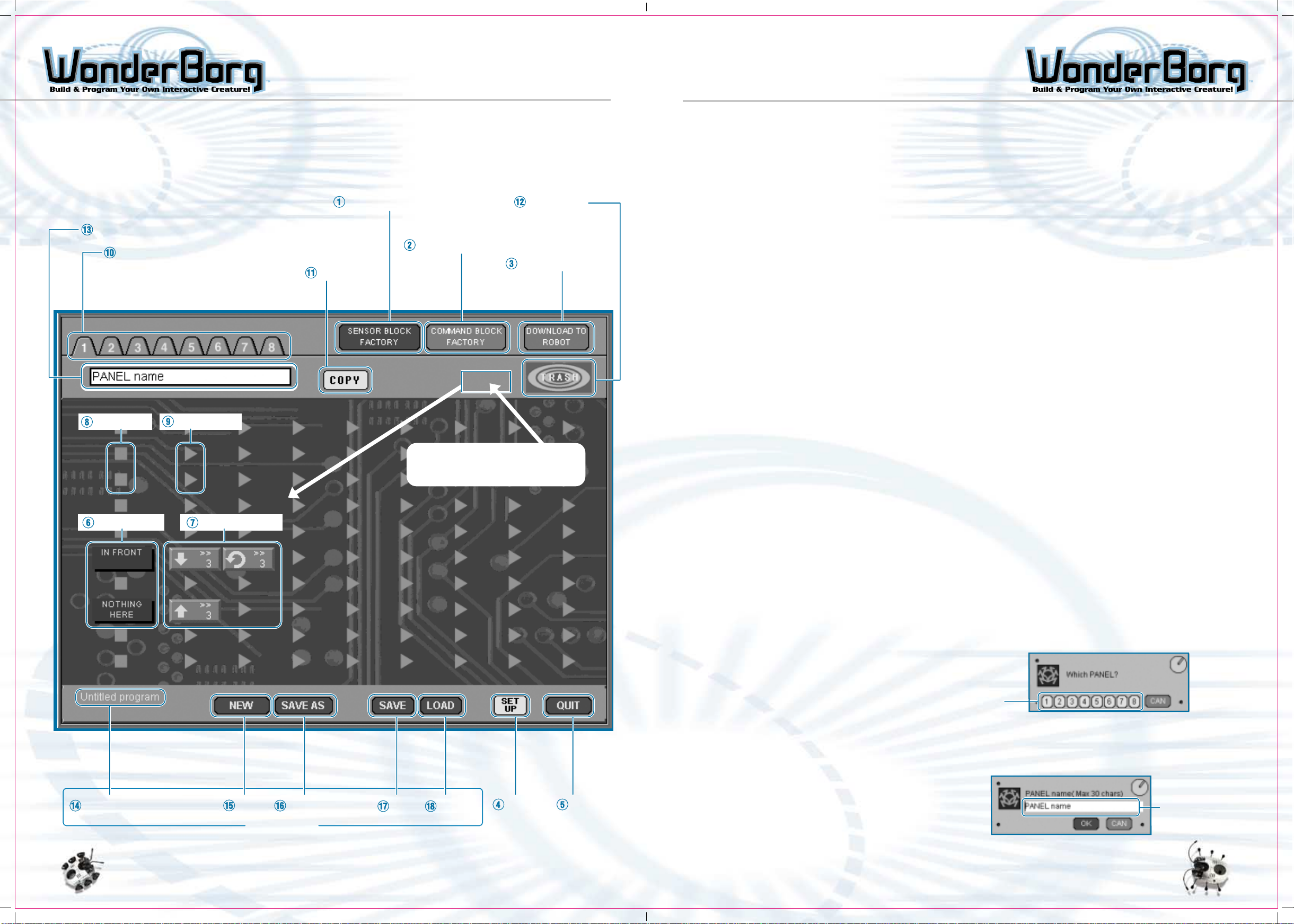
Names of Parts
This section gives the names of all parts of the Panel screen. The parts below are
defined on the following pages.
Sensor Block Factory
Panel Name
Switch Panels
Blue Square
Copy
Pink Triangle
Command Block Factory
The new block will appear here.
Drag it over and drop it on the
appropriate square / triangle.
Trash Can
Download To Robot
1. Sensor Block Factory:
Takes you to the Sensor Block Factory.
Note: You can also move to the Sensor Block Factory by clicking one of the blue squares
on the screen.
2. Command Block Factory:
Takes you to the Command Block Factory.
Note: You can also move to the Command Block Factory by clicking one of the pink triangles
on the screen.
3. Download To Robot:
Transmits the program on the Panel screen to the robot, via the Interface.
4. Set Up:
Takes you to the Settings screen.
5. Quit:
Terminates Robot Works.
6. Sensor Block:
A sensor block tells the robot which sensor to react to. Sensor blocks can be created
in the Sensor Block Factory and then dragged-and-dropped on top of one of the blue
squares on the panel. If the sensor block is linked to a command block, this command
block will come along too when the sensor block is moved. Double-clicking a sensor
block will take you to the Sensor Block Factory, where you can edit the block.
7. Command Block:
A command block defines the command to be executed. When used in a program, a command
block is always linked to a sensor block. Command blocks can be created in the Command
Block Factory and then dragged-and-dropped on top of one the pink triangles on the
panel. Double-clicking a command block will take you to the Command Block Factory,
where you can edit the block.
8. Blue Square:
Clicking a blue square will take you to the Sensor Block Factory.
Sensor Block Command Block
Program Name
New
Save as
Save
Load
Set Up
Quit
9. Pink Triangle:
Clicking a pink triangle will take you to the Command Block Factory.
10. Switch Panels:
This button is used to switch between Panels 1 to 8.
11. Copy:
This button is used to copy a block from another panel, to the panel currently displayed.
Rather than starting from scratch every time, it is quicker to create a new program by
modifying panels you created previously. When you click the "copy" button, a dialog
box will appear, asking you to select the panel you to copy. Click the number of the
desired panel, and the program will then be copied to the new panel.
Note: If you copy a program on to a panel that
already contains a program, the content of the
panel will be overwritten.
Click
12. Trash Can:
You can erase unwanted blocks by dragging-and -dropping them in the Trash can.
13. Panel Name:
This is the box where you type in the name of your
new panel (it is a good idea to give the panel a
name indicating what it does).
The name you give the panel has no actual
effect on the function of the program. When you
click "Panel Name", a dialog box appears,
asking you to input the name. If you want to
use Japanese script for the name, consult
your PC manual for instructions.
Input
Name
here
3433
Page 19
THE PANEL SCREEN PROGRAMMINNG
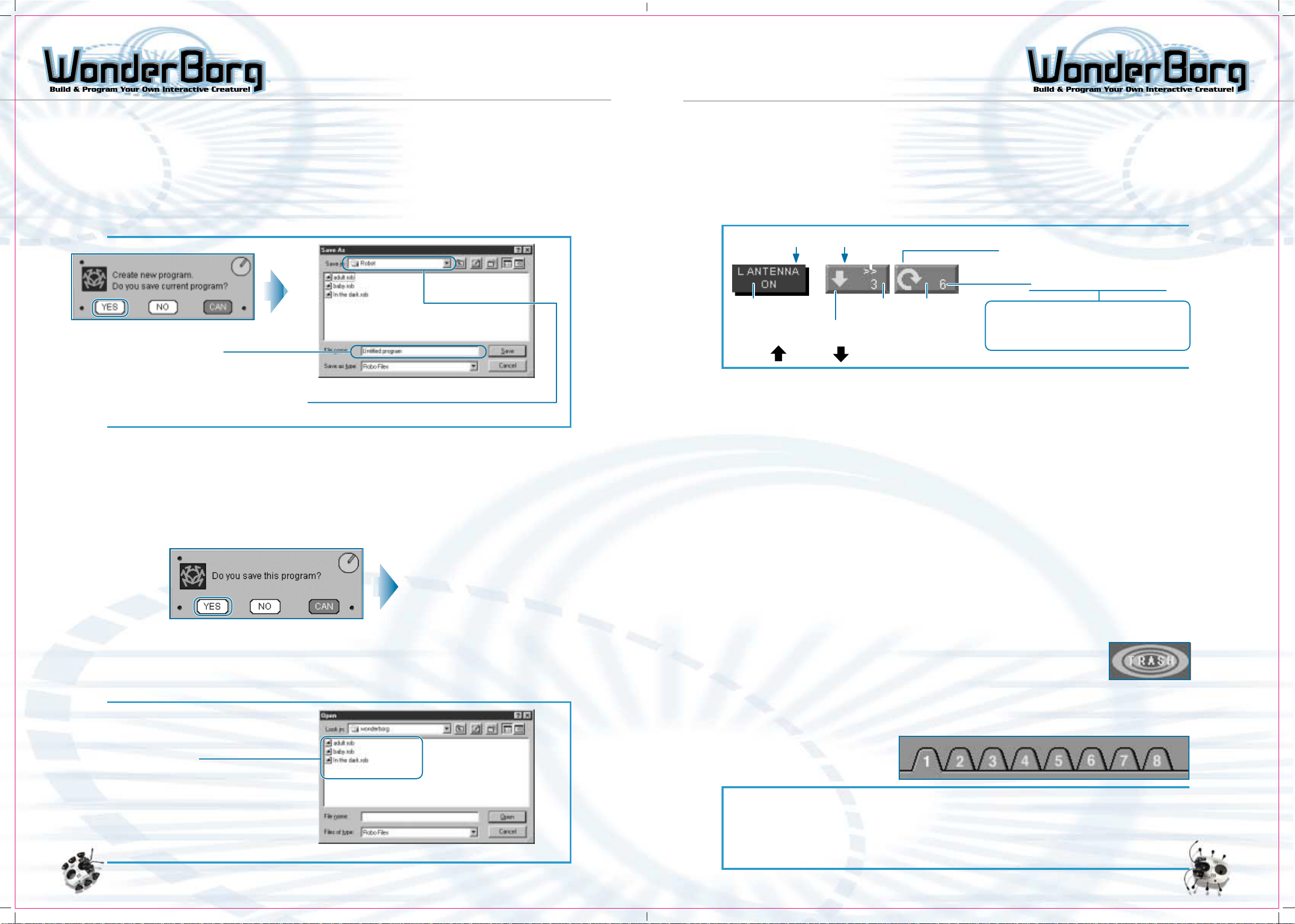
14. Program name:
This box displays the name of the file containing the current program. If you are
creating a new program, it will read "Untitled Program".
15. New:
If you click this button, the whole panel you are currently creating will be deleted,
and a new program will be created. If you click this button while in the middle of
creating a program, a save dialog window will open, allowing you to choose whether to
save the current program.
Input filename here
It is a good idea to save your program
to the "Robot" folder inside the "Robot
Works" folder.
Save Dialog
16. Save as:
This saves the program under another name. This useful when you want to edit an existing
program and save the revised version as a new program. When you click "Save as", a
save dialog window will open, allowing you to input the new name.
17. Save:
By clicking this button, you can overwrite the program you are currently creating. If
this is a new program, clicking "Save" will cause the save dialog window to appear,
allowing you to input the filename.
Programming
How to Read Blocks
This section explains how to read the sensor blocks and command blocks on the Panel
screen. Command categories are indicated by icons. In this example, the blocks are
"if the left antenna touches something", "go three steps back at high speed", and "rotate
six steps to the right at low speed".
Sensor categorize
A sensor block is
a blue square
Arrows indicate direction of movement
Forward Back
Operations Carried Out on the Panel Screen
1. A sensor block can be placed on top of a blue square on the panel. A command block
can be placed on top of a pink triangle in the same way. Blocks are moved by draggingand-dropping using the mouse.
2. Up to 10 sensors can be used per panel. Up to 8 command blocks can be linked to a
sensor block.
3. If you line up the desired command blocks on the right of sensor block, the corresponding
commands will be executed - in order, starting with the leftmost block - when the
sensor reacts. This is called "linking commands to a sensor block". When the sensor
block is activated, its linked commands will also be activated in sequence.
4. In a program using several sensor blocks, if two or more sensors react simultaneously,
the sensor which is highest on the panel will take priority.
5. The "No reaction" sensor block is a special block. It should always be used as the
last line in any program.
6. A single panel may contain up to 121 blocks, counting sensor blocks as 1 and command
blocks as 2.
Command icon
Command block is red or
green square (with
rounded edges).
Speed of movement stands for "High
Speed", blank stands for "Low Speed".
Number stands for of steps,
seconds, turns, etc.
Movement command: number of steps
Stop command: number of seconds, to stay
Voice command: number of cries
To save dialog window
18. Load:
By clicking this button, you can open a program you have previously saved. All program
files will end with the extension "rob". If you are in the middle of creating another
program, a window will appear, asking you whether you want to save this program.
Select the file you
want to open
Open Dialog
How to Edit Blocks
Double-clicking a sensor block or a command block will automatically take you to the
corresponding Block Factory screen. Here, you can edit the block (by changing the command,
the sensor, the number of steps, and so on).
How to Eliminate Unwanted Blocks
Command blocks and sensor blocks that you want to get rid of can be
erased from the screen by dragging-and-dropping them on the Trash can
icon in the top right corner of the Panel screen.
Switching Panels
Robot Works has 8 panels which can be input into a program. By clicking one of the
panel numbers at the top left, you can view the corresponding panel. You can input a
different program in each panel. In the case of the illustration below, Panel 1 is the
panel displayed on the screen.
If you click any other number,
the corresponding panel will
appear on the screen.
Using Panels
Within a program file, you can use the "Switch panel" command to switch to any given
panel (use the number keys in the Command Block Factory to input the number of the
desired panel) and make the robot execute the behavior-patterns specified by that
panel. When the WonderBorg is activated, it always starts from Panel 1.
3635
Page 20

THE SENSOR BLOCK FACTORY THE SENSOR BLOCK FACTOR Y
2-1 The Sensor Block Factory
You can move to the Sensor Block Factory screen by clicking "Create sensor block"
at the top of the Panel screen, or by clicking one of the blue squares on the
Panel screen.
Name of Parts
The names of the aparts are shown below. The numbers correspond to the numbered
explanations.
Help Screen
Sensor List OK
Cancel
How to Create a Sensor Block
On the Sensor Block Factory screen, select and click the desired sensor from the sensor
list in the middle of the screen. If you then click the "Decide" Button at the top
right of the screen, the Sensor block will be created on the Panel Screen.
Frequently-Used Sensors
The state in which no sensors are reacting is called the
NOthing Here
Right antenna
Left antenna
Both antenna
"Nothing Here" state. In this state, the "Nothing Here"
block is triggered. Any command you want the robot to
carry out all the time should be assigned to this sensor.
Note: This sensor should always be used in the last line
of your program.
These sensors react when one or both of the antenna touch
something. There is a sensor block for when the left
antenna touches something, a sensor block for when the
right antenna touches something, another for when both
antennae touch something at the same time, and so on.
The antennae made of plastic-covered wire can be bent
into any shape, so you can bend them to the best shape
for whatever you want the robot to detect.
Help
Block
1. OK:
Sends the created sensor block to the Panel screen.
2. Cancel:
Returns you to the Panel screen without creating a sensor block.
3. Sensor List:
List of the sensors that can be set.
4. Block
Displays the sensor selected from the sensor list.
5. Help:
Displays a help animation indicating the function of the sensor currently selected. To
stop the animation, click the button again (the text on the button will change to "STOP").
6. Help screen:
Screen area where the help animation is displayed.
Infrared signal 1
(Guide to goal)
Infrared signal 2
(Guide to
another robot)
Some of the sensor blocks use the infrared sensors, such
as "Infrared signal 1 (Guide to goal)" and "infrared
signal 2 (Guide to another robot)". The robot can pick
up infrared signal within a range of about 90 degrees
centered directly ahead.
Area in which Robot can pick up infrared signals
(Maximum) area in which robot will react
to infrared signals. The robot will react
to any infrared signal-emitting device
in this area.
Note: The greater the distance between
the robot and the infrared signal-emitting
device, the narrower the angle of the
boundaries the area in which the robot
can detect the signal.
3837
Page 21

THE SENSOR BLOCK FACTORY
OBJECT
OBJECT
OBJECT
THE COMMAND BLOCK FACTORY
Sensor Table
This table sets the function of each sensor
Touch sensor
- Right sensor
- Left antenna
- Both antennae
Infrared sensors
- Something ahead
to the right
- Something ahead
to the left
- Something ahead
Floor Sensor
- Floor sensor ON
- Floor sensor OFF
Sensor reacts
when antenna
touches something
Infrared ray
reflects off
obstacle
The Infrared ray emitted
by WonderBorg bounces
off obstacle & is detected
on way back
Floor Sensor - senses status
of floor in front of robot
ON = Floor
OFF = Floor is
Infrared
ray from
wonderBorg
Sensors will not react if robot is too
close to an obstacle shown (Dark-colored,
small objects that do not reflect much
infrared rays will not be detected.
Present
dark or absent
The wire
antenna can
be bent into
any shape
Front
Left
Infrared ray emitted by
WonderBorg is reflected back
& detected by the sensor when
detected sensor is ON.
Note: On certain floor surfaces,
this sensor will not react.
When it is off, the Green LED
flashes faster.
Right
Sensor may not
react if robot
is too close
to obstacle.
Approx.
10 cm
The Command Block Factory
You can move to the Command Block Factory screen by clicking "Create command block" at
the top of the Panel screen, or by clicking one of the pink triangles on the Panel screen.
Names of Parts:
The names of the parts are shown below. The numbers correspond to the numbered explanations.
Help Screen Command List OK Cancel
Brightness
sensor
- Light
- Dark
Infrared signal
sensor
- Found a fellow
WonderBorg
- Call
- Threatened
- Infrared signal 1
(Guide to goal)
- Infrared signal 2
(Guide to another
robot)
- Infrared signal 3
- Infrared signal 4
- Infrared signal 5
Internal clock
sensor
- 10 sec. elapsed
- 20 sec. elapsed
- 30 sec. elapsed
Option
Light souce
on robot
Light sensor
Bright
Example
Robot distinguishes infrared
signal 1, and advances in
that direction
The sensor reacts once
in each specified period
of time, measured from
when the program switches
to the panel in question
(or from the start of
the program).
When an ON / OFF switch is fitted to the WonderBorg’s Option
Connector, this sensor will react by entering state 1 when the
switch is ON, and state 0 when the switch is OFF.
Infrared signal 2
(Guide to another robot)
Infrared signal 1
TIMER
Usage Example
- Make robot emit a cry once every 30 sec.
Sensor reacts every 30 sec., so robot can
be made to give a cry at 30-second intervals.
- Switch to another panel after 40 seconds.
- The clock does not count the length of
time for which an infrared signal is
emitted, or the direction of cries and
tones emitted by the robot.
Robot in shadow
of an object
Dark
Infrared
signals can
be emitted
by the
interface
or by other
WonderBorgs
Help
1. OK: Sends the created command block to the Panel screen.
2. Cancel: Returns you to the Panel screen without creating a command block.
3. Command List: List of the commands that can be specified.
4. Block: Displays the command selected from the command list.
5. Number keys: Used to input the parameter for the selected command. The parameter
units - "steps", "sec" and so on - vary depending on the command,
and they are displayed in the key area.
Note: The number of steps must be between 1 and 50, the number of
cries must be between 1 and 50, the Option action must last between
1 and 50 seconds, and the number of panel-switches and tones must
be between 1 and 8.
6. High-speed button: Used to select the speed of the action associated with the command.
When this button is selected, the action is performed at high
speed, and when this button is only displayed when you have selected
a command for which speed settings are applicable.
7. Interrupt button: Use to select the whether or not the currently selected command
can be interrupted. This button is only displayed when you have
selected a command which can be interrupted.
8. Help: Displays a help animation indicating the function of the sensor
currently selected. To stop the animation, click the button again
(the text on the button will change to "STOP").
9. Help screen: Screen area where the help animation is displayed.
Interrupt Button High-Speed Button Number Keys Block
How to Create a Command Block
On the Command Block Factory screen, select and click the desired command from the command
list in the middle of the screen. Next, input the required parameter by
clicking the number keys. When you have finished inputting, click the "Decide" button
at the top right of the screen. The command block will now be created on the Panel screen.
4039
Page 22
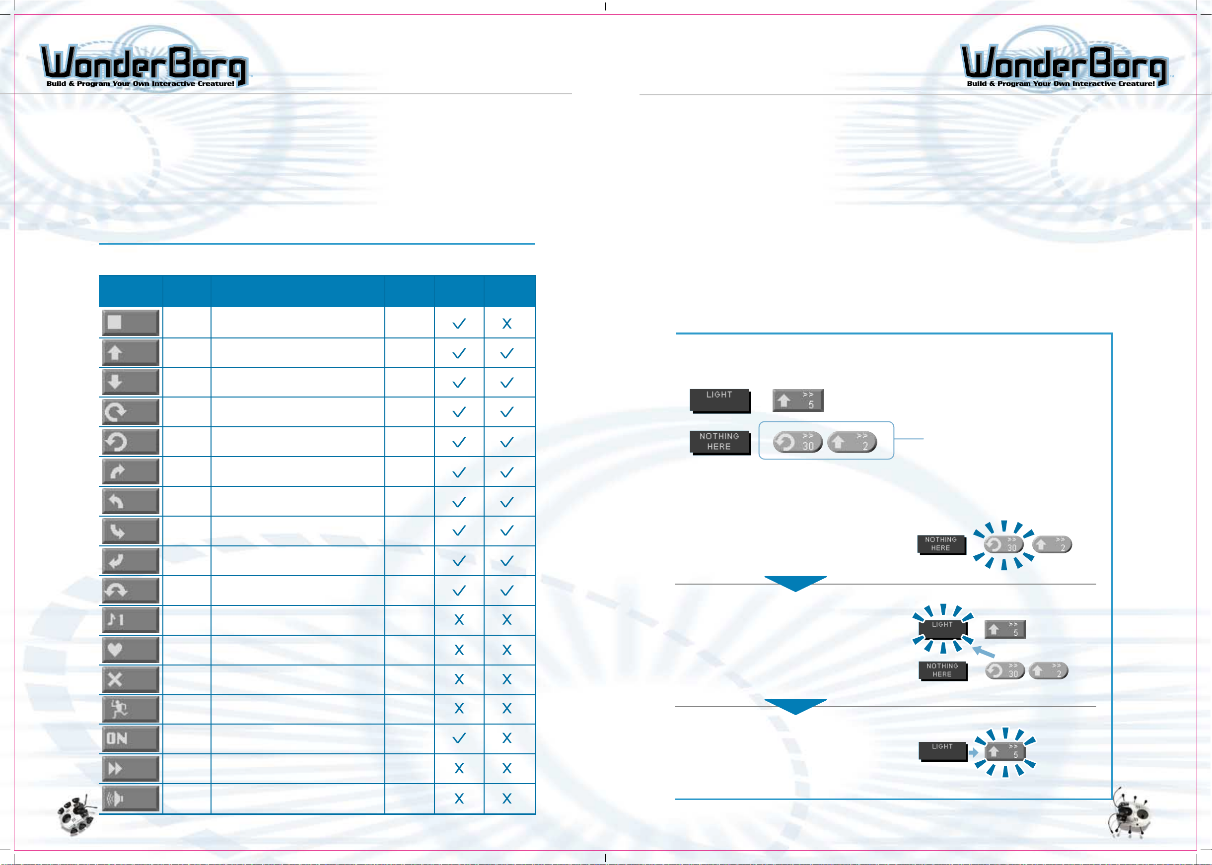
THE COMMAND BLOCK FACTORY PRIORITY ORDER AND INTERRUPTS
Often-Used Commands
Basic Movements The basic movements are those from "Stop" to "Rotate from right to
Switching panels The purpose of switching panels is to switch to a program on another
Command Table This table lists the basic commands, plus other commands, and describes
left" on the command table. The extent of the movement is expressed
in numbers of steps, for example, "Go forward 3 steps" and "Rotate 6
steps to the right". In the case of the "Stop" command, the robot
does not move, but instead of the number of steps, the numerical
parameter for this command gives the number of seconds for which the
robot must stand still.
panel. Commands such as "Switch to Panel 2" can be used. When the
sensor assigned to this command reacts, control switches to the
program on Panel 2.
what they do.
Name Movement time(sec)Icon Override Speed
Stop Robot halts for period specified. time(sec)
Go
forward
Go
backward
Rotate to
the right
Rotate to
the Left
Turn right
Robot advances specified number of steps. Steps
Robot retreats specified number of steps. Steps
Robot moves left and right legs in opposite
directions, and rotates to the right, on
the spot.
Robot moves left and right legs in opposite
directions, and rotates to the left, on
the spot.
Robot turns to the right like a car, by
moving its legs forward on one side only.
Steps
Steps
Steps
Priority Order
When two sensor blocks react at the same time, the sensor block on the higher line of
the program takes priority, and the WonderBorg executes the command linked to that
sensor. If the WonderBorg does not behave as you expect it to, check the priority order.
Interrupt
When you click the "Interrupt" button on the Command Block Factory screen, the selected
block will turn green and its corners will become rounded. When a block is red, other
sensors will be ignored until this block’s command has completed (e.g. until the robot
has advanced 5 steps). When the block is green, however, in the event of a reaction by
a sensor with a higher priority (i.e. a sensor higher up on the Panel screen than the
sensor linked to this command) while this command is being executed, control will switch
to the command assigned to the prioritized sensor. In other words, the green block is
"interruptable". This is explained in the diagram below.
When you use an interrupt, the WonderBorg will react more swiftly to the sensors, and
will break off smoothly in the middle of a series of actions when an interrupt is
triggered.
How an Interrupt Works
Example: If you want to make the WonderBorg walk towards the brightest
direction....
Interruptable block
If a sensor with a higher priority
reacts while action in progress,
control will switch to the command
linked to the prioritized sensor
Turn left
Back Up
right
Back Up
left
Rotate to
the right
or left
Sound
Call a
fellow
WonderBorg
Threaten
fellow
WonderBorg
Dance
Option ON
Switch
panel
Robot turns to the left like a car, by
moving its legs forward on one side only.
Robot turns back to the right like a car,
by moving its legs backward on one
side only.
Robot turns back to the left like a car,
by moving its legs backward on one
side only.
Robot turns randomly either to the right
or to the left.
Robot emits a call - one of the four calls
from 1 to 4 - for the number of times
specified.
While calling, the robot emits the infrared
signal used for calling to another WonderBorg.
While calling, the robot emits the infrared
signal used for threatening another
WonderBorg.
Robot rotates rhythmically to the left and
right.
Motor or other device connected to Option
Connector is turned ON for specified period.
Control jumps to the panel number specified
after the icon (1 to 8).
Period(sec)
Steps
Steps
Steps
Steps
Times
Time(s)
Time(s)
Time(s)
Panel no
1 to 8
If the WonderBorg is programmed to rotate (30 Steps Left), then change position
slightly (go 2 Steps forward).....
1. While the robot is rotating left (for instance,
when it has walked 3 steps).....
2. IF "Light" Sensor reacts, robot does not
have to rotate for remaining number of
steps (nor does it have to take 2 steps
forward in 2nd part of instruction).
"Light" Sensor react!!!
The "Light" sensor is higher up in the
program than "Nothing Here". The first
takes priority.
3. Robot immediately executes "Go Forward 5
Steps" command. ("Go Forward Command"
overrides the other command.)
Tone
(1 to 8)
Robot emits specified tone, which is one
of the 8.
Tone no
1 to 8
4241
Page 23
TRANSMITTING A PROGRAM
TO THE WONDERBORG
Sending a Program to the
WonderBorg
Check that the interface’s main switch is ON. If
it is currently OFF, turn it ON.
Note: The WonderBorg must be in standby mode
(i.e. the green LED should be glowing) before you
start transmitting a program.
Position the WonderBorg so that its head is facing the infrared transmitter on
the interface.
How to position WonderBorg
Main
Switch On
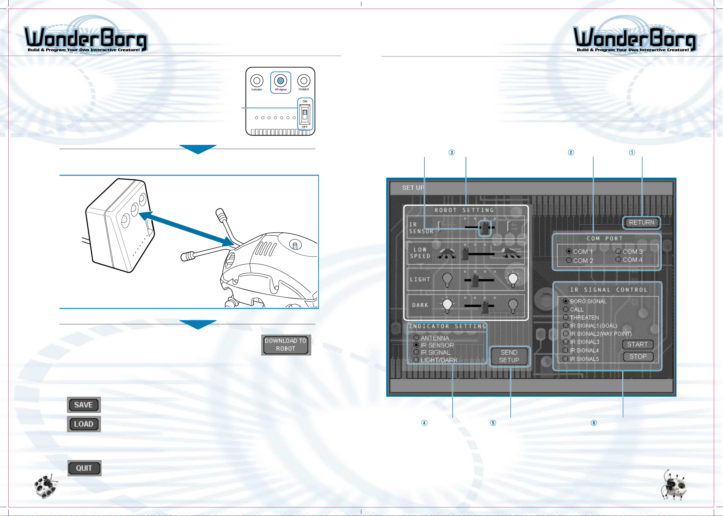
THE SET UP SCREEN
The Set Up Screen
Clicking "Set Up" on the Panel screen will take you to the Settings Screen.
Names of Parts
The names of the parts of the screen are shown below. The numbers correspond to the
numbered descriptions on the following page.
Adjustment knob Robot Settings Set Serial port Return
Not more than 20cm from Interface
without objects in between
Click the "Download to robot" button at the top right of the
Panel screen.
The WonderBorg’s eyes (red LEDs) will flash, and when it
emits a short beep, the transmission is complete.
If the WonderBorg beeps continuously, but is not reacting to anything,
then the transmission has not worked. In this case, repeat the procedure.
Saving a Program
By clicking the "Save" button on the panel screen, you can save your
program to your PC’s hard disk, or to a floppy. Programs previously
saved in this way can be opened on the Panel screen by clicking the
"Load" button.
Exiting from Robot Works
You can close Robot Works by clicking the "Quit" button at the bottom
right of the Panel screen. If you have not already saved the program
you have been working on, the save dialog window will pop up and ask
you whether you want to save the program.
Indicator Setting Send Setup IR Signal Control
4443
Page 24

THE SET UP SCREEN THE SET UP SCREEN
1. Return Go back to Panel screen.
2. Set Serial port: Select the serial port (COM port) to which the Interface
is connected.
3. Robot settings: By moving the adjustment knobs on the screen left or
right, you can set various WonderBorg functions.
The sensitivity of an infrared sensor (corresponding
to a sensor block such as "something in front") has
Infrared
sensor
Low speed
Light
sensor
Dark sensor
four adjustment settings. The closer the adjustment
knob is to the left, the greater the sensitivity and
distance at which objects can be detected.
The exact speed used for "Low speed" has four adjustment
settings. The closer the adjustment knob is to the
left, the slower the speed. ("High speed" has no
adjustment settings.)
A "Light" sensor block can be given any of four settings.
The closer the adjustment knob is to the left, the
weaker the light that will trigger a sensor reaction.
Note: If you set the brightness too low, even normal
indoor light may trigger a sensor reaction.
A "Dark" sensor block can be given any of four setting.
The closer the adjustment knob is to the left, the
stronger the light that will trigger a sensor reaction.
Note: If you set too bright a setting for "Dark", even
normal indoor light may trigger a sensor reaction.
Left LED Right LED
Antennae Left antenna Right antenna
Infrared sensors Left infrared sensor Right infrared sensor
Infrared signals
Lignt and Dark Dark Light
Note: When the floor sensor is OFF, the green LED on the WonderBorg’s back will flash
rapidly.
Reaction triggered by any Infrared signal sent out
by the Interface
5. Send Set Up
When you click this button, the setting on the Set Up screen will be transmitted to
the WonderBorg. Take care to carry out this step, otherwise the changes you have made
to the settings will not be reflected in the WonderBorg’s behavior.
Note: Once the settings have been transmitted, they are saved in the WonderBorg, and
will be retained even when the power is switched to OFF.
6 . IR signal Control
This is used to send a command to the Interface, causing a specific infrared signal to
be transmitted from the Interface to the WinderBorg. If you select the desired infrared
signal and then click "Start", the interface will start transmitting the infrared signal
to the robot. While the transmission is in progress, the red indicator lamp on the
left side of the Interface will flash. If you want to stop the transmission, click
"Stop". The transmission will also stop automatically if you start sending a program
or settings.
4. Indicator This sets the sensors that indicate their reactions via
Settings:
Left LED Right LED
the left and right eyes (red LEDs) while the WonderBorg
is executing a program. This indicates the reaction status
of the sensors, so it is a useful way to check what is
happening in the program.
The LEDs glow while a program is being executed.
By changing the LED settings, you can make the
LEDs flash rapidly when a specified sensor reacts.
Disconnecting the Interface During the Transmission
of an Infrared Signal
If necessary, the Interface can be disconnected from your PC while it is in the
process of transmitting an infrared signal. If you want to do this, unplug the cable,
but leave the main switch ON. It is useful to be able to do this when you want to
place the infrared signal transmitter some distance away from your PC. However,
you must observe the following instructions.
1: Unplug the cable at the Interface side.
Note: Under no circumstances should the special interface Cable be
unplugged at the PC side.
2: Do not turn off the Interface’s main switch (if you do so, the infrared
signal will stop).
3: Do not poke any metal objects into the mouth of the disconnected
cable (this could cause malfunctions).
Note: If you disconnect the Interface from you PC, do not touch the
connector terminal with your fingers or with any metal object.
4645
Page 25
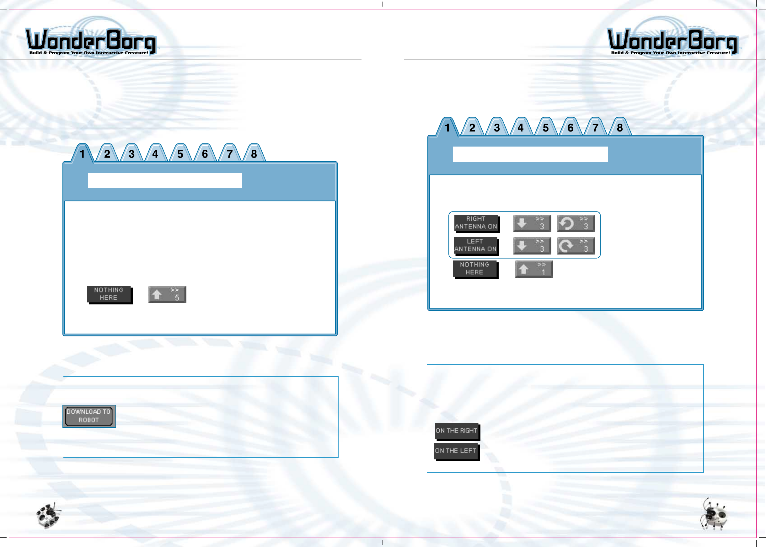
PROGRAMMING: GETTING STARTED PROGRAMMING: GETTING STARTED
Programming Exercises
In this section you will learn how to write programs to make your WonderBorg move.
Exercise 1: Creating a Program that Simply Makes the
Robot Go Forward
We’re now going to program the WonderBorg to continuously walk forward, like toy robots.
Panel 1
Exercise 2: Modifying the Program so that the
WonderBorg can Avoid Obstacles
We’re now going to modify the program from Exercise 1 so that the WonderBorg will use
its touch sensor to detect obstacles, and take evasive action.
Panel 1
Add this section to the program from Exercise 1
If there is no sensor reaction, the WonderBorg will take one step forward. By repeating
this action, it will move forward continuously. Even if its antennae touch something,
it has not been told what to do in this situation, so it will just keep going forward.
Testing
The next step is to send the program to your WonderBorg, and
make it execute the program. Turn the WonderBorg’s POWER switch
ON, place it in front of the Interface, and click the "download
to robot" button at the top right of the Panel screen. If the
WonderBorg gives a short beep, the transmission has been completed
successfully. If you now press the START/STOP button on the
WonderBorg’s back, the robot will start moving. To stop the robot
when it is moving, press the START/STOP button again.
Here, the program for Exercise 1 is augmented with commands to be executed if the
antennae reacts. If the right antenna reacts, the robot is instructed to back up and
rotate to the left, and if the left antenna reacts, to back up and rotate to the
right. If both antennae react at the same time, the upper sensor block takes priority.
In this case, the right antenna is prioritized, so the robot will back up and rotate
to the left.
Testing
It is now time to test the program. By making the WonderBorg execute this program
in various different locations, you will be able to find out what works best in terms
of the number of steps taken when going backward and when turning. You can alter the
numbers in the program very easily by double-clicking the appropriate command block
and then typing in the new number.
Although this program uses the touch sensors, the infrared
sensors can also be used in the same way. Try replacing "right
antenna" with "something on the right", and "left antenna" with
"something on the left". Again, the numbers can be altered very
easily just by double-clicking the appropriate block and typing
in the new number.
4847
Page 26
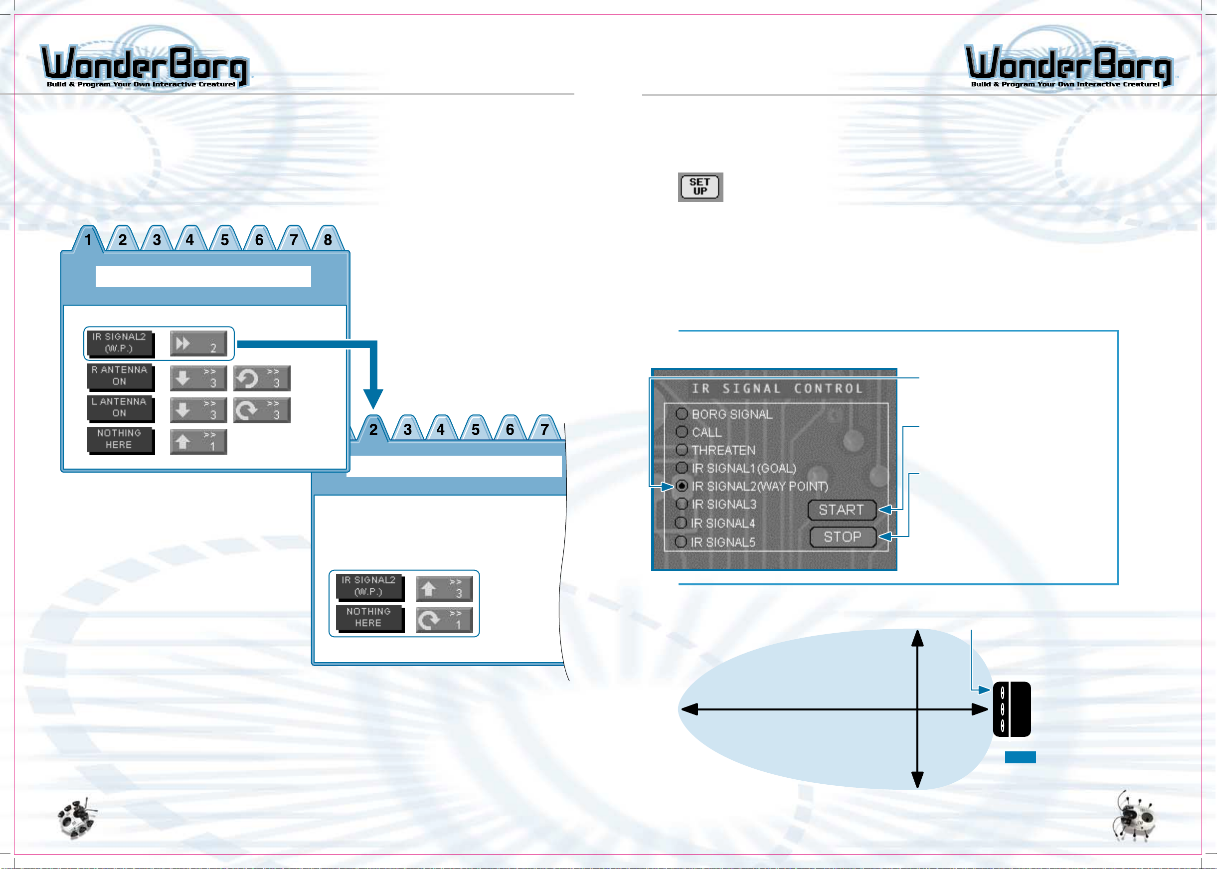
PROGRAMMING: GETTING STARTED PROGRAMMING: GETTING STARTED
Exercise 3: Modifying the Program so that the
WonderBorg can Pick Up and Follow an Infrared Signal
In this exercise, we’re going to modify the program from Exercise 2, so that if the
robot detects an infrared signal, it will enter "Following mode (Panel 2)", and start
following the infrared signal. This program uses 2 panels.
Program for Exercise 3
Panel 1
Add this Section to the program from Exercise 2.
Panel 2
Testing
Before sending the program to the robot and having it executed we are going to prepare
to transmit infrared signal 2 (Guide to another robot) from the interface.
Click the "Set Up" button at the bottom right of the Panel screen, select
"infrared signal 2 (Way Point)" from "IR Signal Control" menu on the
Set UP screen, then click the "Start" button. The red indicator lamp on
the Interface should flash for a short while, then the flashing will
stop, and this pattern should be repeated continuously. If this happens,
the infrared signal 2 is being transmitted from the interface.
If necessary, you can unplug the cable from the Interface, and place
the Interface some distance away from your PC. When you do this, do not
switch the Interface’s main switch OFF: the infrared signal will stop
if you do so.
The range of the infrared signal is shown in the diagram below. Place
the robot somewhere inside this range before starting the transmission.
If the transmission does not work, move the robot a little closer to
the Interface, then try again.
How to Transmit an Infrared Signal
1. Select the desired Signal by
clicking the name.
Create a new panel: Panel 2
You can simply copy the blocks
from Panel 1 to Panel 2, and then
edit them.
Panel 1
Panel 1 was created by taking the program from Exercise 2 and augmenting it with a
line telling the robot what to do if it detects infrared signal 2 (Way Point). If it
detects this particular infrared signal, it is instructed to switch to the program on
Panel 2. As a result of the tests you carried out in Exercise 2, your blocks for evasive
action may look different from those shown above, but you do not need to alter the
figures all over again.
2. When you click the "Start" button,
the infrared signal will be transmitted
to the robot.
3. To stop the transmission of the
infrared signal, either click the
"Stop" button, or start transmitting
another signal. The transmission
will also stop automatically if
you click "Download to WonderBorg"
on the Settings screen, if you
transmit a program by clicking
"Download to WonderBorg" on the
Panel screen.
The Ranged Reached by the Infrared Signal
Interface (front face)
max 1.5m
max 0.75m
Panel 2
Panel 2 contains a program for "Following mode", where the robot will follow infrared
signal 2 (Way Point). If it detects this particular infrared signal, it is instructed
to move forward 3 steps. If there is no sensor reaction, it must then turn one step
to the right. In this program, if the robot loses the infrared signal, it will turn
round and round, while if it finds it, it will move forward.
Range reached by signal
Note: The range may vary
depending on the
brightness of the
surroundings, and other
factors.
5049
Page 27

PROGRAMMING: GETTING STARTED
Exercise 4: Modifying the Program to Make the
WonderBorg Follow an infrared Signal Reliably
In this exercise, we are going to take the program on Panel 2 from Exercise 3, and
modify it, using the "interrupt" function, so that the WonderBorg will follow infrared
signal 2 (Way Point) more reliably.
With the program from Exercise 3, when the WonderBorg has detected infrared signal 2
(Way Point) and is walking towards the signal, if an empty can or other obstacle is
placed between the robot and the Interface, blocking the signal, then the robot will
lose the signal and end up turning round and round on the spot. With this new program,
however, the robot moves forward a little each time it more or less completes a full
turn if it loses the signal, it should be able to find it again.
In the new program on Panel 2, if there is no sensor reaction, the WonderBorg turns
18 steps to the right, and then goes 5 steps forward. This means that it is repeating
a behavior pattern of scanning its surroundings, and then changing its position slightly.
The blocks for these actions are green overridable blocks, so if the sensor for infrared
signal 2 is triggered while the rotating, it will stop rotation and start walking
forward.
SOFTWARE LICENSE AGREEMENT
This software license agreement ("Agreement") is a legal contract between a user ("User"),
and Bandai Co., Ltd. ("Bandai") pertaining to the Robotworks Software ("Software"). The Software
is intended for use on a personal computer and is included with the product known as
WonderBorg("Product").
By opening the CD-ROM containing the Software or by using the Software, the User shall be
deemed to have agreed to all the provisions of the Agreement. The User is requested to open
the package or to use the Software only if he or she agrees to be bound by the provisions of
the Agreement.
Clause 1: Intellectual Property Right
As between User and Bandai, any and all patents, copyrights, design rights, trademarks, trade
secrets, and any other intellectual property rights in the Software, Products and supporting
materials, including user manuals, are owned by Bandai.
Clause 2: Licensing
Bandai grants to the User who purchases the Software, a non-exclusive right to use the Software
in accordance with the provisions of this Agreement. The CD-ROM containing the Software
accompanying the Products is supplied to the User, but this does not constitute a transfer of
ownership of the Software.
Panel 1
Panel 2
Clause 3: Restrictions
1. The User shall use the Software and supporting materials in accordance with the terms
of this Agreement.
2. The User may not create a copy of the Software and its user manual, in whole or in part,
without permission, provided that the User may create one copy of the Software only for
backup purpose.
3. The User may not install the Software on more than one computer, and may not allow the
Software to be used by a third party.
4. The User may not lend or sell the Software to a third party.
5. The User agrees to not modify, adapt, translate, reverse engineer, decompile, or otherwise
attempt to discover the source code of the Software.
Clause 4: Transfer of Ownership of the Software
The User may transfer the right to use the Software, granted by the Agreement, to a third
party only if all the following conditions are met:
1. The User must transfer ownership of the Product, including the Agreement, a copy of the
Software, and all supporting materials, and must retain absolutely no ownership of the
foregoing.
2. The transferee agrees to be bound and restricted by the Agreement for the use of the
Software.
Clause 5: Exemption from Liability
1. The Software is being delivered "As IS". Bandai provides absolutely no guarantee with
respect to the Software. Any problems arising in regard to the use of the Software shall
be deemed to be the responsibility of the User and shall be solved at the User s expense.
2. The specifications for the Software and the Product and the contents of the supporting
materials may be changed without prior notice.
3. Bandai shall bear absolutely no responsibility or liability for any damages, loss or
injury resulting from the use of the Software, the Product or supporting materials.
Pre-Programmed Personalities
As a user you may opt to use the three pre-programmed personalities included in the
software. These are three completed programs that you can download to your WonderBorg.
You may want to try these out initially to become more familiar with programming the
WonderBorg.
The Adult personality is the most advanced pre-programmed personality. It uses the
full range of its sensors.
The Baby personality does not use as many of its sensors as the adult. It hesitates
and makes noises before it advances forward. The baby personality also dances around
when it sees darkness (when you put your finger over the light sensor window).
The Dark personality is always looking for a fight. It will stay at a stand still and
use a threatening tone to try and challenge other Borgs. It uses a wide range of its
senses.
To access these personalities, open up the Robot Works program. Left mouse click on
Load. Select the "Personality" folder. Pick which personality you wish to open, click
on it and press open.
Clause 6: Compensation for Damage
In the event that the User inflicts damage on Bandai by infringing any of the provisions of
the Agreement, Bandai may take legal action against the User or seek compensation.
Clause 7: Export Restrictions
The User may not export the Software and copies of the Software to the Japan, Hong Kong, Taiwan,
China, Australia, New Zealand, and other countries in the Asia Pacific.
"WonderBorg" and "Robotworks" are the trademarks of Bandai.
"Windows ME" "Windows 98" and "Windows 95" are registered trademarks or trademarks of Microsoft
Corporation..
Other names of companies or products are, in general, trademarks or registered trademarks of
the respective companies.
5251
Page 28

TROUBLESHOOTING
TROUBLESHOOTING
Troubleshooting Problems with Program Transmission
- If you transmit a program, and then find that the WonderBorg still behaves as it
Operating Problems
- If the WonderBorg does not beep when the power is turned ON:
Check that the motherboard and motor units are properly connected.
- If nothing happens when the power is switched ON:
If you have previously opened the motor unit to change the gears, check whether
you have done this correctly. Check that the batteries have been inserted,
and that they are the right way.
did before:
The WonderBorg cannot receive a program while the green LED is flashing. Check
that the WonderBorg and the Interface are facing one another, and are close
enough. If they are too far apart, or if there is an object between them, it
will not be possible to transmit the program. The WonderBorg’s infrared receiver
shouldn’t be more than 20cm away from the Interface, and there should be nothing
in the way between the two. Is someone using another WonderBorg close by? If
so, this may make it impossible to transmit programs to your own WonderBorg.
Are you using the robot in an extremely bright location? This can make it
impossible to transmit programs to your WonderBorg.
- If the WonderBorg does not move correctly when you transmit
a program:
Check whether something is blocking the signal between the Interface transmitter
and the WonderBorg’s infrared receiver. Check that the interface and the robots
are far enough apart.
- If the WonderBorg makes a chirping noise while executing a
program, and the stops moving:
Check whether the robot’s leg has been caught somehow. If any of its legs are
interfered with while it is executing a program, the WonderBorg will
chirp repeatedly.
- If the WonderBorg's legs start trembling when the power is
switched ON:
This is not a fault: the WonderBorg is performing its initial operation check.
Just leave it alone for a short while.
- If the WonderBorg goes backward when the program says it should
to forward:
Check whether the motherboard and the motor units have been connected the
wrong way.
- If the WonderBorg does not walk properly:
Check that the legs have been assembled correctly. To make the robot walk
efficiently, the legs have to be assembled at the optimum angle. If you are
using the legs made of plastic-covered wire, check that they are bent correctly.
- If the WonderBorg starts executing the program, and then stops
after a short while:
check the batteries. When the batteries are low, the WonderBorg will sometimes
come to a standstill when executing a movement at the "low speed" setting. If
this is the problem, change the batteries.
- If the Interface is not showing any reaction:
Check that the cable is properly connected. Push it in as far as it will go.
Is the port setting correct?
Consult you PC manual and make sure the port selected is the one to which the
Interface is connected. Is the interface switched ON? Check that the green
indicator lamp is glowing. If the interface is switched ON but the green indicator
lamp is not glowing, check that the batteries are inserted the right way.
It can happen that a scrap of plastic from the battery wrapper has gotten stuck
over a battery contact, so check for this too.
- If an error message appears on your PC screen:
An error message may appear if you select a port other than the one the Interface
is connected to. In this case, the message will disqppear when you click "OK"
on the message dialog window, and you can then select the correct port. In
this case, the cursor will turn in to an hourglass shape, but it will still
work when you click it. Have you select the correct port? Consult your PC
manual and select the port to which the interface is connected.
- If your PC crashes:
Restart your PC.
Have you selected the correct port? Consult you PC manual and select the port
to which the interface is connected.
A. If the program is transmitted successfully: the WonderBorg gives a short beep.
B. If the program is not updated: the WonderBorg gives a long beep
C. If a faulty program has been received: the WonderBorg gives three long beeps.
Problems with Sensors
- If the touch sensors are not reacting properly:
Check whether one of the sensors has come loose from the rubber socket holding
it in place. You will need to remove the body shell. If you are using the
antennae made of plastic-covered wire, check that they are bent correctly.
- If the infrared sensors are not reacting properly:
Go into the Set Up screen and adjust the sensitivity using the "Infrared
sensors" gauge.
- If the Light sensor is not reacting properly:
Adjust the sensitivity using the "Light sensor" gauge on the Set Up screen.
When programming, bear in mind that at certain levels of brightness, the
WonderBorg cannot distinguish between "Light" and "Dark".
- If the floor sensor’ "OFF" reaction is triggered while the WonderBorg is walking:
Check whether the WonderBorg’s body is tilted because it has stepped up on
some obstacle, or because of the way its legs are bent. Marked tilting of
the body can sometimes make the floor sensors lose track of the floor.
If the floor is black (or very dark in color), the floor sensors will be unable
to detect the floor.
(Hint: the speed of the flashing green LED indicates the type of floor surface
(Light / Dark) as sensed by the WonderBorg - In addition, make good use of
the Interrupt function)
- If the floor sensors are not reacting properly:
The performance of the floor sensors may vary slightly from one WonderBorg
to another. Go into the Set Up screen and adjust the sensitivity, using the
"infrared sensors" gauge. When programming, it should also be kept in mind
that at certain "Floor status" settings, the robot may be unable to distinguish
between "Floor sensor ON" and "Floor sensor OFF".
- If the infrared sensors and the floor sensors are not working:
If you are using the WonderBorg in a very light or brightly-lit location, the
obstacle sensors and floor sensors may not react.
- If the infrared sensors and the floor sensors have become less effective:
Check the batteries: when the batteries run down, the sensors effective range
shrinks. If this is the problem, change the batteries.
- If the WonderBorg will no longer move forward (or carry out some other action in
question) even though none of the sensors is reacting:
Are the blocks "Nothing Here" and "Advance" (or the other action in question)
waiting for a condition specified in a line higher up the panel? If sensor
are reacting less effectively than before:
Check whether you have set the number of steps in the command block to more
than 2. While the WonderBorg is executing a command block, it cannot react
to any other sensor block, so care is needed when the number of spaces in
the command block is set to a number higher than 2 (i.e. when a single command
block takes some time to execute). If you want a sensor with a higher priority
to be able to take effect during the execution of a block involving more than
2 steps, you will need to specify the command block in question as "Interrupt".
Again, if you want to speed up the reaction of the sensor even when the command
block does not contain more than 2 steps, you should specify the command block
as "Interrupt".
5453
Page 29
WARRANTY
APPENDIX
25
90-Day Limited Warranty
Tiger Electronics (Tiger) warrants to the original consumer purchaser of this product
that the product will be free from defects in materials or workmanship for 90 days
from the date of original purchase. This warranty does not cover damages resulting from
accident, negligence, improper service or use, or other causes not arising out of defects
in materials or workmanship.
During this 90-day warranty period, the product will either be repaired or replaced
(at Tiger’s option) without charge to the purchaser, when returned with proof of the
date of purchase to either the dealer or to Tiger.
Product returned to Tiger without proof of the date of purchase or after the 90-day
warranty period has expired, but prior to one year from the original date of purchase,
will be repaired or replaced (at Tiger’s option) for a service fee of U.S.$ 66.00
Payments must be by check or money order payable to Tiger Electronics.
The foregoing states the purchaser’s sole and exclusive remedy for any breach of warranty
with respect to the product.
All product returned must be shipped prepaid and insured for loss or damage to:
Tiger Electronics Ltd. Repair Dept.
1000 N. Butterfield Road, Unit 1023
Vernon Hills, Illinois 60061, U.S.A.
The product should be carefully packed in the original box or other packing materials
sufficient to avoid damage during shipment. Include a complete written description of
the defect, a check if product is beyond the
90-day warranty period, and your printed name, address and telephone number.
Template for Legs and Antennae
Just place your WonderBorg on this paper cover, and then
bend the legs and antennae to match the picture!
20
15
THIS WARRANTY IS IN LIEU OF ALL OTHER WARRANTIES AND NO OTHER REPRESENTATIONS OR CLAIMS
OF ANY NATURE SHALL BE BINDING ON OR OBLIGATE TIGER IN ANY WAY. ANY IMPLIED WARRANTIES
APPLICABLE TO THIS PRODUCT, INCLUDING WARRANTIES OF MERCHANTABILITY AND FITNESS FOR A
PARTICULAR PURPOSE, ARE LIMITED TO THE NINETY (90) DAY PERIOD DESCRIBED ABOVE. IN NO
EVENT WILL TIGER BE LIABLE FOR ANY SPECIAL, INCIDENTAL, OR CONSEQUENTIAL DAMAGES RESULTING
FROM POSSESSION, USE, OR MALFUNCTION OF THIS TIGER PRODUCT.
Some states do not allow limitations as to how long an implied warranty lasts and/or
exclusions or limitations of incidental or consequential damages, so the above limitations
and/or exclusions of liability may not apply to you. This warranty gives you specific
rights, and you may also have other rights which vary from state to state.
For more information about Tiger Electronics, our products and special promotions, please
visit our web site at: www.tigertoys.com
PLACE WONDERBORG HERE.
10
9
8
7
6
5
4
3
2
1
0
Note:
Before adjusting the legs, switch the power O N .
5655
Page 30

FCC STATEMENT
This device complies with Part 15 of the FCC Rules. Operation is subject
to the following two conditions :
(1) this device may not cause harmful interference, and (2) this device
must accept any interference received, including interference that may cause
undesired operation.
Warning: Changes or modifications to this unit not expressly approved by
the party responsible for compliance could void the user’s authority to
operate the equipment.
NOTE: This equipment has been tested and found to comply with the limits
for a Class B digital device, pursuant to Part 15 of the FCC Rules. These
limits are designed to provide reasonable protection against harmful
interference in a residential installation. This equipment generates, uses,
and can radiate radio frequency energy and, if not installed and used in
accordance with the instructions, may cause harmful interference to radio
communications. However, there is no guarantee that interference will not
occur in a particular installation. If this equipment does cause harmful
interference to radio or television reception, which can be determined by
turning the equipment off and on, the user is encouraged to try to correct
the interference by one or more of the following measures:
- Reorient or relocate the receiving antenna.
- Increase the separation between the equipment and receiver.
- Connect the equipment into an outlet on a circuit different from that
to which the receiver is connected.
- Consult the dealer or an experienced radio TV technician for help.
5857
 Loading...