

Page 1

BENGAL BRUTE
Current as of 01/30/2012
ASSEMBLIES
JD 62-6420
CAB
P A RTS LISTING WITH
MOUNTING AND OPERATING
INSTRUCTIONS
Tiger Corporation
3301 N. Louise Ave.
Sioux Falls, SD 57107
1-800-843-6849
1-605-336-7900
www.tiger-mowers.com
06011000
Page 2

TO THE OWNER / OPERATOR / DEALER
All implements with moving parts are potentially hazardous. There is no substitute for a cautious,
safe-minded operator who recognizes the potential hazards and follows reasonable safety practices.
The manufacturer has designed this implement to be used with all its safety equipment properly attached to minimize the chance of accidents.
BEFORE YOU START!! Read the safety messages on the implement and shown in this manual.
Observe the rules of safety and use common sense!
READ AND UNDERSTAND THIS MANUAL! Non–English speaking operators will need to GET
THE MANUAL TRANSLATED as needed!
W arranty Information: Read and understand the complete W arranty Statement found in this manual. Fill out the
W arranty Registration form in full and return it within 90 days. Make certain the Serial Number of the machine is
recorded on the W arranty Card, and form that you retain.
Page 3

FORWARD
This manual contains information about many features of the T iger mowing
and roadside maintenance equipment. Some of these include: Safety precautions,
Assembly instructions, Operations, Maintenance and Parts. This manual will also
assist you in the proper break-in, daily care, andtroubleshooting of your new
mower .
We recommend that you read carefully the entire manual before operating the
unit. Also, time spent in becoming fully acquainted with its performance features,
adjustments, and maintenance schedules will be repaid in a long and satisfactory
life of the equipment.
T roubleshooting - Please, before you call, help us to help you!
Please look at the equipment to observe what is happening, then:
• Classify the problem
• Hydraulic, electrical or mechanical - Read the trouble shooting section
• Tractor or T ruck chassis - Contact vehicle dealer
• If unable to correct the problem yourself, contact your local Tiger Dealer af ter
gathering:
• Machine model _______________________
• Serial number ________________________
• Dealer name _________________________
• Detailed information about the problem including results of troubleshooting
Attention Owner / Operator / Dealer: It is your obligation to read, and understand,
the warranty information section located at the back of this manual denoting that the
purchaser understands the safety issues relating to this machine and has received
and will read a copy of this manual.
If at any time, you have a service problem with your Tiger mower , Contact
your local dealer for service and parts needed.
MANUF ACTURED BY: DISTRIBUTED BY :
Tiger Corporation _____________________
3301 N. Louise Ave. _____________________
Sioux Falls, SD 57107 1-_____-_____-________
1-800-843-6849 1-_____-_____-________
1-605-336-7900
www .tiger-mowers.com
Page 4

Page 5

T ABLE OF CONTENTS
SAFETY SECTION_____________________________________ 1
ASSEMBLY / MOUNTING SECTION______________________ 2
OPERATION SECTION_________________________________ 3
MAINTENANCE SECTION______________________________ 4
P ARTS SECTION______________________________________ 5
COMMON PARTS SECTION____________________________ 6
WARRANTY INFORMA TION_____________________________ 7
This symbol means:
CAUTION – YOUR SAFETY IS AT RISK!
When you see this symbol, read and
follow the associated instructions carefully
or personal injury or damage may result.
Tiger is a registered trademark.
Page 6

Page 7

SAFETY
SECTION
Safety Section 1-1
Page 8

SAFETY
A safe and careful operator is the best operator. Safety is of
primary importance to the manufacturer and should be to the owner /
operator. Most accidents can be avoided by being aware of your
equipment, your surroundings, and observing certain precautions.
The first section of this manual includes a list of Safety Messages that,
if followed, will help protect the operator and bystanders from injury
or death. Read and understand these Safety Messages before
assembling, operating or servicing this mower. This equipment
should only be operated by those persons who have read the Manual,
who are responsible and trained, and who know how to do so safely
and responsibly.
The Safety Alert Symbol combined with a Signal Word, as seen below, is
used throughout this manual and on decals which are attached to the
equipment. The Safety Alert Symbol means: “ATTENTION! BECOME
ALERT! YOUR SAFETY IS INVOLVED!” The symbol and signal word are
intended to warn the owner / operator of impending hazards and the degree
of possible injury when operating this equipment.
Practice all usual and customary safe working precautions and
above all -- remember safety is up to YOU! Only YOU can
prevent serious injury or death from unsafe practices.
This is the Safety Alert Symbol. When you see this symbol on your machine or in
these instructions, be alert to the potential for personal injury .
The lowest level of Safety Message; warns of possible injury. Decals located on the
equipment with this signal word are Black and Yellow.
Serious injury or possible death! Decals are Black and Orange.
Imminent death / critical injury . Decals are Red and White.
READ, UNDERSTAND, and FOLLOW the following Safety
Messages. Serious injury or death may occur unless care is taken to follow
the warnings and instructions stated in the Safety Messages. Always use
good common sense to avoid hazards. (SG-2)
Safety Section 1-2
Page 9
SAFETY
PELIGRO!
DANGER!
WARNING!
WARNING!
Si no lee Ingles, pida ayuda a alguien que
si lo lea para que le traduzca las medidas
de seguridad. (SG-3)
Never operate the Tractor or Implement until you have read and
completely understand this Manual, the Tractor Operator’s Manual,
and each of the Safety Messages found in the Manual or on the Tractor
and Implement. Learn how to stop the tractor engine suddenly in an
emergency. Never allow inexperienced or untrained personnel to
operate the Tractor and Implement without supervision. Make sure
the operator has fully read and understood the manuals prior to
operation. (SG-4)
Always maintain the safety decals in good readable condition. If the
decals are missing, damaged, or unreadable, obtain and install replacement decals immediately. (SG-5)
Make certain that the “Slow Moving Vehicle” (SMV) sign is installed in
such a way as to be clearly visible and legible. When transporting the
Equipment use the Tractor flashing warning lights and follow all local traffic
regulations. (SG-6)
!
LEA EL
INSTRUCTIVO!
WARNING!
WARNING!
DANGER!
Operate this Equipment only with a Tractor equipped with an
approved roll-over-protective system (ROPS). Always wear seat
belts. Serious injury or even death could result from falling off the
tractor--particularly during a turnover when the operator could be
pinned under the ROPS. (SG-7)
Do not modify or alter this Implement. Do not permit anyone to modify
or alter this Implement, any of its components or any Implement
function. (SG-8)
BEFORE leaving the tractor seat, always engage the brake and/or set
the tractor transmission in parking gear, disengage the PTO, stop the
engine, remove the key, and wait for all moving parts to stop. Place the
tractor shift lever into a low range or parking gear to prevent the tractor
from rolling. Never dismount a Tractor that is moving or while the engine
is running. Operate the Tractor controls from the tractor seat only.
(SG-9)
Safety Section 1-3
Page 10
SAFETY
DANGER!
DANGER!
WARNING!
DANGER!
Never allow children or other persons to ride on the Tractor or Implement.
Falling off can result in serious injury or death.
(SG-10)
Never allow children to operate or ride on the Tractor or Implement.
(SG-11)
Do not mount the Tractor while the tractor is moving. Mount the
Tractor only when the Tractor and all moving parts are completely
stopped. (SG-
12)
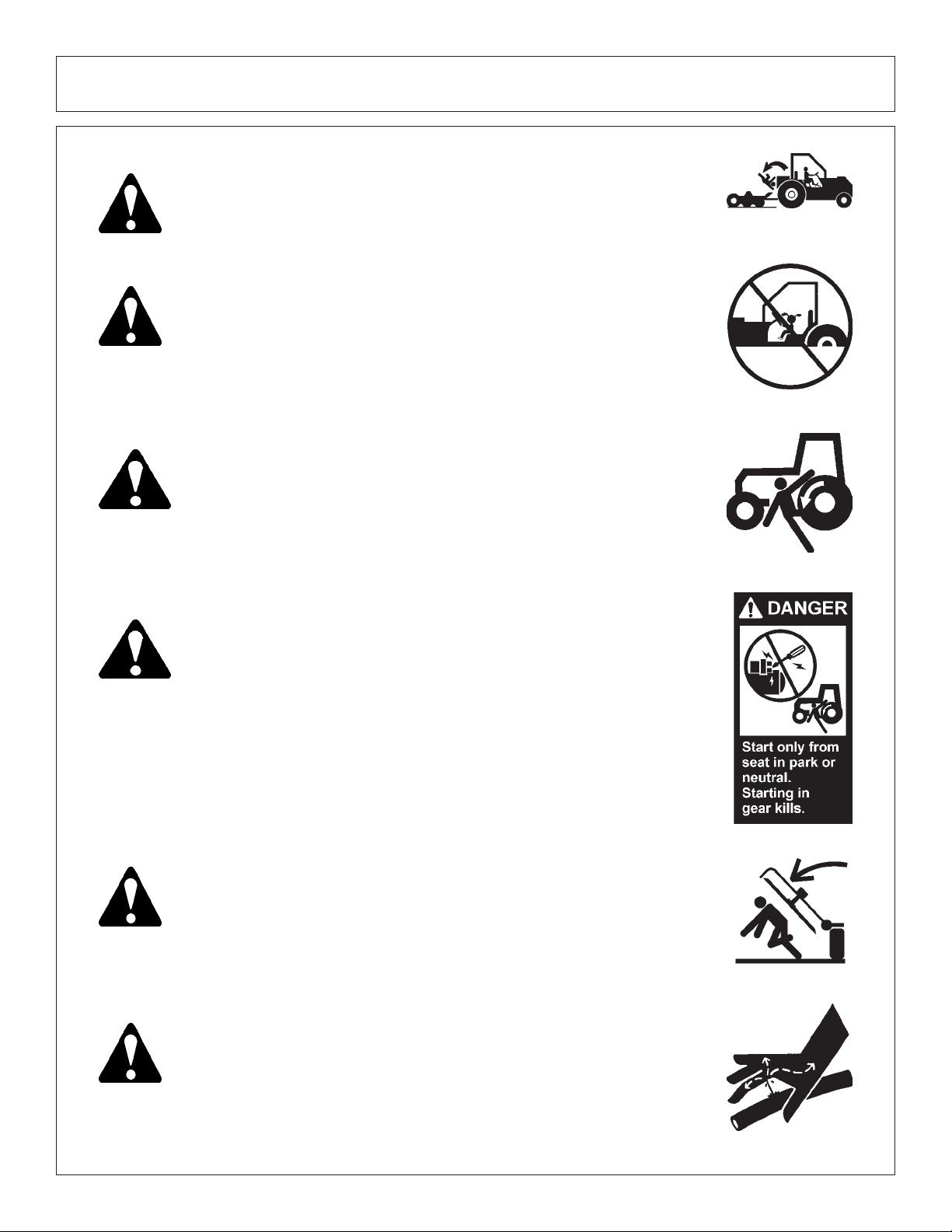
Start tractor only when properly seated in the Tractor seat. Starting a
tractor in gear can result in injury or death. Read the Tractor operators
manual for proper starting instructions. (SG-13)
DANGER!
Never work under the Implement, the framework, or any lifted component unless the Implement is securely supported or blocked up to
prevent sudden or inadvertent falling which could cause serious injury
or even death. (SG-14)
DANGER! Do not operate this Equipment with hydraulic oil leaking. Oil is
expensive and its presence could present a hazard. Do not check for
leaks with your hand! Use a piece of heavy paper or cardboard. Highpressure oil streams from breaks in the line could penetrate the skin
and cause tissue damage including gangrene. If oil does penetrate the
skin, have the injury treated immediately by a physician knowledgeable and skilled in this procedure. (SG-15)
Safety Section 1-4
Page 11
SAFETY
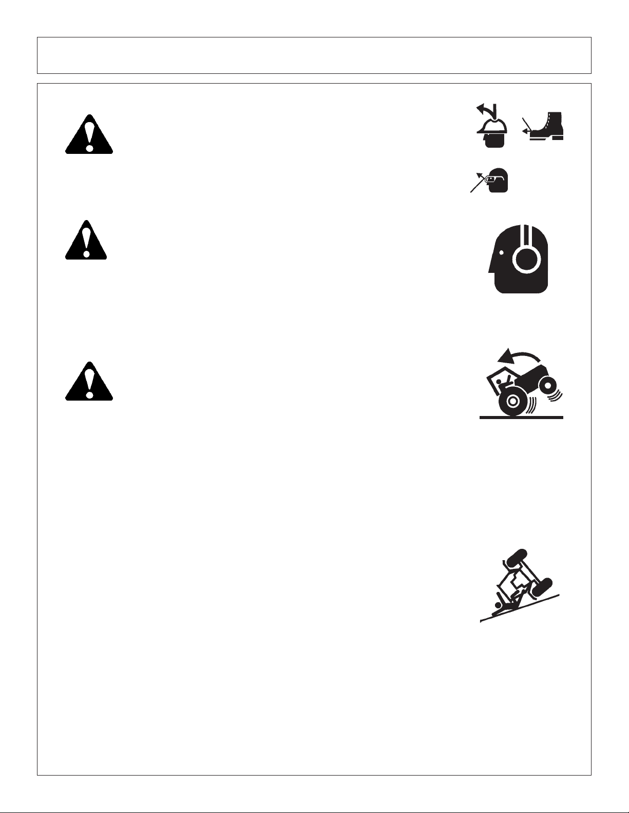
WARNING! The operator and all support personnel should wear hard hats,
safety shoes, safety glasses, and proper hearing protection at all
times for protection from injury including injury from items thrown by
the equipment. (SG-16)
CAUTION!
WARNING!
PROLONGED EXPOSURE TO LOUD NOISE MAY CAUSE PERMANENT HEARING LOSS! Tractors with or without an Implement at-
tached can often be noisy enough to cause permanent hearing loss.
We recommend that you always wear hearing protection if the noise in
the Operator’s position exceeds 80db. Noise over 85db over an
extended period of time will cause severe hearing loss. Noise over 90db
adjacent to the Operator over an extended period of time will cause
permanent or total hearing loss. Note: Hearing loss from loud noise
[from tractors, chain saws, radios, and other such sources close to the
ear] is cumulative over a lifetime without hope of natural recovery. (SG-I7)
Transport only at safe speeds. Serious accidents and injuries
can result from operating this equipment at unsafe speeds.
Understand the T ractor and Implement and how it handles before
transporting on streets and highways. Make sure the Tractor
steering and brakes are in good condition and operate properly .
Before transporting the Tractor and Implement, determine
the safe transport speeds for you and the equipment.
Make
sure you abide by the following rules:
1.
T est the tractor at a slow speed and increase the speed slowly.
Apply the Brakes smoothly to determine the stopping characteristics
of the Tractor and Implement. As you increase the speed of the
Tractor the stopping distance increases. Determine the maximum
safe transport speed for you and this Equipment.
Test the equipment at a slow speed in turns. Increase the speed
2.
through the turn only after you determine that it is safe to operate
at a higher speed. Use extreme care and reduce your speed
when turning sharply to prevent the tractor and implement from
turning over. Determine the maximum safe turning speed for you
and this equipment before operating on roads or uneven ground.
Only transport the Tractor and Implement at the speeds that you
3.
have determined are safe and which allow you to properly
control the equipment.
Be aware of the operating conditions. Do not operate the Tractor
with weak or faulty brakes. When operating down a hill or on wet
or rain slick roads, the braking distance increases: use extreme
care and reduce your speed. When operating in traffic always use
the Tractor’s flashing warning lights and reduce your speed. Be
aware of traffic around you and watch out for the other guy. (SG-19)
Safety Section 1-5
Page 12
SAFETY
WARNING! Never attempt to lubricate, adjust, or remove material from the
Implement while it is in motion or while tractor engine is running. Make
sure the tractor engine is off before working on the Implement.
(SG-20)
WARNING!
WARNING!
DANGER!
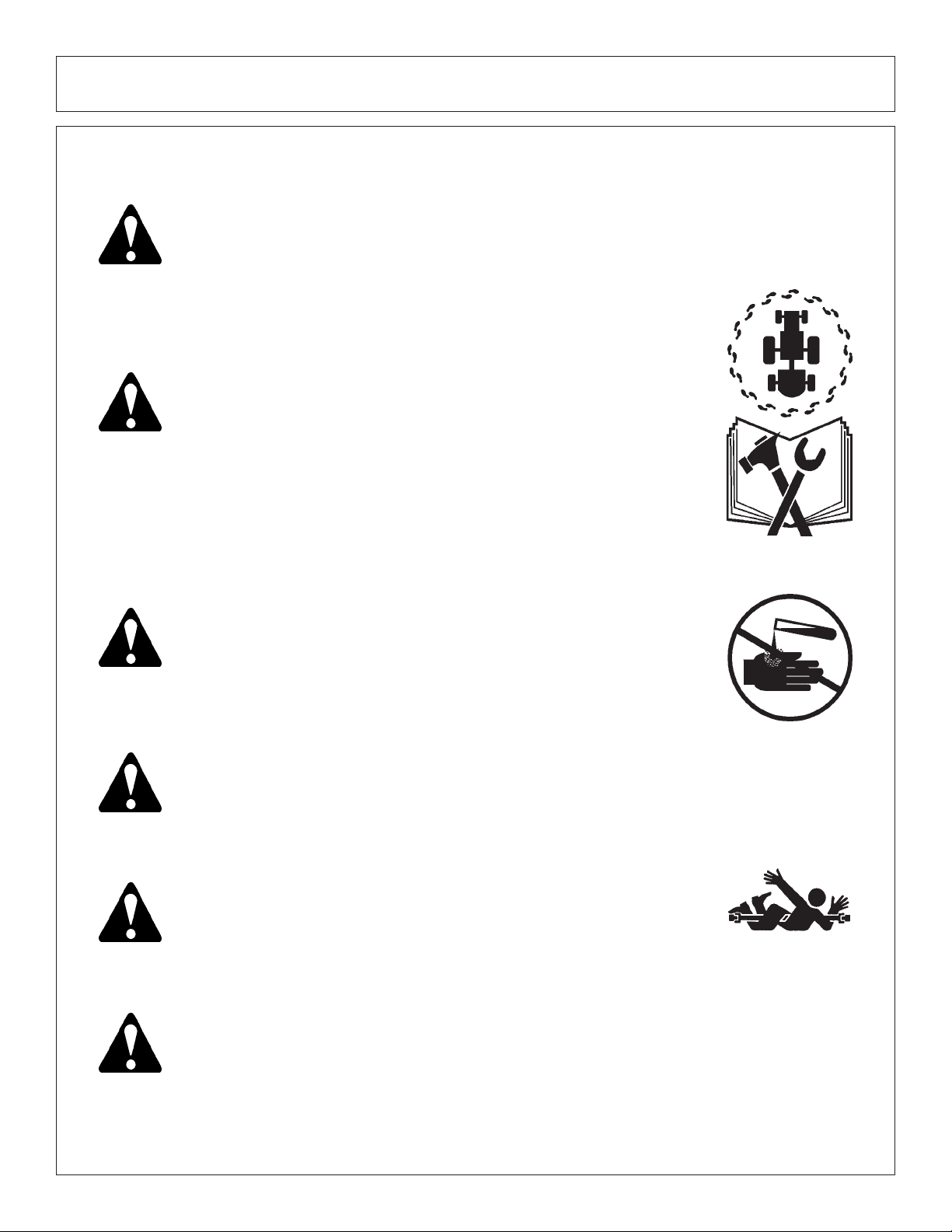
Periodically inspect all moving parts for wear and replace when
necessary with authorized service parts. Look for loose fasteners,
worn or broken parts, and leaky or loose fittings. Make sure all pins
are properly secured. Serious injury may occur from not maintaining
this machine in good working order. (SG-21)
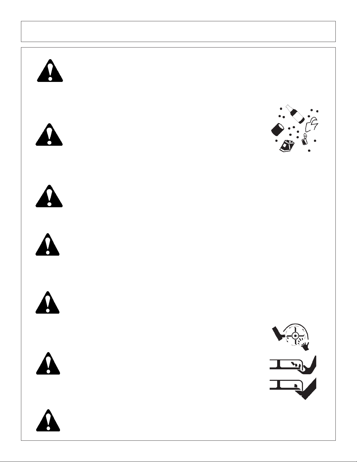
Always read carefully and comply fully with the manufacturers instructions when handling oil, solvents, cleansers, and any other chemical
agent. (SG-22)
Never run the tractor engine in a closed building or without adequate
ventilation. The exhaust fumes can be hazardous to your health.
(SG-23)
DANGER!
DANGER!
KEEP AWAY FROM ROTATING ELEMENTS to prevent entanglement
and possible serious injury or death. (SG-24)
Never allow children to play on or around Tractor or Implement. Children
can slip or fall off the Equipment and be injured or killed. Children can
cause the Implement to shift or fall crushing themselves or others. (SG-25)
Safety Section 1-6
Page 13

SAFETY
DANGER!
DANGER! Operate the Tractor and/or Implement controls only while properly seated
WARNING!
NEVER use drugs or alcohol immediately before or while operating the
Tractor and Implement. Drugs and alcohol will affect an operator’s
alertness and coordination and therefore affect the operator’s ability to
operate the equipment safely. Before operating the Tractor or Implement, an operator on prescription or over-the-counter medication must
consult a medical professional regarding any side effects of the medication that would hinder their ability to operate the Equipment safely.
NEVER knowingly allow anyone to operate this equipment when their
alertness or coordination is impaired. Serious injury or death to the
operator or others could result if the operator is under the influence of
drugs or alcohol. (SG-27)
in the Tractor seat with the seat belt securely fastened around you.
Inadvertent movement of the Tractor or Implement may cause serious
injury or death. (SG-29)
Mow only in conditions where you have clear visibility in daylight or with
adequate artificial lighting. Never mow in darkness or foggy conditions
where you cannot clearly see at least 100 yards in front and to the sides of
the tractor and mower. Make sure that you can clearly see and identify
passersby, steep slopes, ditches, drop-offs, overhead obstructions, power
lines, debris and foreign objects. If you are unable to clearly see this type
of items discontinue mowing. (SGM-1)
DANGER!
DANGER! All Safety Shields, Guards and Safety devices including
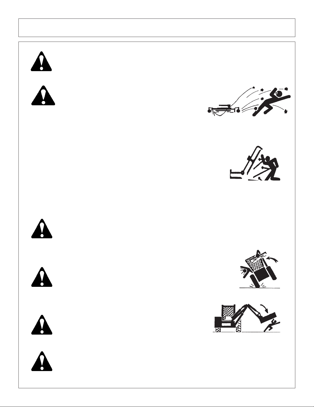
There are obvious and hidden potential hazards in the operation of this
Mower. REMEMBER! This machine is often operated in heavy brush
and in heavy weeds. The Blades of this Mower can throw objects if
shields are not properly installed and maintained. Serious injury or
even death may occur unless care is taken to insure the safety of the
operator, bystanders, or passersby in the area. Do not operate this
machine with anyone in the immediate area. Stop mowing if anyone
is within 100 yards of mower. (SGM-2)
(but not limited to) - the Deflectors, Chain Guards, Steel
Guards, Gearbox Shields, PTO integral shields , and
Retractable Door Shields should be used and maintained in good working condition. All safety devices
should be inspected carefully at least daily for missing
or broken components. Missing, broken, or worn items
must be replaced at once to reduce the possibility of
injury or death from thrown objects, entanglement, or
blade contact. (SGM-3)
Safety Section 1-7
Page 14
SAFETY
DANGER!
WARNING!
WARNING!
The rotating parts of this machine have been designed and tested for
rugged use. However, the blades could fail upon impact with heavy,
solid objects such as metal guard rails and concrete structures. Such
impact could cause the broken objects to be thrown outward at very
high velocities. To reduce the possibility of property damage, serious
injury, or even death, never allow the cutting blades to contact such
obstacles. (SGM-4)
Extreme care should be taken when operating near loose objects such
as gravel, rocks, wire, and other debris. Inspect the area before
mowing. Foreign objects should be removed from the site to prevent
machine damage and/or bodily injury or even death. Any objects that
cannot be removed must be clearly marked and carefully avoided by
the operator. Stop mowing immediately if blades strike a foreign
object. Repair all damage and make certain rotor or blade carrier is
balanced before resuming mowing. (SGM-5)
Many varied objects, such as wire, cable, rope, or chains, can become
entangled in the operating parts of the mower head. These items could
then swing outside the housing at greater velocities than the blades. Such
a situation is extremely hazardous and could result in serious injury or
even death. Inspect the cutting area for such objects before mowing.
Remove any like object from the site. Never allow the cutting blades to
contact such items. (SGM-6)
WARNING!
WARNING!
WARNING!
Mow at the speed that you can safely operate and control the tractor and
mower. Safe mowing speed depends on terrain condition and grass type,
density, and height of cut. Normal ground speed range is from 0 to 5 mph.
Use slow mowing speeds when operating on or near steep slopes,
ditches, drop-offs, overhead obstructions, power lines, or when debris and
foreign objects are to be avoided. (SGM-7)
Avoid mowing in reverse direction when possible. Check to make sure
there are no persons behind the mower and use extreme care when
mowing in reverse. Mow only at a slow ground speed where you can safely
operate and control the tractor and mower. Never mow an area that you
have not inspected and removed debris or foreign material. (SGM-8)
Do not put hands or feet under mower decks. Blade Contact can result
serious injury or even death. Stay away until all motion has stopped and
the decks are securely blocked up. (SGM-9)
DANGER!
Replace bent or broken blade with new blades. NEVER ATTEMPT TO
STRAIGHTEN OR WELD ON BLADES SINCE THIS WILL LIKELY
CRACK OR OTHERWISE DAMAGE THE BLADE WITH SUBSEQUENT FAILURE AND POSSIBLE SERIOUS INJURY FROM THROWN
BLADES. (SGM-10)
Safety Section 1-8
Page 15
WARNING!
SAFETY
Do not mow with two machines in the same area except with Cab tractors
with the windows closed. (SGM-11)
DANGER!
DANGER!
Rotary and Flail Mowers are capable under adverse conditions of
throwing objects for great distances (100 yards or more) and
causing serious injury or death. Follow safety messages carefully.
STOP MOWING IF PASSERSBY ARE WITHIN 100 YARDS UNLESS:
-Front and Rear Deflectors are installed and in good,
working condition;
-Mower Head is running close to and parallel to the ground
without exposed Blades;
-Passersby are outside the existing thrown-object zone;
-All areas have been thoroughly inspected and all foreign
material such as rocks, cans, glass, and general debris
has been removed.
NOTE:
Use extreme caution when raising the Mower head. Stop the Blades
from turning when the Mower Head is raised and passersby are within
100 yards. Raising the Mower head exposes the Cutting Blades
which creates a potentially serious hazard and can cause serious
injury by objects thrown from the Blades or by contact with the Blades.
Where there are grass and weeds high enough to hide debris
that could be struck by the blades, the area should be: inspected and large debris removed, mowed at an intermediate
height, inspected closely with any remaining debris being removed, and mowed again at desired final height. (SBM-1)
(SBM-2)
DANGER!
WARNING!
WARNING!
Be particularly careful in transport. The Mower has raised the center
of gravity for the tractor and has increased the possibility of overturn. Turn
curves or go up slopes only at low speed and using a gradual turning
angle. Slow down on rough or uneven surfaces. (SBM-3)
Never Leave the mower unattended while the head is in the
raised position. The mower could fall causing serious injury
to anyone who might inadvertently be under the mower.
(SBM-4)
The rotating parts of this machine continue to rotate even after the Tractor
has been turned off. The operator should remain in his seat for 60
seconds after the brake has been set, the PTO disengaged, the tractor
turned off, and all evidence of rotation has ceased. (SBM-5)
“Wait a minute...Save a life!”
Safety Section 1-9
Page 16

SAFETY
Relieve hydraulic pressure prior to doing any maintenance or repair
work on the Implement. Place the Mower Head on the ground or
securely supported on blocks or stands, disengage the PTO, and turn
off the engine. Push and pull the control Levers or Joystick several
times to relieve pressure prior to starting any maintenance or repair
work. (SBM-6)
DANGER!
DANGER!
DANGER!
DANGER!
Always keep a careful lookout and use extreme care when working
around overhead obstructions. Never allow the Mower head or boom
within 10 feet of any power line. When working close to overhead power
lines consult your electric company for a safe code of operation.
When transporting Boom Mower on a truck or trailer, the height or width
may exceed legal limits when the boom is in the transport position.
Contact with side or overhead structures or power lines can cause
property damage or serious injury or death. If necessary lower boom to
reduce height and/or remove mowing head to reduce width to the legal
limits. (SBM-8)
Never operate the Tractor and Mower Unit without an OPS (Operators
Protective Structure) or Cab to prevent injury from objects thrown from
ground or from overhead trimming. Stop mowing if workers or passersby
are with in 100 yards. (SBM-9)
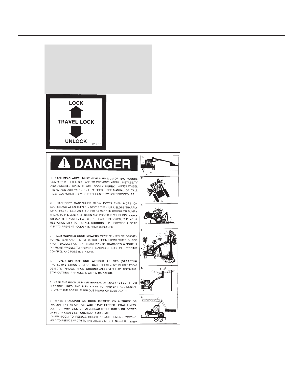
Each Rear Wheel must have a minimum of 1500 pound contact with
the surface to prevent lateral instability and possible tip-over which
could result in serious bodily injury or even death. Widen the wheel
tread and add weights if needed. Refer to the mounting instructions
or call Customer Service if you need assistance with Couterweight
Procedure. (SBM-11)
(SBM-7)
DANGER!
DANGER!
Always disconnect the wire leads from the mower pump solenoid
before performing service on the Tractor or Mower. Use caution when
working on the Tractor or Mower. Tractor engine must be stopped
before working on Mower or Tractor. The Mower Blades could
inadvertently be turned on without warning and cause immediate
dismemberment, injury or death. (SBM-12a)
The flail cutter shaft is designed for standard rotation (same
rotation as the tractor wheels during forward travel). Never operate the
cutter shaft in the reverse rotation. Operating this mower in reverse
rotation may cause objects to be thrown out the front of the mower
head.
Safety Section 1-10
Page 17

SAFETY
WARNING!
Engine Exhaust, some of its constituents, and certain components contain or emit
chemicals known to the state of California to cause cancer and birth or other reproductive
harm.
WARNING!
Battery posts, terminals and related accessories contain lead and lead compounds,
chemicals known to the state of California to cause cancer and birth or other reproductive
harm. Wash hands after handling!
Tiger mowers use balanced and matched system components for blade carriers, blades,
cutter-shafts, knives, knife hangers, rollers, drive-train components and bearings. These parts are
made and tested to Tiger specifications. Non-genuine “will fit” parts do not consistently meet these
specifications. The use of “will fit” parts may reduce mower performance, void mower warranties
and present a safety hazard. Use genuine Tiger mower p arts for economy and safety.
SEE YOUR DEALER
In addition to the design and configuration of this Implement, including Safety Signs and Safety
Equipment, hazard control and accident prevention are dependent upon the awareness,
concern, prudence, and proper training of personnel involved in the operation, transport,
maintenance, and storage of the machine. Refer also to Safety Messages and operation
instruction in each of the appropriate sections of the Tractor and Equipment Manuals. Pay
close attention to the Safety Signs affixed to the Tractor and Equipment. (SG-18)
Safety Section 1-11
Page 18

SAFETY
P ART NO.
LOCA TION
002369
HYDRAULIC T ANK
Safety Section 1-12
00725746
INSIDE OF CAB
00769737
MOWER DECK
Page 19

SAFETY
P ART NO.
LOCA TION
00758194
MOWER DECK
02962764
MAIN BOOM, SECONDARY BOOM, MAIN FRAME
02962765
MAIN FRAME
02965262
HYDRAULIC T ANK
Safety Section 1-13
Page 20

SAFETY
P ART NO.
LOCA TION
02967668
MOWER DECK
02971123
HYDRAULIC T ANK
03200285
OUTSIDE OF CAB
22645
INSIDE OF CAB
22839
MOWER DECK
Safety Section 1-14
Page 21

SAFETY
P ART NO.
LOCA TION
22840
INSIDE OF CAB
24028
MOWER DECK
25387
INSIDE OF CAB
Safety Section 1-15
10” x 5.5” 31522
MOWER DECK, MAIN BOOM
18.25” x 10” 31523
HYDRAULIC T ANK
13.5” x 7” 31513
Page 22
SAFETY
P ART NO.
LOCA TION
27001
INSIDE OF CAB
31935
INSIDE OF CAB
Safety Section 1-16
32707
HYDRAULIC T ANK
42350
MOWER DECK
Page 23

SAFETY
P ART NO.
LOCA TION
32708
HYDRAULIC T ANK
32709
INSIDE OF CAB
Safety Section 1-17
33224
MOWER DECK
33438
MAIN BOOM
Page 24
SAFETY
P ART NO.
LOCA TION
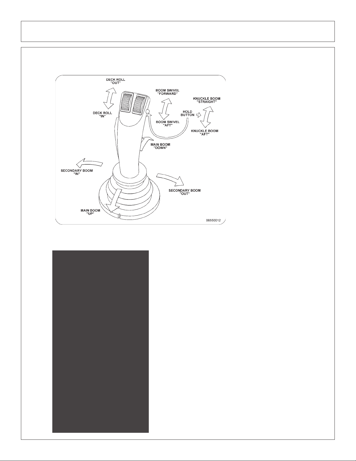
06550012
INSIDE OF CAB
Safety Section 1-18
33743
INSIDE OF CAB
Page 25

SAFETY
P ART NO.
LOCA TION
RED 42399
REFLECTIVE T APE
MOWER DECK
AMBER 4240006
REFLECTIVE T APE
MOWER DECK
6T3217
MOWER DECK
6T3219
INSIDE OF CAB
Safety Section 1-19
6T3220
FRONT PUMP MOUNT
Page 26

SAFETY
P ART NO.
LOCA TION
6T3221
INSIDE OF CAB
6T3222
INSIDE OF CAB
Safety Section 1-20
6T3224
MOWER DECK
6T3225
INSIDE OF CAB
Page 27

SAFETY
P ART NO.
LOCA TION
6T3230
INSIDE OF CAB
6T3231
INSIDE OF CAB
6T3233
HYDRAULIC T ANK
6T3234
INSIDE OF CAB
Safety Section 1-21
6T3236
MOWER DECK
Page 28

SAFETY
P ART NO.
LOCA TION
6T3237
INSIDE OF CAB
06550008
INSIDE OF CAB
6T3243
INSIDE OF CAB
6T3249A
MOWER DECK
6T3261
MOWER DECK
Safety Section 1-22
Page 29

SAFETY
TB1011
MOWER DECK
Safety Section 1-23
34852
HYDRAULIC TANK
Page 30
SAFETY
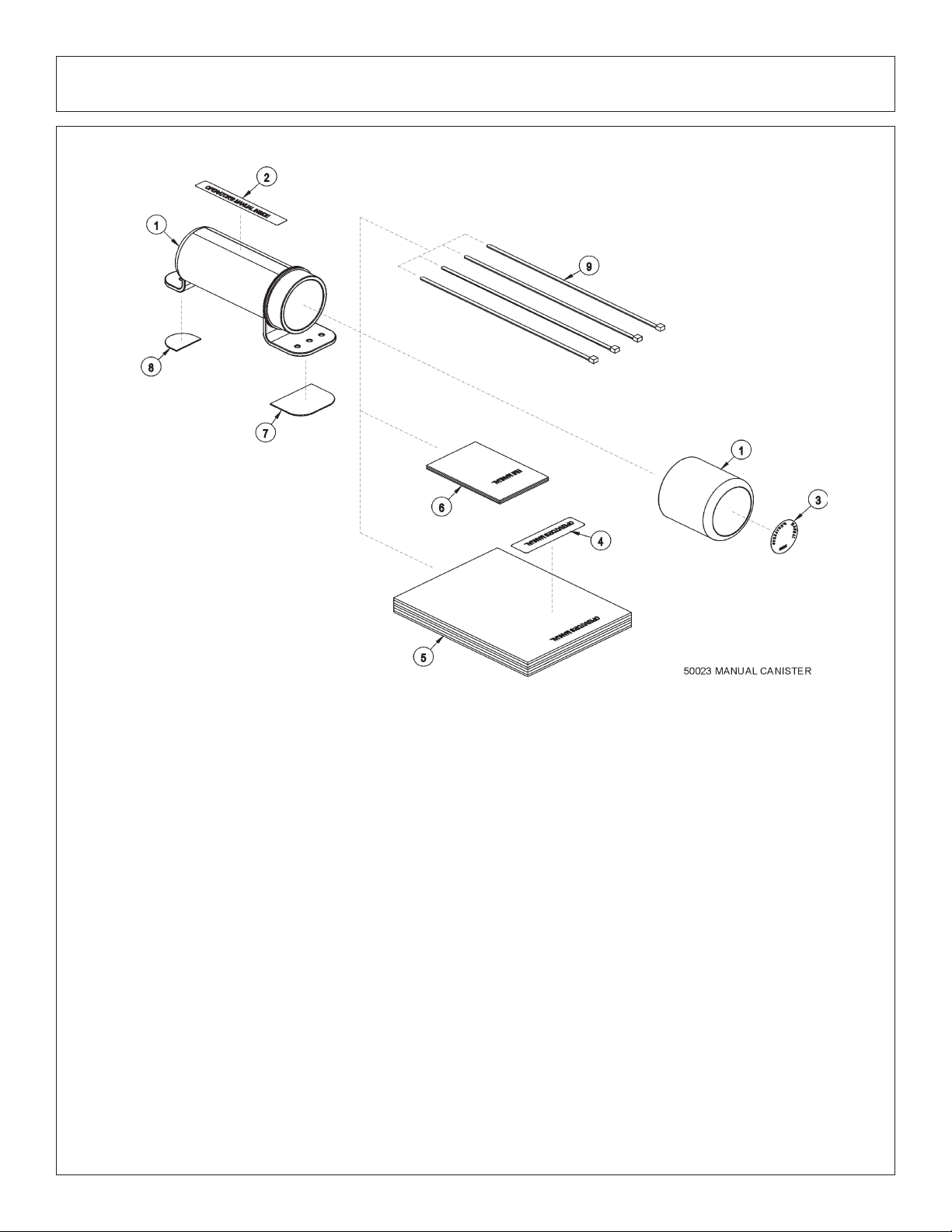
ITEM PART NO. QTY. DESCRIPTION
50023 AVAIL MANUAL CANISTER COMPLETE
1 00776031 1 ROUND MANUAL CANISTER
33997 1 DECAL, SHEET, MANUAL CANISTER
2 * DECAL
3 * DECAL
4 * DECAL
5 * AVAIL SPECIFIC PRODUCT MANUAL
6 33753 1 E M I SAFETY MANUAL
7 34296 1 FRONT ADHESIVE PAD
8 34297 1 REAR ADHESIVE PAD
9 6T1823 4 ZIP TIE 14” LONG
NOTE:
The manual canister can be bolted, zip tied or adhered to a variety of
surfaces. Locate a protected area within the view of the operator. Then
select an installation method and attach the canister . CAUTION - AVOID
DRILLING HOLES INTO UNKNOWN AREAS, wires and other parts may
be located behind these areas. When adhering the canister to a surface,
thoroughly clean that surface before installing the canister .
Safety Section 1-24
Page 31

SAFETY
FEDERAL LAWS AND REGULATIONS
This section is intended to explain in broad terms the concept and effect of federal laws and regulations
concerning employer and employee equipment operators. This section is not intended as a legal
interpretation of the law and should not be considered as such.
Employer-Employee Operator Regulations
U.S. Public Law 91-596 (The Williams-Steiger Occupational and Health Act of 1970) OSHA
This Act Seeks:
“...to assure so far as possible every working man and woman in the nation safe and
healthful working conditions and to preserve our human resources...”
DUTIES
Sec. 5 (a) Each employer(1) shall furnish to each of his employees employment and a place of employment which
are free from recognized hazards that are causing or are likely to cause death or serious
physical harm to his employees;
(2) shall comply with occupational safety and health standards promulgated under this
Act.
(b) Each employee shall comply with occupational safety and health standards and all
rules, regulations and orders issued pursuant to this Act which are applicable to his
own actions and conduct.
OSHA Regulations
OSHA regulations state in part: “At the time of initial assignment and at least annually
thereafter , the employer shall instruct every employee in the safe operation and servicing
of all equipment with which the employee is, or will be involved.”
Employer Responsibilities:
T o ensure employee safety during Tractor and Implement operation, it is the employer’s responsibility
to:
1. Train the employee in the proper and safe operation of the T ractor and Implement.
2. Require that the employee read and fully understand the Tractor and Implement Operator’s manual.
3. Permit only qualified and properly trained employees to operate the Tractor and Implement.
4. Maintain the Tractor and Implement in a safe operational condition and maintain all shields and
guards on the equipment.
5. Ensure the Tractor is equipped with a functional ROPS and seat belt and require that the employee
operator securely fasten the safety belt and operate with the ROPS in the raised position at all
times.
6. Forbid the employee operator to carry additional riders on the Tractor or Implement.
7. Provide the required tools to maintain the T ractor and Implement in a good safe working condition
and provide the necessary support devices to secure the equipment safely while performing repairs
and service.
Child Labor Under 16 Years of Age
Some regulations specify that no one under the age of 16 may operate power machinery. It is your
responsibility to know what these regulations are in your own area or situation. (Refer to U.S. Dept. of
Labor, Employment Standard Administration, W age & Home Division, Child Labor Bulletin #102.)
Safety Section 1-25
Page 32

SAFETY
Safety Section 1-26
Page 33

JD6X20 - BENGAL BRUTE
ASSEMBLY SECTION
Assembly Section 2-1
Page 34

ASSEMBLY
Before attempting to mount your Tiger mower, it is important
to read an understand all of the Safety Messages in the Safety
section of this manual.
Check complete shipment list against the packing list to make sure there are no
shortages. Make certain the tractor model is the appropriate one for the mower received!
Always use a floor jack, hoist or fork lift to lift and raise heavy parts.
Read and understand the entire assembly section instructions before attempting to mount
your Tiger mower. Refer to the parts section of this manual for detailed illustrations to locate all
parts.
(ASM-C-0001)
TRACTOR PREPARATION
A. Remove right and left hand steps.
B. Disconnect battery cables from both batteries.
C. Remove engine side panels, or raise hood to access front pulley.
D. Remove plugs from tractor casting where main frame and pump mount will be attached.
E. Remove any front weights and weight supports .
F. Raise the tractor onto jack-stands and remove the right and left rear wheels.
(ASM-JD-0001)
CRANKSHAFT ADAPTER
If necessary remove the four capscrews from the crankshaft pulley. Then install the crankshaft adapter to the pulley with capscrews and lockwashers as shown in the parts section.
(ASM-JD-0051)
Assembly Section 2-2
Page 35

ASSEMBLY
FRONT CRANKSHAFT PULLEY
Tiger has found that the front crankshaft pulley used by JD will not allow for the installation of a
front drive system. You will need to order a different pulley, washer and bolt from John Deere to allow
for a front drive to be installed on your tractor.
Inspect the front pulley on your tractor to verify you have the correct pulley needed to mount
the spacer plate. If your pulley has the (4) four holes needed to mount the spacer, your pulley is
the correct one needed. If your pulley does not have the (4) four holes in the pulley, you will need
to order the correct pulley, washer and bolt from John Deere.
PARTS REQUIRED TO PURCHASE FROM JOHN DEERE:
Pulley from JD - R516320
Washer from JD - R517237
Bolt from JD - R516648
Torque on the pulley bolt with locktite is 369 lb-ft.
Solution:
1. Clean nose of crankshaft using TY16285 clean and cure primer.
2. Apply a light 2-3mm bead of TY15969 retaining compound around the leading edge of the
crankshaft nose.
3. Dip damper mounting capscrew in clean SAE30 engine oil (Always use a new capscrew).
4. Position damper/pulley on the crankshaft and thread capscrew up tight (do not rely on the
capscrew to pull the pulley straight onto the taper).
5. Tighten capscrew to specification 500Nm (369lb-ft) (the engine will most likely have to be
pinned).
6. Measure run-out on the pulley, spec is 0.003” or less.
(ASM-JD-0080)
Assembly Section 2-3
Page 36

ASSEMBLY
DRIVESHAFT & FRONT PUMP MOUNTING
Install spacer plate on tractor engine using bolts and lockwashers as shown in parts section.
Grease sleeve section of the driveshaft and install from the side of the engine compartment.
Once you have the sleeve section in place, bolt to spacer plate using bolts and lockwashers as
shown in parts section. Install shaft end of driveshaf t throu gh opening and into driveshaf t sle eve.
Shaft and sleeve yokes should be aligned, if shaft does not insert easily in sleeve, turn shaft
180°, and then install. Shaft end must be installed in correct orientation, failure to do so
may result in damage to tractor and/or driveshaft. After installation of shaft end, install pump
mount. Next, install pump. After pump is secured, inst all driveshaft in to pump shaft. The end of
driveshaft should be no more than 1/2” away from contact with pump housing. Tighten crimping
bolt on driveshaft. Lube driveshaft & check all hoses, flanges, the pump, pump mount, driveshaft
and mounting plate to ensure all fasteners are tightened before operation.
CAUTION: DO NOT START THE TRA CTOR UNTIL ALL HOSES ARE ATTACHED, TANK
IS FILLED WITH PROPER OIL AND BALL VALVES ARE OPEN! STARTING AT THIS TIME
WILL CAUSE SERIOUS DAMAGE TO THE PUMP.
(ASM-JD-0216)
ADJUSTING REAR WHEELS
Raise rear of tractor onto jack-stands. Follow the instructions in the tractor owners
manual for adjusting tires and rims. The back wheels MUST be adjusted to the widest
setting. NOTE: This may require switching the wheels to opposite sides of tractor. Also take
note of any width restrictions when transporting by trailer. (For ease of installation, it is best to
leave the rear wheels removed during installation of the mower.)
(ASM-B-0001)
WEATHER-PACK/METRI-PACK ASSEMBLY
These instructions apply to both Weather-Pack and Metri-pack connectors.
NOTE: Use the specific tool for the type of connector you are assembling.
(ASM-C-0009)
Assembly Section 2-4
Page 37

ASSEMBLY
POLYCARBONATE SAFETY WINDOW
NOTE: Installing a boom mower requires that all of the right side windows be replaced, or
protected with a polycarbonate window. This should be done before mounting the main frame.
1. Disconnect gas shock at door . Remove the right side cab door/window glass from tractor cab
by removing hinge pins. Also, remove rear right side window.
2. Remove the existing hardware and discard factory glass door and window.
3. Place small bead of adhesive seal in the bottom of the trim lock bubble seal.
4. Install trim lock bubble seal on polycarbonate starting at the center bottom horizontal portion.
5. Install existing hardware removed from glass door and window on the polycarbonate.
6. Install the polycarbonate assembly in the cab with existing and supplied hardware.
7. Place the retaining brackets on the upper front and lower front (if applicable) of the cab door/
window with the 8mm capscrews.
8. Place the last bracket at the bottom of the door by the fender as shown in the illustration
below. Hold the bracket in place and mark the door jam.
9. Drill a 21/64” hole in the door jam for the 5/16” capscrew and moun the bracket.
10. Install the right rear poly window into place where the factory window was removed (if applicable).
(ASM-JD-0052)
Assembly Section 2-5
Page 38

ASSEMBLY
MAIN FRAME INSTALLATION
With an overhead hoist and / or jack-stands, raise one side of the frame up to the correctly
matching mounting holes. Install capscrews and all other hardware as shown in main frame
parts section to secure the sides of the main frame to the tractor casting, DO NOT tighten at this
time. Remove the capscrews one at a time and apply a thread locking agent. Reinsert the
capscrews and tighten / torque to values noted in the torque chart located in the maintenance
section of this manual.
(ASM-C-0003)
JOYSTICK CONTROL VALVE MOUNTING (CAB)
Align the mounting bracket to the existing holes on top of the tractor remote valve at the rear
of the tractor. Secure the bracket to the tractor with hardware shown in the parts section of the
manual. Then place and secure the lift valve on top of the mounting bracke t. In stall the electrial
control cables and route the hydraulic lines from the lift valve to the hydraulic cylinders as noted
on the lift valve page of the part section.
(ASM-JD-0205)
Assembly Section 2-6
Page 39

ASSEMBLY
CABLE VALVE MOUNTING PLATE (CAB)
Align the mounting bracket to the existing holes on top of the tractor remote valve at the rear
of the tractor. Secure the bracket to the tractor with hardware shown in the parts section of the
manual. Attach the valve mounting plate to the valve mounting bracket on the rear to the tractor
as shown below. Then place and secure the lift valve on top of the mounting plate. Install the
control cables and route the hydraulic lines from the lift valve to the hydraulic cylinders as noted
on the lift valve page of the parts section.
(ASM-JD-0206)
Assembly Section 2-7
Page 40

ASSEMBLY
CABLE CONTROL LEVER STAND
On the corner cab post, mark a point at 1-3/8” from the windshield and 22-1/2” from the floor;
then cut a 3/4” diameter hole through the outer plastic shell. This will expose a threaded steel
boss to attach the control box support bracket.
The rear corner of the cable control stand is placed
approximately 6-1/4” from the edge of the mat. The front
edge of the stand is up against the corner cab post and the
door sill lip of the mat. Before you mark or drill any holes,
check for support plates or wires under the mat & the cab
floor. NOTE: Cutting into plates or wires makes more work
for everyone and could be dangerous. When you know
where the wires/plates lie, mark one of the mounting holes.
Drill a 3/8” hole through the mat and through the floor of
the cab. Next, lift the mat up and mark the other two holes
on the cab floor . Drill the holes through the floor. Mark the
mat and drill the other two 3/8” holes. Use a 1” hole saw
and cut a 1” hole through the mat over each 3/8” hole.
Secure the stand to the floor with the spacers, capscrews and nylock nuts provided.
Cut a 1-3/4” hole in the floor to route the cables and wires through. It needs to have a 1/4”
clearance for the trim lock. Before you mark or drill any holes, check for support plates or wires
under the cab floor.
NOTE: Cutting into plates or wires makes more work for
everyone and could be dangerous. Look under the floor
for cables and plates that you need to avoid. The hole
should be approximately 4-1/2” from the door sill and
4-3/4” from the lip of the mat under the console. Install the
trim lock around the metal edges of the hole, then route
the control cables and wires through the hole.
Next, wrap the cables with the 6” split hose at the point
they pass through the hole, and secure the zip-ties. Apply
RTV sealer in and around individual cables and split hose, inside and outside of the cab for a
water tight seal. Install upper support bracket from cab post to the control lever stand.
(ASM-JD CBL MNT-0002)
Assembly Section 2-8
Page 41

ASSEMBLY
WIRE ACCESS FOR SWITCH BOX (CABLE)
Refer to the parts section for wiring diagrams. Remove right side cowl panel, tach
panel, and hour meter panel for access to the wires.
Route the red wire from the switch box to the bare electrical plug in the fuse box, or
other un-used “keyed” hot wire. NOTE: +12 VOLTS ELECTRICAL POWER MUST BE
TAKEN FROM A SOURCE LOCATION WHERE IT IS LIVE ONLY WHEN THE IGNITION
SWITCH IS IN THE “ON” POSITION.
Drill a ½” hole in the 9” X 5” right side panel to route the green & blue safety switch
wires.
The switch box is to be secured to the operators side of the control handles, or valve
stand.
The green & blue wires will connect to the neutral safety switch blue wires, located on the
back of the ignition switch, under the cowl panel.
(ASM-JD-0218)
CABLE SWITCH BOX WIRING
Refer to the parts section for wiring diagram to hook up the switch box. Cover all the
wires from the switch box with plastic wire wrap provided. Route the wires from the switch
box to the front console panel as shown on previous page. Remove the console panel
under the steering wheel to access tractor wires. Locate the brown colored wire. Using
a test light or meter to verify this wire is the neutral safety wire. Cut the bro wn wire and
connect the green wires from the switch box as shown in the wiring diagram.
To run the white wire to the solenoid valve, you will need to drill a hole in the front edge
of the cab floor on the right side of the front console. Insert a rubber grommet into the hole
to protect the wire, and route the wire out of the cab.
The red wire is to be hooked to the tractor ignition switch or an available slot in the fuse
box. NOTE: Be certain that the power taken for the switch box is “HOT” only when
the tractor ignition is “ON”. Also double check that the line is fused.
The travel lock red wire from the switch box should also run with the white wire through the
rubber grommet and be covered with wire wrap. This wire will be connected to the electronic
travel lock located on the main boom cylinder. The wires from the switch box are longer than
needed and should carefully cut and spliced as required. Zip ties should be used to secure the
wires to the tractor framework and boom hoses to eliminate vibation and rubbing.
(ASM-JD-0204)
Assembly Section 2-9
Page 42

ASSEMBLY
*NOTE ON HUSCO CONTROL VALVES*
Manual, cable controlled (Husco control valve) boom mowers require check valves with integral restricting orifice (#06502036) installed in the control valve work ports that are connected to
the gland ends of the main and secondary boom cylinders. This check valve allows oil to free
flow into the gland end of the main and secondary boom cylinders, but restricts flow out of the
cylinder, thereby providing proper boom control. This check valve, #06502036(Vendor #1968R.063) is similar in appearance to hose adapter #33271 and Adapter #34396, with.06 orifice.
These components can be identified as follows, and are to be installed per parts section for the
lift valve.
(ASM-HUSCO-0001)
Assembly Section 2-10
Page 43

ASSEMBLY
JOYSTICK SWITCH BOX WIRING
Refer to the parts section for wiring diagram to hook up the switch box. Cove r the four wires
(1-white / 2-green / 1-red) from the on / off terminal of the switch box with plastic wire wrap
provided. Run these wires through the drilled hole in the right side panel of the steering column
on previous page.
With the panel under the steering wheel removed to access the wires, locate the brown wire.
Using a test light or meter to verify this wire is the neutral safety wire. Cut the brown wire and
connect the green wires from the switch box as shown in the wiring diagram.
To run the white wire to the solenoid valve, you will need to drill a hole in the front edge of the
cab behind the front council. Insert a rubber grommet into the hole to protect the wire, and route
the wire out of the cab to the solenoid valve.
The red wire from the on / off termina l is to be hooked to the tractor ignition switch o r an available
slot in the fuse box. NOTE: +12 VOLTS ELECTRICAL POWER MUST BE TAKEN FROM A
SOURCE LOCATION WHERE IT IS LIVE ONLY WHEN THE IGNITION SWITCH IS IN THE
“ON” POSITION. THIS WIRE MUST BE FUSED AT THE SOURCE LOCATION
The travel lock red wire from the switch box should also be covered with wire wrap and
should run with the white wire through the grommet. This wire will be connected to the electronic
travel lock located on the main boom cylinder. The wires from the switch box are longer than
needed and should be carefully cut and spliced as required. Zip ties should be used to secure
the wires to the tractor framework and boom hoses to eliminate vibation and rubbing.
The black ground wire from the switch box can be attached to the switch box mounting
bracket.
A 2-1/8” hole must be drilled in the floor of the cab on the right side of the steering wheel. The
center of the hole is located 12” from the front window and 4-1/2” from the right cab door. Shown
on the next page.
Wrap the valve cables in hose wrap and route the cables through the hole in the floor of the
cab. The hose wrap will stick out above and below the hole in the cab floor. Use zip ties to
secure the hose wrap to the cables. Seal the edge of the hole with silicon sealant or strip caulk.
(ASM-JD-0219)
Assembly Section 2-11
Page 44

ASSEMBLY
JOYSTICK SWITCH BOX MOUNTING
Locate the 2 holes in the right front corner of the cab frame. These will be the mounting
holes for the 2 mounting bolts of the switch box bracket. See picture below. Mount the bracket
using the hardware supplied, as noted in the parts section.
(ASM-JD-0220)
Cut slot in right side panel of steering column to run wires from switch box. NOTE: When
cutting or drilling hole, be sure not to damage existing wires running behind panels.
Assembly Section 2-12
Page 45

ASSEMBLY
JOYSTICK CONTROL MOUNTING
The joystick control will require that the right armrest be modified and an additional
bracket attached that will accommodate the joystick. In doing this, the armrest must be
removed by sliding off the plastic cover and removing the capscrew from the lower right
side of the seat. After the capscrew is removed the armrest should be loose from the seat
and able to be removed at this point. Once the armrest is removed, then place the joystick
holder under the armrest, so that the indentation on the outside of the armrest is lined up
with the hole in the armrest bracket for the capscrew to pass through. Once the correct
placement is achieved, then mark on the armrest where the hole passes through the
armrest bracket. At this point a 1/2” hole must be drill through the armrest so that the
bracket can be secured to the armrest. After the hole is drilled, then on the inside of the
armrest the 1/2” hole must be cut to a larger diameter up to the metal plate in the armrest
so that a spacer and hex nut can be fastened to the capscrew that secures the armrest
bracket. Install the armrest bracket on the armrest with the hardware as shown in the parts
section. Once the bracket is installed on the armrest then reattach the armrest back onto
the seat using the existing hardware previously removed. Then install the joystick in the
bracket with the machine screws as shown in the parts section.
(ASM-JD-0082)
PRESSURE LINE INSTALLATION (2004 UPDATE)
The hydraulic pressure line will be plumbed into the rear of the tractor remote valve end cap.
Locate the pressure port on the end cap and remove the plug (refer to the illustration below and
the Parts Section pages for position of the pressure port). After the plug is removed then install
22mm adapter. Next connect a 1/2” hose from the tractor remote valve to the Tiger valve.
(ASM-JD-0212)
Assembly Section 2-13
Page 46

ASSEMBLY
RETURN LINE INSTALLATION (2004 UPDATE)
The return line will be plumed in next to the pressure line in the tractor remote valve end cap.
Locate the return port and remove the plug (refer to the illustration below and the Parts Section
for the position of the return port). After the plug is removed then install 22mm adapter or elbow.
Next connect a 1/2” hose from the tractor remote valve to the Tiger valve.
(ASM-JD-0213)
LOAD SENSE LINE INSTALLATION - JOYSTICK (2004 UPDATE)
The load sense line will be plumbed into the side of the tractor remote valve (shown in the
picture on the last page). Install the end cap onto the re mote valve as shown. This end cap is a
Tiger custom part to obtain proper operation of the lift valve. Locate the plug on the end cap for
the load sense, and remove the plug. Install a 1/4” hose from the end cap to the Tiger valve.
Refer to the Parts Section pages for an exploded diagram of the tractor remote valve hookup.
(ASM-JD-0214)
Assembly Section 2-14
Page 47

ASSEMBLY
LOAD SENSE LINE INSTALLATION - MANUAL (2004 UPDATE)
To install the load sense line from a Husco valve to the tractor remote valve, first locate
the load sense port located on the bottom of the end cap. Remove the plug and install
14mm elbow, then attach the 1/4” hose to the end cap and to the top front port on the
Husco valve.
For more information refer to the Parts Section pages for a complete diagram of the tractor
valve hookup.
(ASM-JD-0215)
2004 UPDATES APPLY TO THESE MODEL’S
JD6000 SERIES SERIAL #’S WITH THIS CHANGE: 391333, 391640, 392239, 39589 1, 39 619 0, 39 7161,
396515, 396572, 396560, 396777, 396754, 396764, 396981, 397327, 396983, 396987, 397165, 397159,
397211, 397773, 397450, 397354, 397341, 397498, 397527, 397520, 397360, 3974 75 , 3 975 38, 39 7569,
397554, 397545, 397585, 397506, 397570, 397587, 397575, AND MODEL #’S STARTING WITH
#398797.
ACCUMULATOR INSTALLATION
Install the accumulator bracket on tab with holes provided on the right main frame or lif t valve
mount, if applicable, with the capscrews and lockwashers as shown in the Parts Section. Install
the accumulator in the bracket and secure with the hardware shown. Inst all fittings and hoses to
the cylinder and control valve as shown in the Parts Section. Use teflon tape on all pipe
fittings (except O-rings).
(ASM-C-0012)
Assembly Section 2-15
Page 48

ASSEMBLY
SELECTOR VALVE INSTALLATION
NOTE: Refer to the parts section and illustration below for hardware and position.
The selector valve is attached to the boom rest. The 1/4” hoses from the swivel section of the
lift valve are plumbed to the “A” and “B” ports on the selector valve. A run tee is added to the
return section of the lift valve. Attach the 1/2” hose from the “T” port of the selector valve to the
run tee on the lift valve. 1/4” hoses are attached to the “A1”, ”A2”, “B1” & “B2” ports on the
selector valve to the knuckle cylinder and swivel cylider.
(ASM-SLCTR VLV INSTLN-0001)
FILLING HYDRAULIC RESERVOIR
Refer to the maintenance section for filling specifications and hydraulic oil requirements.
NOTE: Starting or running your Tiger mower before filling reservoir will cause
serious damage to hydraulic pump.
(ASM-C-0004hydro resrv)
SIDE HYDRAULIC TANK INSTALLATION
Install all fittings and tubes into tank and tank filter as shown in the Parts Section illustration.
Insert tank sight glass into front side of tank.
Place the tank in the mounting bracket on the main frame as shown in the Parts Section.
Secure the tank with the tank channel mount by placing the channel mount on top of the tank and
the washers over the holes. Thread the tie bolts through the washers and holes to the threaded
holes on the main frame. Tighten the tank channel mount by using the hex heads on the end of
the tie bolts.
Install the filter gauge into the filter housing so that it points to the rear of the tractor and is
clearly visible to the operator. The tank breather cap is ready for use as the tank is filled. Some
of the for-metioned items may be already installed.
(ASM-MOTOR HYDRO-0001)
GENERAL HOSE INSTALLATION
Refer to the parts section for detailed information about hoses and fittings for this application.
(ASM-C-0011)
Assembly Section 2-16
Page 49
ASSEMBLY
TEMPERATURE GAUGE MOUNTING (OPTIONAL)
Mount the temperature gauge where it is clearly visible to the operator. Attach the green (-)
wire from the negative post on the gauge to a grounded bolt on the tractor frame. Remove paint
if needed to make a good ground. Remove the pipe plug from the side of the hydraulic reservoir
and install the temperature sensor using thread sealing tape. Run the white wire from the (s)
sensor post of the gauge to the temperature sensor on the hydraulic reservoir tank.
(ASM-C-0051)
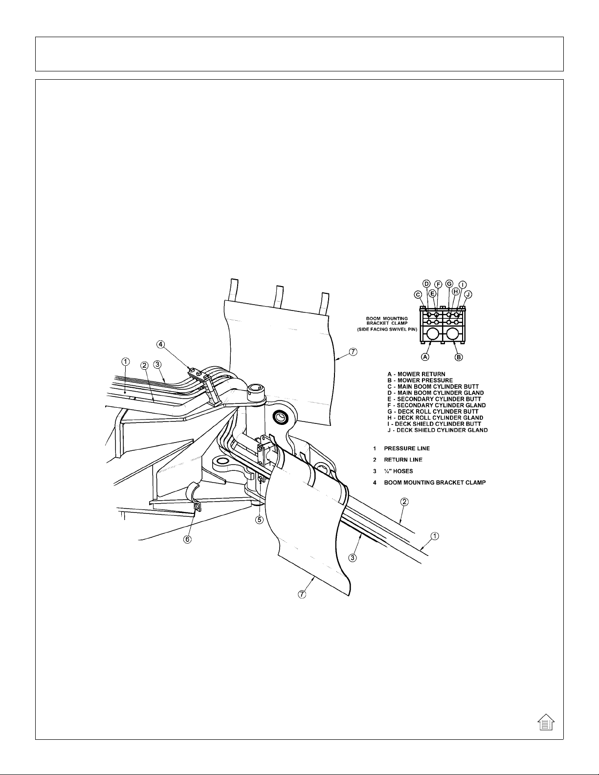
BENGAL BRUTE HOSE ROUTING
WARNING NOTE: The sudden release of hydraulic pressure could cause the sudden
movement of very heavy parts. Anyone in the way of these parts could be severely hurt or killed.
DO NOT ALLOW these hydraulic hoses to BREAK or BURST in order to prevent hydraulic failure
Make sure the hoses do not pinch or stretch as boom moves. Measure TWICE, check TWICE
then proceed with caution.
Route the hoses through the space between the swivel and the boom mounting bracket.
Connect the hoses to the preformed tubes and move the boom arm to a few feet from full
forward. Assemble the swivel clamp and place the return hose for the motor on top and the
pressure line on the bottom. Place the ¼” hoses in the “C” clamp and add it to the bottom screw
of the swivel clamp. Next, make sure there is enough slack for all hoses to pivot at the joint
where the main boom arm bends in the swivel, as shown in the next image, and tighten the
hoses in the clamp.
(ASM-BRUTE HOSE ROUTING-0001A)
Assembly Section 2-17
Page 50

ASSEMBLY
BENGAL BRUTE HOSE ROUTING (Continued)
Arrange the hoses in the clamp that attaches to the boom mou nting bracket as shown abo ve,
with the 1” motor hoses closest to the bracket and the return hose closest to the boom arm. Pull
the hoses snug from the swivel to the mounting bracket clamp s, when main boom is still forward,
and tighten the hoses in the clamp.
Make sure the 1” motor hoses do not kink as the boom arm is moved into the stowing
position. If this happens the motor hoses will have to be shortened, because there is too much
hose between clamps.
(ASM-BRUTE HOSE ROUTING-0001B)
Assembly Section 2-18
Page 51

ASSEMBLY
(ASM-C-0094)
Assembly Section 2-19
Page 52

ASSEMBLY
GREASELESS BEARING INSTALLATION
It is recomended that grease is to be applied to the bore to aide in insertion of the greaseless
bearing.
(ASM-GRSLSS BRNG-0009)
Assembly Section 2-20
Page 53
ASSEMBLY
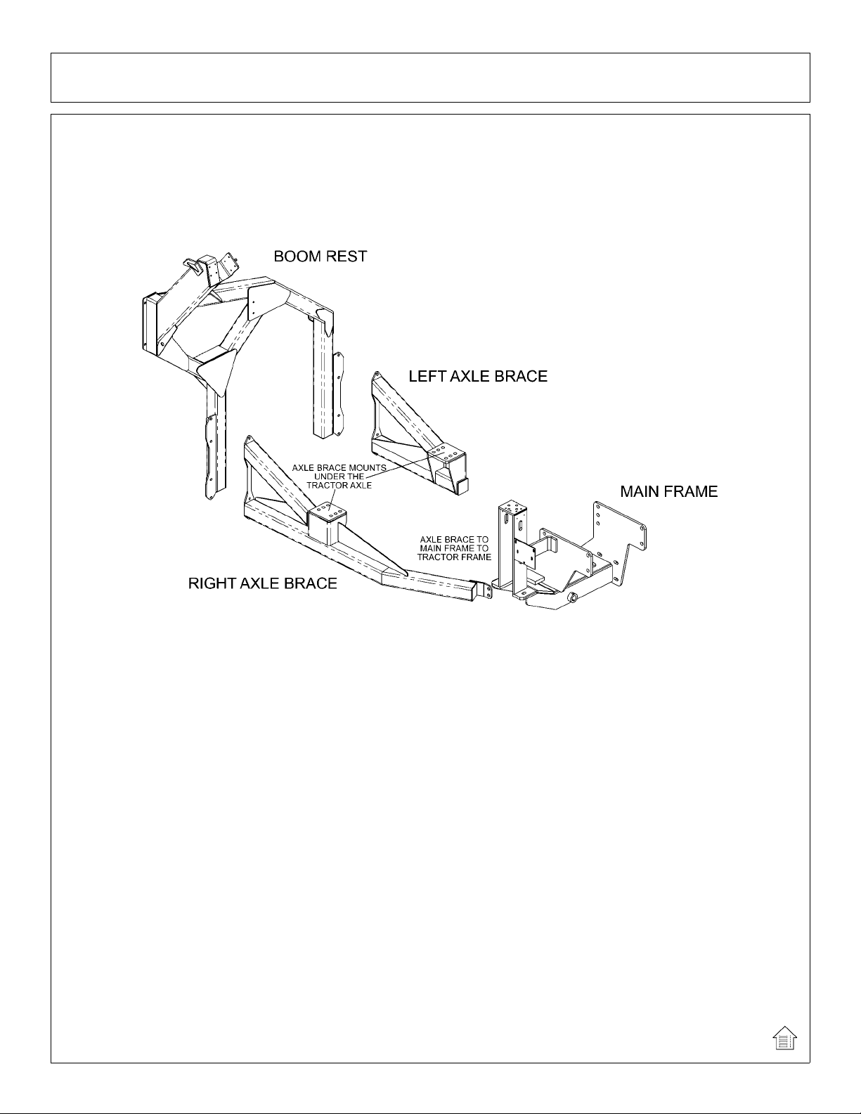
RS AXLE BRACE MOUNTING
The rear stow axle braces are to be mounted under the rear axle of the tractor. The other
end of the axle brace mounts on the outside of the lower rear corners of the main frame. After
attaching the boom rest, it should fit tightly and level under the tractor. Attach the axle brace(s) to
the main frame with hardware shown in the Parts Section and tighten. Attach the axle braces to
the rear axle using the mounting hardware shown in the parts section, but DO NOT tighten.
RS BOOM REST MOUNTING
Carefully raise the rear stow boom rest and align the holes with those of the axle brace. Now
install all attaching hardware as shown in the parts section loosely, to allow for the alignment with
the left and right axle brace. Tighten / torque all hardware on the brace and the boom rest.
Finally, add the rest strips to the boom rest as shown in the Parts Section.
(ASM-JDBOOM-0001)
BOOM MOUNTING BRACKET
Using a floor jack and / or a hoist, raise the boom mounting bracket up to level and slide the
bracket into position onto main frame as shown in parts section.
Install pin through main frame and bracket. Secure with cap-screw, lock-washer and hex nut
through boss on main frame as shown.
Secure mounting bracket to main frame with the cap-screws, lock-washers, flat-washers, cut
flat-washers and hex nuts provided. Secure using the two slotted holes on the bra cket and main
frame.
(ASM-C-0014)
Assembly Section 2-21
Page 54

ASSEMBLY
SWIVEL BRACKET MOUNTING
Install the boom swivel bracket onto the boom mounting bracket with the swivel pin. Secure
the pin in place using the capscrews, etc. through the hole in the boss and pin. NOTE: The head
of the capscrew must be toward the front of the tractor.
Install all new swivels and fittings on the swing cylinder with swivel openings facing each
other. Fittings will vary in type and direction depending on your application, refer to your parts
section for more details.
Install bearings in the main frame anchor for the swing cylinder. This may already be done
for you.
Install the swing cylinder between the boom mounting bracket cylinder anchor and the boom
swivel with the pins. Insert roll pins through the top and the bottom hole in the pins.
Now the hoses can be attached from the control valve to the swing cylinder.
(ASM-C-0015)
PREFORMED TUBE INSTALLATION
Lay booms on floor so the side with the nuts welded on is up. If mounting a ditcher head,
only the main boom tube installation is required. Locate all tube clamps and install them loosely
in the welded nuts on the left side of the booms.
Arrange the tubes and hoses as outlined in the parts section diagram. Install the smaller tube
closest to the boom arm, being careful not to pinch the tubes. Place the large tubes outside of
the small tubes. Snug all clamp bolts, but do not tighten. Check all tubes for correct alignment
and that none are pinched or bent. The clamp bolts can now be tightened.
(ASM-C-0016)
MAIN BOOM INSTALLATION
Install the boom swivel into the main frame as shown in the parts section using a hoist. Line up holes
in swivel and main frame for large swivel pin and insert pin. Secure with hardware as shown.
Attach the inner end of the main boom to the swivel bracket with the cylinder anchors positioned
upward, and at a right angle to the tractor. Secure it with the horizontal hinge pin. Secure the hinge pin in
the boss with capscrews, etc. (see Parts Section).
Attach the butt end of the main boom cylinder to the swivel with the cylinder pin and roll pins shown in
the Parts Section.
Install the travel lock on the rod end of the main boom cylinder. This should be facing the butt end of
the cylinder after installation.
Install the fittings and hoses to the main boom cylinder per Parts Section.
GREASE HINGE PIN ZERKS ON BOOM AFTER ASSEMBLY, ONCE UNDER LOAD WITH BOOM
ELEVATED AND AGAIN AT REST WITH BOOM SUPPORTED
(ASM-C-0013)
SWITCHING SIDE MOUNT TO BOOM ARM
If you are changing over from a side mounted mower you must first close the ball valves and
remove the motor hoses from the motor to the solenoid valve. Also remove and replace any
fittings that do not match the ones shown in the parts section diagram.
Next, disconnect all hoses from the control valve. Remove the pin that connects the lift
cylinder to the mast on the main frame. Remove the inner draft beam pin.
At this point the mower should be loose from the tractor.
Remove the two spool valve and mount the four spool valve for the boom according the
diagram in the parts section. Also refer to the parts section for the new hoses that will need to be
used.
(ASM-C-0020)
Assembly Section 2-22
Page 55

ASSEMBLY
DECK ATTACHMENT
The pivot assembly is used to attach the head to the secondary boom. Install the deck pivot
cylinder using the pins and hardware, which is illustrated in the common section.
Connect the fittings and hoses from the pivot cylinder to the small preformed tubes on the
boom arm. Connect the fittings and hoses from the motor to the large preformed tubes on the
boom arm. Connect all remaining hoses from the control valve to the cylinders and / or
preformed tubes on the boom arm. Refer to common section for diagrams.
(ASM-C-0018)
SOLENOID BRAKE VALVE
Install a solenoid valve mounting bracket with the supplied hardware. While installing fittings
to the brake valve, the electrical coil on the spool must be removed to make room. When
reinstalling the coil, it is important to use no more than 5 ft. lbs. (or 60 in. lbs.) torque. Over
torque to the coil will result in hydraulic failure of spool.
(ASM-C-0017)
HOSE COVERING
Secure hoses together with zip ties wherever loose. Wrap the hoses with the hose covers as
illustrated in the parts book. Where hoses may contact the frame or other edges, wrap with split
hose and secure with hose clamps or zip ties. On non cab units the pressure and return hoses
from the control valve will also need to be routed inside the protective clear hose wrap.
(ASM-C-0019)
INSTALLING O-RING FITTINGS
Installing straight, 45º and 90º O-rings requires that the O-ring and washer be up against the
swivel body . Insert the swivel and turn in until the swivel is pointed in the desired direction and Oring contact is made. Hold swivel in set direction with a wrench and turn the O-ring nut away
from the swivel body and carefully tighten.
(ASM-C-0056)
Assembly Section 2-23
Page 56

ASSEMBLY
WHEEL WEIGHT MOUNTING
For all tractors using a boom mower, a wheel weight will be required for the rear left side
wheel. It will be necessary to mount the weight in the wheel using the long capscrews,
lockwashers, flatwashers, spacers (if applicable), and hex nuts per the diagram in the parts
section.
Installation is most easily done with a fork lift, inserting a fork in the center slot of the wheel
weight. The head of the capscrews is to be toward the OUTSIDE of the weight, with flatwashers
on both the inside and outside of the assembly.
The left rear tire may also be filled with a mixture of water and calcium chloride at about five
pounds per gallon. Tire air pressure should be maintained according to the Maintenance
Section.
(ASM-C-0055)
EXTENDING ZERK ON FLAIL HEAD
Due to the belt shield covering the cutter shaft bearing on the flail head a hose, elbow, &
grease zerk have been added to the bearing. Remove the existing grease zerk from the bearing
and discard. Attach the elbow to the bearing. Next, the hose is attached to the elbow and routed
through the belt shield(shown below) and attached to the outside of the shield. The additional
zerk is connected to the end of the hose for easier bearing maintenance.
After assembling all components, double check the complete assembly from the main
frame to the cutter head. Check the diagrams in the parts sections for proper placement
and assembly of all components.
(ASM-FLAIL-0001)
Assembly Section 2-24
Page 57

ASSEMBLY
BOOM JOYSTICK CONTROL CALIBRATION
SUB-D
This Danfoss PVG32 control valve is now equipped with higher-resolution actuators on Main
Boom, Secondary Boom, Deck Roll, and Swivel functions. These actuators have “active fault
monitoring”. The Deck Shield section does not have “active fault monitoring”. The joystick is
unchanged and provides a ratio-metric voltage signal. The neutral signal voltage is half or 50%
of tractor supply voltage. A 25% signal voltage will shift the valve spool to full “A-Port”, and 75%
signal voltage will shift the spool to full “B-Port” in the Main, Secondary, and Swivel valve
sections. On the Deck Roll function a 34% signal voltage will shift the valve spool to full “A-Port”
and a 68% signal voltage will shift the spool to full “B-port”. If an actuator with active fault
monitoring receives a signal from the joystick that is less than 15% or greater than 85% of supply
voltage the actuator will “fault out” and shut down. Also if there is an internal failure in the
actuator or if the spool position is greater than that specified by the signal voltage from the
joystick, the actuator will “fault out” and shut down. An “active fault” condition causes the
actuator to drive the spool to neutral, shut down, and activate a “red” LED on the top of the
actuator. The active fault can be canceled by simply cycling the Master Switch “OFF” and then
“ON”, which resets the fault monitoring, and causes the LED on top of the actuator be “green”
again..
The joystick control is equipped with signal adaption potentiometers.
These provide the capability to individually adjust the oil flow to each boom function. It is
important that the boom functions do not travel too fast. Excessive boom speed can reduce the
stability of the unit and decrease operator control.
Note: Use a Phillips screw driver and be sure to adjust the screws carefully! DO NOT turn
the potentiometers beyond their stopping point, potentiometers are very delicate! Tu rning the “A”
or “B” port potentiometers clockwise increases the oil flow to increase the boom function speed,
and turning them counterclockwise decreases the oil flow to decrease the boom function speed.
See the graphic on the next few pages for help in adjusting.
Assembly Section 2-25
Page 58

ASSEMBLY
Run tractor at normal operating RPM to adjust the settings as follows.
Set the dead band compensation potentiometer first.
Set the dead band compensation potentiometer at 50%, or halfway between full clockwise and
full counter-clockwise.
Setting Signal Adaptation Potentiometers:
Disconnect the Deutsch connectors from the actuators of the valve. Use a Volt/Ohm meter to
measure signal voltage and adjust the signal adaptation potentiometers as needed. Pin #4 is
tractor supply voltage. Pin #1 is signal voltage from the joystick, and pin #3 is ground. First
measure supply voltage between pins 4 and 3 . Then measure signal volt age between pins 1 and
3 while indexing the joystick function fully in both the “A” and “B” port direction. Divide the signal
voltage by the supply voltage to get signal voltage as a % of supply voltage. This percentage
should not be less than 25% or greater than 75% for the Main Boom, Secondary Boom, or Swivel
function. This percentage should not be less than 30% or greater than 62% for the Deck Roll
function. Note these initial settings for the Deck Roll function should prevent the spool from
shifting into float. After making this first adjustment to deck roll if the spool still goes into float,
adjust the “B” port screw additionally counterclockwise.
Reconnect Deutsch connectors on control cables to actuators on Danfoss valve. Run tractor
until hydraulic system is at operating temperature. Now refine the adjustments of the signal
adaptation potentiometers for both “A” and “B” ports for all proportional functions to achieve the
following function times. Note: turning potentiometer clockwise increases the flow or the function
speed, and turning them counter-clockwise decreases the flow or the function speed. Note, if
during this procedure the trim potentiometer is set to full “counterclockwise” but the function is
still too fast, use the mechanical stops at the manual actuator end of the valve section to further
limit flow. Turn limit screw in or clockwise to limit flow. The upper limit screw limits flow to “Bport”, and the lower limit screw limits flow to “A-port”. However DO NOT adjust the limit screw on
“B-port” of deck roll function. Limiting “B-port” will prevent “float” function.
Assembly Section 2-26
Page 59

ASSEMBLY
MAIN BOOM: “A” Port, Boom UP: 7-9 Seconds
(Note: Extend secondary boom completely; roll deck to be level with ground, and lower main
boom until deck is on ground. Now index main boom “up” function and determine the time
required for main boom to rise completely.)
“B” Port, Boom Down: 6-8 Seconds
(Note: Extend secondary boom completely, roll deck to be level with ground, and raise the main
boom to “full up”. Then index the main boom “down” function to determine the amount of time
required for the deck to contact the ground. CAUTION: Stop the boom just as the deck contacts
the ground.)
SECONDARY
BOOM: “A” Port, Boom Out: 8-10 Seconds
(Position main boom full up, roll deck out until deck cylinder is fully retracted, and bring
secondary boom in completely . Then index the secondary boom “out” function and determine the
time required for boom to extend out completely.)
“B” Port, Boom In: 8-10 Seconds
(Position the main boom full up, roll deck out until deck cylinder is fully retracted, and extend
secondary boom completely. Then index the secondary boom “in” function and determine the
time required for boom to come in.)
DECK ROLL: “A” Port, Deck Out: 7-9 Seconds
(Raise main boom to vertical, extend secondary boom out slightly so th at de ck ca n be articulated
without contacting the main boom, and roll deck in until deck cylinder is completely extended.
Then index the deck roll “out” function and determine the time required for the deck to roll out.)
“B” Port, Deck In: Target 7-9 Seconds (but DO NOT use Limit Screw)
(Raise main boom to vertical, extend secondary boom out slightly so th at de ck ca n be articulated
without contacting the main boom, and roll deck out until deck cylinder is completely retracted.
Then index the deck roll “in” function and determine the time required for the deck to roll in.)
BOOM
SWIVEL:“ A” Port, Boom Aft: 14-16 Seconds
(Extend booms completely; rotate head to be level with ground, lower main boom until deck is
just above ground, and swivel boom full forward. Then index the boom swivel “aft” function and
determine the time required for the boom to swivel aft. Use caution when doing this, stop boom
before main boom contacts tire.)
“B” Port, Boom Forward: 14-16 Seconds
(Extend booms completely, rotate head to be level with ground, lower main boom until deck is just above
ground, and swivel boom aft and until near tire. Then index the boom swivel “forward” function and
determine the time required for the boom to swivel full forward.)
Assembly Section 2-27
Page 60

(ASM-DF CALIBRATION LRS-0001)
ASSEMBLY
Assembly Section 2-28
Page 61

ASSEMBLY
FINAL PREPARATION FOR OPERATION
Place operators safety and operation decals on the steering column and side counsel where
they are clearly visible to the operator. These decals should be understood by each operator of
the machine in conjunction with the safety and operation section of this book. The decals are to
be maintaned in good condition as a reminder to the operator, and should be replaced if
damaged.
Finally, all bosses, pins and pivot points will need to be greased as instructed in the
maintenance section of this manual. The hydraulic reservoir can also be filled with the
recommended fluid (see maintenance section) and the filter installed in the top of the tank.
Double check all fittings and fasteners BEFORE starting tractor. Also secure any loose hoses
together with zip ties and wrap with split hoses where friction may occur on the hoses.
BEFORE starting or operating the tractor you must read and understand the
safety and operation sections of this manual completely.
BE SURE THE BALL VALVES ARE OPEN! Start tractor and allow instruments to stabilize.
Using a piece of paper or cardboard as noted in the safety and maintenance sections, check all
fittings and connections for hydraulic leaks.
If a leak is found, you must shut down the tractor, set the cutter on the ground. Before
attempting to fix the leak, you must actuate the lift valve handles several times to relieve any
pressure in the lines.
Before operating the mower , the cutte r head and boom should be slowly moved throughout
the full range of motion. Watch for any condition that would cause pinching or excess stress on
the hoses. The steering and front axle travel should also be carefully moved through their full
range of motion. If any condition occurs in which the hoses contact the tires, the steering and /
or front axle travel may need to be limited as described in the tractor operators manual. This
should also be done if the tires rub, or are extremely close to any other p art of the mowe r such as
the hydraulic tank or draft beam. This may include adding shims, or adjusting stop bolts in the
tractor front to solve the problem. While checking motion, you should also check that the control
circuits are connected according to the operators decal for the valve handles.
MOWER TESTING
Take the tractor to a place free of loose objects on the ground. Operate the cylinders through
their full range of motion again, to clear the lines of air. Follow the instructions in the operation
section to operate the mower. Vibration of the mower should be minimal at all times. After a 5
minute test run, the knife bolts should be retorqued and once again after the first few hours of
operation.
If any parts of this assembly section, or any other section of this manual are
not clearly understood you must contact your dealer or the address on the front of
this manual for assistance!
(ASM-C-0010)
Assembly Section 2-29
Page 62

ASSEMBLY
Assembly Section 2-30
Page 63

OPERATION SECTION
©2011 Alamo Group Inc.
Operation Section 3-1
Page 64

OPERATION
READ AND UNDERSTAND THE ENTIRE OPERATING INSTRUCTIONS AND SAFETY SECTION OF THIS
MANUAL AND THE TRACTOR MANUAL BEFORE ATTEMPTING TO USE THE TRACTOR AND
IMPLEMENT. If you do not understand any of the instructions, contact your nearest authorized dealer for a
full explanation. Pay close attention to all safety signs and safety messages contained in this manual and
those affixed to the implement and tractor.
(OPS-U- 0001)
READ, UNDERSTA ND, and FOLLOW the following Safety Messages. Serious injury or
death may occur unless care is taken to follow the warnings and instructions stated in the
Safety Messages. Always use good common sense to avoid hazards.
(SG-2)
Si no lee ingles, pida ayuda a alguien que si lo lea para que le trad uzca las
medidas de seguridad.
(SG-3)
TIGER BOOM MOWER
OPERATING INSTRUCTIONS
Tiger Booms are manufactured with quality material by skilled workers. The Boom is designed to attach to a
tractor and operate various heads for a wide range of vegetative maintenance applications. The boom and
heads are equipped with safety warning decals, protective deflectors, shields, and other safety features to
provide operator and passerby protection, howe ver, no shielding is 100% accurate. ALL safety equipment and
safety warning decals must be maintained on the unit in good oper at ion al co nd itio n at all tim es.
It is the operator’s responsibility to be knowledgeable of all potential operating hazards and to take every
reasonable precaution to ensure oneself, others, animals, and property are not injured or damaged by the
boom unit, tractor or a thrown object. Do not operate the boom and attached head if bystanders, passersby,
pets or livestock are within 300 feet of the unit.
This section of the Operator’s Manual is designed to familiarize, instruct, and educate operators to the safe and
proper use of the boom and attached head. Pictures contained in this section are intended to be used as a
visual aid to assist in explaining the operation of a Boom and are not specific to a Boom. Some pictures may
show shields removed to enhance visual clarity. NEVER operate the boom unit without all safety equipment in
OPERATION
place and in good operational condition. The operator must be familiar with the boom unit and tractor
operation and all safety practices before beginning operation. Proper operation, as detailed in this manual, will
help ensure years of safe and satisfactory use of the Boom
Boom Operation Section 3-2
©2011 Alamo Group Inc.
Page 65
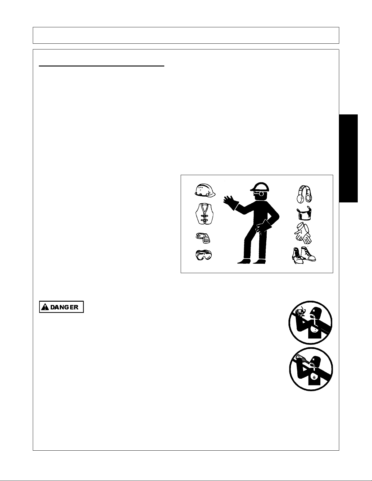
OPERATION
1.OPERATOR REQUIREMENTS
Safe operation of the unit is the responsibility of a qualified operator. A qualified operator has read and
understands the implement and tractor Operator’s Manuals and is experienced in implement and tractor
operation and all associated safety practices. In addition to the safety messages contained in this manual,
safety signs are affixed to the implement and tractor. If any part of the operation and safe use of this
equipment is not completely understood, consult an authorized dealer for a complete explanation.
If the operator cannot read the manuals for themselves or does not completely und erst and the opera tion of the
equipment, it is the responsibility of the supervisor to read and explain the manuals, safety practices, and
operating instructions to the operator.
Safe operation of equipment requires that the operator wear approved Personal Protective Equipment (PPE)
for the job conditions when attaching, operating, servicing, and repairing the equipment. PPE is designed to
provide operator protection and includes the following safety wear:
PERSONAL PROTECTIVE EQUIPMENT (PPE)
• Always Wear Safety Glasses
•Hard Hat
• Steel Toe Safety Footwear
• Gloves
• Hearing Protection
• Close Fitting Clothing
• Respirator or Filter Mask (depends on
operating conditions)
(OPS-U- 0002)
NEVER use drugs or alcohol immediately before or while operating the
Tractor and Implement. Drugs and alcohol will affect an operator’s
alertness and coordination and therefore affect the operator’s ability to
operate the equipment safely. Before operating the Tractor or Implement,
an operator on prescription or over-the-counter medication must consult
a medical professional regard ing any side effects of the medication that
would hinder their ability to operate the Equipment safely. NEVER
knowingly allow anyone to operate this equipment when their alertne ss or
coordination is impaired. Serious injury or death to the operator or others
could result if the operator is under the influen ce of drugs or a lcohol.
(SG-27)
OPERATION
Boom Operation Section 3-3
©2011 Alamo Group Inc.
Page 66

OPERATION
2.1 ROPS and Seat Belt
The tractor must be equipped with a Roll-Over-Protective-Structure (ROPS) (tractor cab or roll-bar) and seat
belt to protect the operator from falling off the tractor, especially during a roll over where the driver could be
crushed and killed. Only operate the tractor with the ROPS in the raised position and seat belt fastened.
Tractor models not equipped with a ROPS and seat belt should have these life saving features installed by an
authorized dealer. OPS-U- 0003
Operate this Equipment only with a Tractor equipped with an approved rollover-protective system (ROPS). Always wear seat belts. Serious injury or
even death could result from falling off the tractor--particularly during a turnover
when the operator could be pinned under the ROPS.
(SG-7)
2.2 Operator Thrown Object Protection
The tractor must be equipped with protective
equipment to shield the operator from falling and
thrown objects. For cab tractors, the tractor must
be equipped with an operator safety screen on its
right side or the right side windows must be fitted
with a shatter resistant safety window. For noncab tractors, the tractor must be eq uipped with a
ROPS and operator protective safety cage that
provides protection to the right and above the
operator seat. DO NOT remove the ROPS from
non-cab tractors to equip a safety cage.
OPS-B- 0001
2.TRACTOR REQUIREMENTS
In addition to tractor horsepower and size required to operate the boom unit, the tractor must also be properly
equipped to provide operator protection, to alert approaching vehicle drivers of the tractor’s presence, and to
ensure tractor stability when mowing with the boom fully extended.
Tractor Requirements and Capabilities
• ASAE approved Roll-Over Protective Structure (ROPS) or ROPS cab and seat belt.
• Operator Protection..........................Tractor must be equipped with protective structure such as
operatorcage or lexan window to protect operator from thrown object and falling objects
• Tractor Safety Devices ....................Slow Moving Vehicle (SMV) emblem, lighting,
• Tractor Ballast .................................As required to maintain at least 1500 lbs. on left rear tire
OPERATION
Boom Operation Section 3-4
©2011 Alamo Group Inc.
Page 67

OPERATION
Never operate the Tractor and Mower Unit without an OPS (Operators
Protective Structure) or Cab to prevent injury from objects thrown from
ground or from overhead trimming. Stop mowing if workers or passersby
are within 300 feet.
(SBM-9)
2.3 T ractor Lighting and SMV Emblem
If the tractor will be operated near or traveled on a
public roadway it must be equipped with proper
warning lighting and a Slow Moving Vehicle (SMV)
emblem which are clearly visible from the rear of
the unit. Most tractor’s have different settings for
operating and transporting lighting. Refer to the
tractor operator’s manual for using the tractor’s
light switch and operating the turn signals.
OPS-B- 0017
OPERATION
Boom Operation Section 3-5
©2011 Alamo Group Inc.
Page 68

OPERATION
2.4 T ractor Ballast
To ensure tractor stability when operating on flat surfaces the left rear tractor tire MUST exert a minimum
down force (weight) of 1500 lbs. on the ground when the tractor is on level ground, its boom is fully extended
and the mower head is horizontal and two feet above the ground. For units which have the ability to operate
on either side of the tractor, these requirements must also be met f or the right side tire when the boom is
extended to the left side as described above. A tractor that does not meet this criteria is DANGEROUS and
should not be operated as upset of the unit can occur resulting in possible serious injury and property
damage. NOTE: All factory mounted units are tested and meet the ballast requirement before shipment;
further testing is not required unless the unit is operated in a manner other than what is considered standard
operating conditions.
If the unit is operated on slopes greater than 5°,
additional counterweight will be required.
Operation of the unit on slopes greater than 11
percent (6.4 degrees) is not recommended under
any circumstances. On a tractor with a 96” outside
to outside tire spread, an 11 percent (6.4 degrees)
slope occurs when one rear tractor tire is about 8”
lower than the other rear tire. OPS-B- 0018
3.GETTING ON AND OFF THE TRACTOR
Before getting onto the tractor, the operator must read and completely understand the implement and tractor
operator manuals. If any part of either manual is not completely understood, consult an authorized dealer for
a complete explanation. OPS-U- 0007
Do not mount or dismount the Tractor while the tractor is moving. Mount
the Tractor only when the Tractor and all moving parts are completely
stopped.
(SG-12)
OPERATION
Boom Operation Section 3-6
©2011 Alamo Group Inc.
Page 69

OPERATION
3.1 Boarding the Tractor
Use both hands and equipped handrails and steps for support when boarding the tractor. Never use control
levers for support when mounting the tractor. Seat yourself in the operator’s seat and secure the seat belt
around you.
Never allow passengers to ride on the tractor or attached equipment. Riders can easily fall off and be
seriously injured or killed from falling off and being ran over. It is the operator’s responsibility to forbid all extra
riders at all times. OPS-U- 0008
Never allow children to operate, ride on, or come close to the Tractor or
Implement. Usually, 16-17 year-old children who are mature and
responsible can operate the implement with adult supervision, if they
have read and understand the Operator’s Manuals, been trained in
proper operation of the tractor and Implement, and are physically large
enough to reach and operate the controls easily.
(SG-11)
Never allow children or other persons to ride on the Tracto r or Implement.
Falling off can result in serious injury or death.
(SG-10)
Do not mount or dismount the Tractor while the tractor is moving. Mount
the Tractor only when the Tractor and all moving parts are completely
stopped.
(SG-12)
3.2 Dismounting the Tractor
Before dismounting the tractor, idle the tractor engine down, disengage the head and retract the boom arm to
the transport position. Park the tractor on a level surface, place the transmission in neutral and set the
parking brake. Shut down the tractor engine, remove the key, and wait for all motion to come to a complete
stop before exiting the operator’s seat. NEVER leave the seat until the tractor, its engine, and mower head
movement have come to a complete stop.
Use hand rails and extra steps when exiting the tractor. Be careful of your step and use extra caution when
mud, ice, snow, and other matter has accumulated on the steps and handrails. Never rush or jump off the
tractor. OPS-B- 0002
BEFORE leaving the tractor seat, always set the parking brake and/or set
the tractor transmission in parking gear, disengage the PTO, stop the
engine, remove the key, and wait for all moving parts to stop. Place the
tractor shift lever into a low range or parking gear to prevent the tractor
from rolling. Never dismount a Tractor that is moving or while the engine
is running. Operate the Tractor controls from the tractor seat only.
(SG-9)
OPERATION
Boom Operation Section 3-7
©2011 Alamo Group Inc.
Page 70

OPERATION
4.STARTING THE TRACTOR
The operator must have a complete understanding of the placement, function, and operational use of all
tractor controls before starting the trac tor. Review the tractor operator’s manual and consult an authorized
dealer for tractor operation instructions if needed.
Essential Tractor Controls:
• Locate the ignition key/switch
• Locate the engine shut off control
• Locate the hydraulic control levers
• Locate the light control lever
• Locate the brake pedals and clutch
• Locate the PTO control
• Locate the 3 point hitch control lever
• Locate the boom operating controls (joystick or valve bank)
Before starting the tractor ensure the following:
• Conduct all pre-start operation inspection and service according to the tractor operator’s manual.
• Make sure all guards, shields, and other safety de vices are securely in place.
• The parking brake is on.
• The tractor transmission levers are in park or neutral.
• The boom operating controls are in the neutral and off position.
• The PTO control lever is disengaged.
• The hydraulic remote control levers are in the neutral position.
Refer to the tractor owner’s manual for tractor starting procedures. Only start the tractor while seated and
belted in the tractor operator’s seat. Never bypass the ignition switch by short circuiting the starter solenoid.
After the tractor engine is running, avoid accidental contact with the tractor transmission to prevent sudden
and unexpected tractor movement. OPS-B- 0003
Never run the Tractor engine in a closed building or without adequate ventilation. The
exhaust fumes can be hazardous to your health.
(SG-23)
Start tractor only when properly seated in the Tractor seat. Starting a
tractor in gear can result in injury or death. Read the Tractor operators
manual for proper starting instructions.
(SG-13)
OPERATION
Boom Operation Section 3-8
©2011 Alamo Group Inc.
Page 71
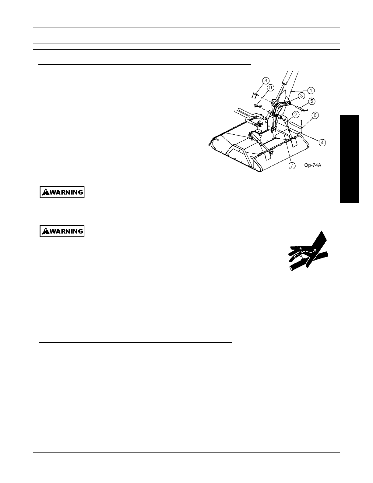
OPERATION
Avoid contact with hot surfaces including hydraulic oil tanks, pumps, motors, valves and
hose connections. Relieve hydraulic pressure before performing maintenance or repairs.
Use gloves and eye protection when servicing hot components. Contact with a hot surface
or fluid can cause serious injury from burns or scalding.
(SG-34)
Do not operate this Equipment with hydraulic oil or fuel leaking. Oil
and fuel are explosive and their presence could present a hazard. Do
not check for leaks with your hand! High-pressure oil streams from
breaks in the line could penetrate the skin and cause tissue damage
including gangrene. To check for a hose leak, SHUT the unit ENGINE
OFF and remove all hydraulic pressure. Wear oil imp ene trab le glo ves ,
safety glasses and use Cardboard to check for evidence of oil leaks. If
you suspect a leak, REMOVE the HOSE and have it tested at a Dealer.
If oil does penetrate the skin, have the injury treated immediately by a
physician knowledgeable and skilled in this procedure.
(SG-15)
6.PRE-OPERATION INSPECTION AND SERVICE
Before each use, a pre-operation inspection and service of the implement and tractor must be performed.
This includes routine maintenance and scheduled lubrication, inspecting that all safety devices are equipped
and functional, and performing needed repairs. DO NOT operate the unit if the pre-operation inspection
reveals any condition affecting safe operation. Perform repairs and replacement of damaged and missing
parts as soon as noticed. By performing a thorough pre-operation inspection and service, valuable down time
and repair cost can be avoided. OPS-U-0029
5.CONNECTING ATTACHING HEADS TO THE BOOM
1. Start by attaching the pivot bracket(3) to the boom(1)
using pin(5) and hardware. Next attach the cylinder to the
pivot bracket(3) using pin(8) and roll pins.
2. Then attach the dogleg(4) to the mower(2) using pin(7)
and hardware.
3. Use a hoist to lower the boom(1) down to the mower(2).
Insert the upper pin(6) through the end of the bo om and the
mower. Att ach with hardware.
4. Then align the dogleg(4) and the pivot bracket(3). Attach
with pin(9) and hardware.
5. Finally make sure all bolts, nuts, and pins are tightened to
recommended torque. OPS-B- 0004_D
OPERATION
Boom Operation Section 3-9
©2011 Alamo Group Inc.
Page 72

OPERATION
Periodically inspect all moving parts for wear and replace when
necessary with authorized service parts. Look for loose fasteners, worn
or broken parts, and leaky or loose fittings. Make sure all pins have
attaching hardware. Serious injury may occur from not maintaining this
machine in good working order.
(SG-21_A)
All Safety Shields, Guards and Safety devices including (but not
limited to) - the Deflectors, Chain Guards, Steel Guards, Gearbox
Shields, PTO integral shields, and Retractable Door Shields should
be used and maintained in good working condition. All safety devices should be
inspected carefully at least daily for missing or broken components. Missing, broken,
or worn items must be replaced at once to reduce the possibility of injury or death
from thrown objects, entanglement, or blade contact.
(SGM-3)
6.1 Tractor Pre-Operation Inspection/Service
Refer to the tractor operator’s manual to ensure a
complete pre-operation inspection and scheduled
service is performed according to the
manufacturers recommendations. The following
are some of the items that require daily service and
inspection:
• Tire cond ition/air pressure
• Wheel lug bolts
• S teering linkage
• PTO shield
• SMV sign is clean and visible
• Tractor’s lights are clean and functional
• Tractor Seat belt is in good condition
• Tractor ROPS is in good condition
• ROPS is in the raised position
• No tractor oil leaks
• Radiator free of debris
• Engine oil level and condition
• Engine coolant level and condition
• Power brake fluid level
• Power steering fluid level
• Fuel condition and level
• Sufficient lubrication at all lube points
• Air filter condition OPS-U-0030
OPERATION
Boom Operation Section 3-10
©2011 Alamo Group Inc.
Page 73

OPERATION
Periodically inspect all moving parts for wear and replace when
necessary with authorized service parts. Look for loose fasteners, worn
or broken parts, and leaky or loose fittings. Make sure all pins have
attaching hardware. Serious injury may occur from not maintaining this
machine in good working order.
(SG-21_A)
The operator’s manual and safety signs affixed on
the unit contain important instructions on the safe
and proper use of the equipment. Maintain these
important safety features on the implement in good
condition to ensure the information is available to
the operator at all times.
• Ensure all safety signs are in place and legible.
Replace missing, damaged, and illegible
decals. OPS-U- 0011_A
Turret Frame Assy.
6.2 Boom Unit Pre-Operation Inspection and Service
Inspect and service the boom arm and head prior to operation. Damaged and/or broken parts should be
repaired and/or replaced immediately. To ensure the unit is ready for operation, conduct the following:
OPS-B- 0020
OPERATION
FRAME ASSEMBLY
• Inspect condition of mounting frame weldment.
• Inspect condition of Swivel Assy.
• Ensure all bolts and screws are in position and
are properly torqued.
• Ensure all pins are in place and fastened with
screws.
• Ensure frame is properly mounted to tractor
and hardware is propely installed and
tightened. OPS-B- 0021_D
Boom Operation Section 3-11
©2011 Alamo Group Inc.
Page 74

OPERATION
Relieve hydraulic pressure prior to doing any maintenance or repair work on the Implement.
Place the Mower Head on the ground or securely supported on blocks or stands, disengage
the PTO, and turn off the engine. Push and pull the control Le vers or Joystick several times
to relieve pressure prior to starting any maintenance or repair work.
(SBM-6)
Never Leave the mower unattended while the head is in the raised
position. The mower could fall causing serious injury to anyone who
might inadvertently be under the mower
. (SBM-4)
BOOM ARM ASSEMBLY
• Inspect condition of each arm section weldment
• Ensure all pins are in place.
• Ensure all bolts, nuts and rollpins are properly
installed.
• Check condition of bushings at boom pivot
points and hydraulic cylinder tangs.
• Ensure each hydraulic cylinder is installed and
retained correctly. Ensure the proper size pins
are used to retain the cylinders in place and ar e
secured properly. OPS-B- 0022_D
Never attempt to lubricate, adjust, or remove material from the Implement while it is in
motion or while tractor engine is running.
(SG-20)
HYDRAULIC LINE INSPECTION
• Check for hydraulic leaks along hoses,
cylinders and fittings. IMPORTANT: DO NOT
use your hands to check for oil leaks. Use a
piece of heavy paper or cardboard to check for
hydraulic oil leaks.
• Inspect the condition of the valve mounting.
• Ensure fittings are properly connected.
OPS-B- 0023_D
OPERATION
Boom Operation Section 3-12
©2011 Alamo Group Inc.
Page 75

OPERATION
Do not operate this Equipment with hydraulic oil or fuel leaking. Oil
and fuel are explosive and their presence could present a hazard. Do
not check for leaks with your hand! High-pressure oil streams from
breaks in the line could penetrate the skin and cause tissue damage
including gangrene. To check for a hose leak, SHUT the unit ENGINE
OFF and remove all hydraulic pressure. Wear oil imp ene trab le glo ves ,
safety glasses and use Cardboard to check for evidence of oil leaks. If
you suspect a leak, REMOVE the HOSE and have it tested at a Dealer.
If oil does penetrate the skin, have the injury treated immediately by a
physician knowledgeable and skilled in this procedure.
(SG-15)
HYDRAULIC PUMP/OIL RESERVOIR
• Check oil reservoir level and oil condition. (Add
specific type oil if low)
• Change hydraulic oil filter and hydraulic oil
according to maintenance schedule.
• Ensure there are no oil leaks and fitting are
properly connected
• Inspect overall condition of hydraulic pump.
• Inspect pump drive shaft.
Check the fluid level in the Hydraulic Tank on the
Tractor, and add oil if required. As the air has been f orced out of the Cylinders and Hoses, it go es into the
Hydraulic Tank and reduces the volume of oil. Maintain the oil level within the sight gauge located on the side
of the reservoir. Never fill the tank above the sight gauge to allow for the expansion of the oil. The tank
maintains pressure after the mower has been run. Stand off to one side when removing the breather cap
element to prevent possible injury. OPS-B 0024_E
Attention: Oil Filler Cap is also the Pressure Relief Cap.
Remove cap slowly to relieve pressure before removing cap completely. Stay clear to
prevent being scalded with hot oil that may spray out of the tank that is still pressurized and
may cause serious injury to eyes, face, and exposed skin.
(Ops-0001-MISC)
Avoid contact with hot surfaces including hydraulic oil tanks, pumps, motors, valves and
hose connections. Relieve hydraulic pressure before performing maintenance or repairs.
Use gloves and eye protection when servicing hot components. Contact with a hot surface
or fluid can cause serious injury from burns or scalding.
(SG-34)
OPERATION
Boom Operation Section 3-13
©2011 Alamo Group Inc.
Page 76

OPERATION
ROTARY HEAD INSPECTION
• Inspect blades and blade bolts for looseness
and excessive wear. Rotate to 90° to make
for checking easier . Replace damaged, worn,
and missing blades as complete sets to
maintain rotary balance.
• Ensure motor bolts and nuts are tightened to
the appropriate torque.
• Ensure rubber deflectors are in position and
not damaged. Replace worn, broken, and
missing sections immediately.
• Ensure hydraulic lines are properly connected
to the hydraulic motor. Check for hydrau lic
leaks along hoses and fittings. DO NOT use
your hands to check for oil leaks. Use a piece
of heavy paper or cardboard to check for
hydraulic oil leaks.
• Inspect the condition of deck skid shoes and hardware. OPS-B- 0025
Do not put hands or feet under mower decks. Blade Contact can result
in serious injury or even death. Stay away until all motion has stopped
and the decks are securely blocked up.
(SGM-09)
All Safety Shields, Guards and other safety devices including (but not limited to) Deflectors, Steel Guards and Gearbox Shields must be used and maintained in good
working condition. All safety devices should be inspected carefully at least daily for missing
or broken components. Missing, broken, or worn items must be replaced at once to reduce
the possibility of injury or death from thrown objects, entanglement, or blade contact.
(SSM-07)
OPERATION
Boom Operation Section 3-14
©2011 Alamo Group Inc.
Page 77

OPERATION
and excessive wear . Rotate to 90° to make for
checking easier . Replace damaged, worn, and
missing blades as complete sets to maintain
cuttershaft balance.
not damaged. Replace worn, broken, and
missing sections immediately.
rotate freely.
and are properly torqued.
to the hydraulic motor. Check for hydraulic
leaks along hoses and fittings. DO NOT use
your hands to check for oil leaks. Use a piece
of heavy paper or cardboard to check for
hydraulic oil leaks.
in good repair.
be wrapped around the cuttershafts ends.
hardware. OPS-B- 0026_B
Do not put hands or feet under mower decks. Blade Contact can result
in serious injury or even death. Stay away until all motion has stopped
and the decks are securely blocked up.
(SFL-2)
All Safety Shields, Guards and other safety devices including (but not limited to) Deflectors, Steel Guards and Gearbox Shields must be used and maintained in good
working condition. All safety devices should be inspected carefully at least daily for missing
or broken components. Missing, broken, or worn items must be replaced at once to reduce
the possibility of injury or death from thrown objects, entanglement, or blade contact.
(SSM-07)
OPERATION
Boom Operation Section 3-15
©2011 Alamo Group Inc.
Page 78

OPERATION
6.3 Cutting Component Inspection
Inspect blade pan and blade assembly for the following: OPS-U-0031
Inspect the Blades daily for abnormal wear. REPLACE BOTH BLADES on that carrier
IMMEDIATELY if either blade has:
• Become bent or deformed from it’s original shape or
• Any cracks are visible, or
• Deep gouges in the blade’ s surface are present, or
• Gouges or chipped areas in the cutting edge are larger than 1/2”(12.7mm), or
• The material on the leading edge has been worn away by more than 1/2(12.7mm)”
Failure to replace abnormally worn blades may lead to catastrophic failure of the blades and ejection of the
broken part with tremendous force which may cause serious bodily injury or death. OPS-U-0032
OPERATION
Boom Operation Section 3-16
©2011 Alamo Group Inc.
Page 79

OPERATION
Tractor PRE-OPERATION Inspection
Mower ID#________________ Make ____________________
Date: ________________ Shift ____________________
Before conducting the inspection, make sure the tractor engine is off, all rotation
has stopped and the tractor is in park with the parking brake engaged. Make sure
the mower is resting on the ground or securely blocked up and all hydraulic
pressure has been relieved.
Operator’s Signature:
Item
Condition at Start
of Shift
Specific Comments
if not O.K.
The flashing lights function properly
The SMV Sign is clean and visible
The tires are in good condition with proper pressure
The wheel lug bolts are tight
The tractor brakes are in good condition
The steering linkage is in good condition
There are no visible oil leaks
The hydraulic controls function properly
The ROPS or ROBS Cab is in good condition
The seatbelt is in place and in good condition
The 3-point hitch is in good condition
The drawbar pins are securely in place
The PTO master shield is in place
The engine oil level is full
The brake fluid level is full
The power steering fluid level is full
The fuel level is adequate
The engine coolant fluid level is full
The radiator is free of debris
The air filter is in good condition
DO NOT OPERATE an UNSAFE TRACTOR or MOWER
This Inspection Form may be freely duplicated for extra copies.
OPERATION
Boom Operation Section 3-17
©2011 Alamo Group Inc.
Page 80

OPERATION
Boom PRE-OPERATION Inspection
Mower ID#________________ Make ____________________
Date: ________________ Shift ____________________
Before conducting the inspection, make sure the tractor engine is off, all rotation has
stopped and the tractor is in park with the parking brake engaged. Make sure the
mower is resting on the ground or securely blocked up and all hydraulic pressure has
been relieved.
Operator’s Signature:
Table 1:
Item
Condition at Start
of Shift
Specific Comments
if not O.K.
The Operator’s Manual is in the tractor
All safety decals are in place and legible
The mounting frame bolts are in place and tight
The boom connection bolts & pins are tight
There are no cracks in boom
The hydraulic cylinders pins are tight
The hydraulic pump hose connections are tight
The hydraulic valve controls function properly
There are no leaking or damaged hoses
The hydraulic oil level is full
There is no evidence of hydraulic leaks
The blades are not chipped, cracked or bent
The blade bolts are tight
The deflectors are in place and in good condition
The boom shields are in place and in good condition
The skid shoes are in good condition and tight
There are no cracks or holes in boom deck
The hydraulic motor mounting bolts are tight
The boom head spindle housing is tight and lubricated
DO NOT OPERATE an UNSAFE TRACTOR or MOWER
OPERATION
Boom Operation Section 3-18
©2011 Alamo Group Inc.
Page 81

OPERATION
Cable Controlled Mowers
A control lever decal similar to the one shown below should be near the control valve to remind the operator of
the lever functions.
The main control valve on the Tiger Boom Mower
has four sections with tapered spools, located near
the right side of the stee ring wheel. The malfun ction
of a section of the valve does not necessitate the
replacement of the entire “bank”, only the faulty
section. Each section of the valve controls a certain
position of the boom or deck. Seated in the operators
seat, the controls from left to right are #1-primary
(main) boom, #2-secondary boom, #3 -deck roll, #4boom (swivel) swing), and #5- boom (safety) shield.
OPERATION
Boom Operation Section 3-19
©2011 Alamo Group Inc.
Page 82

6.4 Switchbox
The Safety Shield lever opens and closes the shield
located on the front of the cutter head. When moving
at or near the ground, always have the shield in th
closed position. When mowing in the brush or in
trees above ground level the shield may be opened
for easier cutting. Read and follow the warnings on
the decal shown below. Do not run the cutter head
into material larger than 6” diameter.
OPERATION
OPERATION
Boom Operation Section 3-20
©2011 Alamo Group Inc.
Page 83

LEVER #1 MAIN BOOM
LEVER #2 SECONDARY BOOM
OPERATION
OPERATION
LEVER #3 DECK ROLL
Boom Operation Section 3-21
©2011 Alamo Group Inc.
Page 84

LEVER #4 BOOM SWIVEL
LEVER #5 BOOM SHIELD
OPERATION
OPERATION
Boom Operation Section 3-22
©2011 Alamo Group Inc.
Page 85

OPERATION
7.Joystick Controlled Mowers
NOTE: DO NOT operate mower head while boom mower is in the boom rest, or in the stored
position! Red “Mower Run” light indicates mower is “ON”.
The boom functions are controlled by an electronic joystick. The Joystick Master Switch enables the joystick
control for controlling the boom motion functions. This switch is to be in the “OFF” position when starting the
tractor and when boom is stowed for transporting the machine.
If the joystick control is not operating properly, turn the master switchto the “OFF” position.
Install the manual valve handle onto valve and operate the functions individually to stow boom.
After boom is stowed in rest, transport the unit to the maintenance facility and contact your
Tiger dealer for assistance.
DO NOT attempt to operate the valve manually for mowing operations!
Note: Pushing manual valve handles “out” or “away” from the tractor cab will bring the main
boom “up”, secondary boom “out”, roll deck “out”, and swivel boom “aft”. Pulling manual handles toward cab
will let main boom “down”, bring secondary boom “in”, roll deck “in”, and swivel boom “forward”.
OPERATION
Boom Operation Section 3-23
©2011 Alamo Group Inc.
Page 86

OPERATION
7.1 Switch Box and Joystick Control
The diagrams below and on the next page show the functions that are performed through the use of the
joystick controller.
OPERATION
The Safety Shield switch opens and closes the shield located on the front of the cutter head. When moving at
or near the ground, always h ave the shield in the closed position. When mo ving in brush or in trees above
ground level the shield may be opened for easier cutting. Read and follow the warnings on the decal shown
below. Do not run the cutter into material larger than 6” diameter.
Boom Operation Section 3-24
©2011 Alamo Group Inc.
Page 87

Joystick Control
OPERATION
OPERATION
JOYSTICK FWD/BACK MOVES MAIN BOOM
Boom Operation Section 3-25
©2011 Alamo Group Inc.
Page 88

JOYSTICK LEFT/RIGHT MOVES SECONDARY
BOOM
LEFT JOYSTICK ROLLER MOVES DECK ROLL
OPERATION
OPERATION
RIGHT JOYSTICK ROLLER MOVES BOOM
SWIVEL
Boom Operation Section 3-26
©2011 Alamo Group Inc.
Page 89

OPERATION
8.DRIVING THE TRACTOR AND IMPLEMENT
Safe tractor transport requires the operator to possess a thorough knowledge of the model being operated
and precautions to take while driving with an attached implement. Ensure the tractor has the capacity to
handle the weight of the boom and the tractor operating controls are set for safe transport. To ensure safety
while driving the tractor with a boom, review the following.
Read all safety instructions. Decals on the Boom warn you of particular and multiple hazards. Some decals
are attached close to part of the Boom where there is a possible hazard. Read and make sure you
understand the safety messages before you operate the implement. Keep all decals clean and readable.
Replace lost or damaged decals, refer to safety section for more information.
Keep all person's well clear of mower since blades can throw objects with great velocity for a considerable
distance! KEEP CLEAR! OPS-B- 0005
RIGHT JOYSTICK ROLLER WHILE PRESSING
BUTTON MOVES BOOM KNUCKLE ON A LEGAL
REAR STOW BOOM
SHIELD SWITCH(on switch box) OPERATES
SAFETY SHIELD
OPERATION
Boom Operation Section 3-27
©2011 Alamo Group Inc.
Page 90

OPERATION
Never operate the Tractor or Implement until you have read and
completely understand this Manual, the Tractor Operator’s Manual, and
each of the Safety Messages found in the Manual or on the Tractor and
Implement. Learn how to stop the tractor engine suddenly in an
emergency. Never allow inexperienced or untrained personnel to operate
the Tractor or Implement without supervision. Make sure the operator
has fully read and understood the manuals prior to operation.
(SG-4)
Always maintain the safety signs in good r eadable condition. If the safety signs are missing,
damaged, or unreadable, obtain and install replacement safety signs immediately.
(SG-5)
BEFORE leaving the tractor seat, always set the parking brake and/or set
the tractor transmission in parking gear, disengage the PTO, stop the
engine, remove the key, and wait for all moving parts to stop. Place the
tractor shift lever into a low range or parking gear to prevent the tractor
from rolling. Never dismount a Tractor that is moving or while the engine
is running. Operate the Tractor controls from the tractor seat only.
(SG-9)
OPERATION
Boom Operation Section 3-28
©2011 Alamo Group Inc.
Page 91

OPERATION
Transport only at speeds where you can maintain control of the
equipment. Serious accidents and injuries can result from operating this
equipment at high speeds. Understand the Tractor and Implement and
how it handles before transporting on streets and highways. Make sure the Tractor steering
and brakes are in good condition and operate properly.
Before transporting the Tractor and Implement, determine the proper transport speeds for
you and the equipment. Make sure you abide by the following rules:
Test the tractor at a slow speed and increase the speed slowly. Apply the Brakes smoothly
to determine the stopping characteristics of the Tractor and Implement. As you increase
the speed of the Tractor the stopping distance increases. Determine the maximum
transport speed not to exceed 20 mph (30 kph) for transporting this equipment.
Test the equipment at a slow speed in turns. Increase the speed through the turn only after
you determine that the equipment can be operated at a higher speed. Use extreme care
and reduce your speed when turning sharply to prevent the tractor and implement from
turning over. Determine the maximum turning speed for you and this equipment before
operating on roads or uneven ground.
Only transport the Tractor and Implement at the speeds which allow you to properly control
the equipment.
Be aware of the operating conditions. Do not operate the Tractor with weak or faulty brakes
or worn tires. When operating down a hill or on wet or rain slick roads, the braking distance
increases: use extreme care and reduce you r speed. When operating in traf fic always use
the Tractor’s flashing warning lights and red uce your speed. Be a ware of traf fic around yo u
and watch out for the other guy.
(SG-19)
8.1 Starting the Tractor
The procedure to start the tractor is model specific.
Refer to the tractor operator’s manual for starting
procedures for your particular tractor. Consult an
authorized dealer if the starting procedure is
unclear. Ensure the 3-point control lever is in the
lowered position and the PTO is disengaged before
starting the tractor. OPS-U-0033
OPERATION
Boom Operation Section 3-29
©2011 Alamo Group Inc.
Page 92

OPERATION
8.2 Brake and Differential Lock Setting
Make sure the tractor brakes are in good operating
condition. Tractor brakes can be set to operate
independently allowing single rear wheel braking
action or locked together to provide simultaneous
rear wheel braking. FOR MOST DRIVING AND
OPERATING CONDITIONS, THE BRAKE PEDALS
SHOULD BE LOCKED TOGETHER TO PROVIDE
THE MOST EFFECTIVE BRAKING ACTION.
Always disengage the tractor differential lock when
turning. When engaged the differential lock will
prevent or limit the tractor from turning. During
normal cutting conditions, locking the differential
provides no benefit and should not be used.
OPS-U- 0013
Be aware of the operating conditions. Do not operate the Tractor with weak or faulty brakes.
When operating down a hill or on wet or rain slick roads, the braking distance increases;
use extreme care and reduce your speed in these conditions. When operating in traffic,
always use the Tractor’s flashing warning lights and reduce your speed. Be aware of traffic around you and
watch out for the other guy.
(Ops-0004-MISC)
BEFORE leaving the tractor seat, always set the parking brake and/or set
the tractor transmission in parking gear, disengage the PTO, stop the
engine, remove the key, and wait for all moving parts to stop. Place the
tractor shift lever into a low range or parking gear to prevent the tractor
from rolling. Never dismount a Tractor that is moving or while the engine
is running. Operate the Tractor controls from the tractor seat only.
(SG-9)
OPERATION
Boom Operation Section 3-30
©2011 Alamo Group Inc.
Page 93

OPERATION
8.3 Driving the Tractor and Boom
Start off driving at a slow speed and gradually increase your speed while maintaining complete control of the
tractor. Never operate the tractor at speeds that cannot be safely handled or which will prevent the operator
from stopping quickly during an emergency. If the power steering or engine ceases operating, stop the tractor
immediately as the tractor will be difficult to control.
Perform turns with the tractor and mower at slow
speeds to determine how the tractor with and
attached implement handles a turn. Determine the
safe speed to maintain proper control of the tractor
when making turns. When turning with the
implement the overall working length and width of
the unit is increased. Allow additional clearance for
the unit when turning or when passing large
obstructions.
To avoid overturns, drive the tractor with care and
at safe speeds, especially when operating over
rough ground, crossing ditches or slopes, and
turning corners. Use extreme caution when
operating on steep slopes. Keep the tractor in a low
gear when going downhill. DO NOT coast or freewheel downhill.
OPS-B- 0006
OPERATION
Boom Operation Section 3-31
©2011 Alamo Group Inc.
Page 94

OPERATION
Never Leave the mower unattended while the head is in the raised
position. The mower could fall causing serious injury to anyone who
might inadvertently be under the mower
. (SBM-4)
Always keep a careful lookout and use extreme care when working
around overhead obstructions. Never allow the Mower head or boom
within 10 feet of any power line. When working close to overhead
power lines consult your electric company for a safe code of operation.
(SBM-7)
9.OPERATING THE BOOM UNIT AND ATTACHED HEAD
THE OPERATOR MUST COMPLETELY UNDERSTAND HOW TO OPERATE THE TRACTOR AND
MOWER AND ALL CONTROLS BEFORE ATTEMPTING T O MOW. The operator must read and understand
the Safety and Operation Sections of this manual and the tractor operator’s manuals. These manuals must
be read and explained to any operator who cannot read. Never allow someone to operate the unit without
complete operating instructions.
To ensure safety to the operator, bystanders, and equipment and before starting any mowing operation. The
operator must become familiar with the area to be mowed, and any obstacles and hazards contained within.
Special attention should be paid to foreign debris, overhead obstructions, rough terrain, steep slopes,
passersby and animals in the area.
Only operate the mower head from the tractor operator’s seat with the seatbelt securely fastened. Only
operate a boom and equipped head on cabbed tractor that is eq uipped with a polycarbonate safety-protected
right side window or a non cabbed tractor equipped with a ROPS and operator safety screen.
Avoid operating in the reverse direction when possible. In situations where the boom and mower must be
backed to access areas to be cut, make sure there are no persons or other foreign debris behind the tractor.
When backing, operate the tractor at a much reduced ground speed to ensure complete control of the unit is
maintained. OPS-B- 0007
Do not mow with two machines in the same area except with Cab tractors with the windows
closed.
(SGM-11)
Mow only in conditions where you have clear visibility in daylight or with adequate artificial
lighting. Never mow in darkness or foggy conditions where you cannot clearly see at least
300 feet (90 m) in front and to the sides of the tractor and mower. Make sure that you can
clearly see and identify passersby, steep slopes, ditches, drop-offs, overhead obstructions,
power lines, debris and foreign objec ts. If you are unab le to clear ly see thes e type of ite ms
discontinue mowing.
(SGM-01)
OPERATION
Boom Operation Section 3-32
©2011 Alamo Group Inc.
Page 95

OPERATION
Avoid mowing in reverse direction when possible. Check to make sure there are no
persons behind the mower and use extreme care when mowing in reverse. Mow only at a
slow ground speed where you can safely operate and control the tractor and mower.
Never mow an area that you have not inspected and removed debris or foreign material.
(SGM-08)
Never operate the mower head tilted down where the operator can see the blades of the
mower. The blade could throw an object toward the operator causing serious injury or
death. Never operate the mower without an Operator Protective Structure. Always wear
safety glasses and a hard hat. (Ops-0005-MISC)
9.1 Foreign Debris Hazards/Overhead Obstructions
An area to be cut must first be inspected for objects that could be thrown or that could damage the machine.
Walk through the area looking for fences, boulders, rocks, culverts, stumps or metal objects. Mark the
inspected area with flags. If the area is dense and cannot be walked thoro ug hly it may b e necessar y to in sp ect
a smaller area as well as possible, then trim away the part that has been inspected and can safely be
removed. Walk each new area again and repeat the inspection before cutting more away. Repeat as often as
necessary until the area is cleared. It can be damaging and/or d angerous to work the cutter in an area that has
not been visually inspected.
Place DANGER signs at least 300 feet beyond the perimeter of the area to be worked, not just 300 feet from
where the machine started operating! It is convenient in many cases to work in 300 foot sections. Move the
first Danger sign to the beginning of the freshly cleared area, place it, then take the first cutting area flag up to
the end of the freshly cleared area 300 feet away. Walk and inspect the next 300 feet and place the sec ond
cutting area flag. Pick up the second DANGER sign, and take it a further 300 feet along the road or trail. Note
that in many cases the DANGER area will extend in front of and behind the machine as well as along each
side. Post signs accordingly. OPS-B- 0008
Extreme care should be taken when operating near loose objects such
as gravel, rocks, wire, and other debris. Inspect the area before
mowing. Foreign objects should be removed from the site to prevent
machine damage and/or bodily injury or even death. Any objects that
cannot be removed must be clearly mark ed and car efully avo ide d b y th e
operator. Stop mowing immediately if blades strike a foreign object.
Repair all damage and make certain rotor or blade carrier is balanced
before resuming mowing.
(SGM-05)
Many varied objects, such as wire, cable, rope, or chains, can become entangled in the
operating parts of the mower head. These items could then swing outside the housing at
greater velocities than the blades. Such a situation is extremely hazardous and could result
in serious injury or even death. Inspect the cutting area for such objects before mowing.
Remove any like object from the site. Never allow the cutting blades to contact such items.
(SGM-06)
OPERATION
Boom Operation Section 3-33
©2011 Alamo Group Inc.
Page 96

OPERATION
Mow at the speed that you can safely operate and control the tractor and mower. The
correct mowing speed depends on terrain condition and grass type, density, and height of
cut. Normal ground speed range is from 2 to 5 mph(3-8 kph). Use slow mowing speeds
when operating on or near steep slopes, ditches, drop-offs, overhead obstructions, power
lines, or when debris and foreign objects are to be avoided.
(SGM-07)
9.2 Operating Speed and Ground Speed
Ground speed for mowing will depend upon the height, type, and density of vegetation to be cut. Do Not
exceed 5 MPH while operating. Operate the mower at its full rated PTO speed to maintain blade speed for a
clean cut. Refer to the tractor operator’s manual or the tractor instrument p an el for th e e ngi ne sp eed a nd gear
to provide the required operating and desired gr oun d speed. Make sure that the mower is operating at its full
rated speed before entering the vegetation to be cut. Always start and stop cutting blades with engine near
idle.
Ground speed is achieved by transmission gear selection and not by the engine operating speed. The
operator may be required to experiment with several gear range combinations to determine the be st gear and
range which provides the most ideal performance from the implement and most efficient tractor operation. As
the severity of cutting conditions increase, the ground speed should be decreased. OPS-B- 0009
Mow at the speed that you can safely operate and control the tractor and mower. The
correct mowing speed depends on terrain condition and grass type, density, and height of
cut. Normal ground speed range is from 2 to 5 mph(3-8 kph). Use slow mowing speeds
when operating on or near steep slopes, ditches, drop-offs, overhead obstructions, power
lines, or when debris and foreign objects are to be avoided.
(SGM-07)
9.3 Operating the Attached Mower Heads
The boom can attach to and operate multiple heads one at a time for a wide range of vegetation control
applications. The attached heads are designed for dif fer ent applications. The h ead should be selected based
on the mowing application and the location that the unit is being operated.
Refer to the Assembly Section of this manual to ensure the head is properly attached to the boom hitch and
hydraulic lines are properly connected. OPS-B- 0010
There are obvious and hidden potential hazards in the operation of this
Mower. REMEMBER! This machine is often operated in heavy brush
and in heavy weeds. The Blades of this Mower can throw objects if
shields are not properly installed and maintained. Serious injury or even
death may occur unless care is taken to insure the safety of the operator,
bystanders, or passersby in the area. Do not operate this machine with
anyone in the immediate area. Stop mowing if anyone is within 300 feet
of mower.
(SGM-02)
OPERATION
Boom Operation Section 3-34
©2011 Alamo Group Inc.
Page 97

OPERATION
9.4 Mower Operation
The rotating parts in this machine have been design ed and tested for rugged use. However, they could fail
upon impact with heavy solid objects-such as steel guard rails, concrete abutments,etc., causing th em to be
thrown at a very high velocity. Never allow cutter head to contact such objects. Inspecting the cutting area for
such objects and removing them prior to mowing can help eliminate these potiential hazards.
Once on location, lower the mower deck slightly above the material to be cut, so the mower does not have to
start under a load. With the tractor at an idle, engage mower. Bring tractor R.P.M. up to 1900-2200 R.P.M. and
slowly lower deck to ground level.
A flail mower deck should be carried so that the part of the deck weight is carried by the boom and part carried
by the ground roller, when moving on the ground. When the flail mower is carried this way, the ground roller
follows the contour of the ground more easily during mowing operations.
The rotary mower deck should always be carried rather th an dragged on the skid shoes when mowing on the
ground. Dragging the rotary mower deck increases the side loads on the boom, decreases the horsepower
available to the cutter head, and reduces the ability of the accumulator the carry par t of the we ight of the boo m
during mowing operations.
When rotating parts are in motion, serious injury may occur if caution is not used or danger is
not recognized. Never allow bystanders within 300 feet of the machine when in operation.
Extreme care should be taken when operating near loose objects-such as gravel, rocks, and
debris. These conditions should be avoided.
OPERATION
9.5 50” & 60” Boom Rotary
The 50” & 60” boom rotary brush mower was
designed for cutting brush and foliage up to 6
inches in diameter or multiple branches that have a
total cross section area equivalent to one 6 inch
branch.
During mower operation, the hand throttle must be
used to maintain engine speed at 190 0-2200 R.P.M.
This prevents radical changes in mower spindles
speed, reducing the possibility of cutter assembly
damage.
The horizontal positioning action of the boom is
designed to position the cutting head and provide a
limited pressure relief when excessive pressure is
applied to the boom. Do not force the cutting head
into heavy branches or stumps. Damage to the unit may result.
When using the rotary cutting head for trimmin g trees and shrubs, let the mower saw into them.
Do not lower the mower head down directly into a tree or stump. The mower blades are
designed to cut with the end, and misuse can cause damage to the blade and a hazardous
situation for the operator.
Powering the boom down, forcing mower deck onto ground may damage mower deck and it’s
attachment to the boom, creating a potentially hazardous situation.
To ensure a clean cut, engine speed should be maintained at approximately 1900-2200 R.P.M. If the tractor
slows to less than 1800 R.P.M., shift to the next lower gear. DO NOT ride the clutch, this will cause premature
clutch failure. The engine should not be operated at any time at more than 2400 R.P.M. on the tractor
tachometer.
Boom Operation Section 3-35
©2011 Alamo Group Inc.
Page 98

OPERATION
For cutting brush, it is usually best to stop the tractor and swivel the boom and mower into foilage. The
horizontal positioning action of the boom is designed to position the cutting head and provide a limited
pressure relief when excessive pressure is applied to the boom.
DO NOT use excessive force when positioning cutting head into heavy branches or stumps.
Damage to the unit may result. It is best to let the cutter head “eat away” slowly at heavy cutting
jobs.
If foliage falls on top of mower deck causing tractor to become unstable, move the boom
“Forward” and “Out” to relieve tipping of the tractor. Lower mower deck to ground and shut
down unit. After all motion stops, remove foliage from mower deck.
The mower will operate more efficiently in tougher conditions and with less power if the knives are kept sharp.
If the mower begins to vibrate, stop the tractor, check for wire wrapped in the spindle or damaged knives.
When replacing knives, replace all knives with new knives to ensure proper balance so the mower will not
vibrate. Severe vibration will result, if knives with unequal wear are used.
Begin a pass at the top side of the trees and work down with each consecutive pass. When cutting trees and
shrubs, use a lower speed to allow the knives time to cut as well as mulch the foliage.
OPERATION
If cutter shaft jams and stops, turn mower switch to “OFF”, and swivel boom “AFT”. Normally this action will
clear the cutter head. If not, roll mowe r deck until adjacent to the secondary boom, then lower boom to rest
mower deck on ground. Shut off the tractor, set parking break, allow all motion to cease. At that point it is safe
to leave the tractor and clear the cutter heads manually.
Begin each pass at the top side of the trees and work down with each consecutive pass. Use a low speed to
allow the cutting blades time to mulch as well as cut the foliage. When the initial pass has been made,
disengage the mower, and return boom to a safe travel position. Return to starting point and make next pass,
etc..
After the first day of operation, all bolts should be checked and tightened securely. This should be done
periodically to ensure the bolts do not b ecome loose and cause damag e to the tractor or mower, or injury to the
operator.
If bystanders approach within 300 feet while mower is in operation turn mower switch “OFF”
immediately! After shutdown, never leave the tractor or a llow bystander s to approach within 300
FEET of the unit until all motion stops completely.
Boom Operation Section 3-36
©2011 Alamo Group Inc.
Page 99

OPERATION
When cutting trees and brush approach material
to be cut with the head perpendicular to material.
The cutting edge of the blades should be the
only elements in contact with material. The blade
bar should not contact with material. The mower
head and blades should be moved
perpendicularly into the material rather lowering
the mower head on top of material. If the blade
bar edges are gouged or rounded from wear, the
mower head is being used incorrectly in an
abusive manner . The blad e bar is n ot intended to
cut material or to be a wear item like the blades.
Do Not allow the blades or blade bar to contact
the ground, rocks or solid objects. Contact with
the ground can result in rocks and solid objects
being thrown out from under the mower head
which can cause serious injuries to the operator
and bystanders. This type of operation can lead
to bent or broken blade bars, broken blade bolts
and broken blade bar assembly bolts which can
be dangerous to the operator and bystanders.
OPERATION
(OPS-R-220)
9.6 50” Boom Flail
The 50’ boom flail mower was designed for cutting
brush and foliage up to 3 inches in diameter or
multiple branches that have a total cross section
area equivalent to one 3 inch branch. Cutting
multiple limbs at the same time may overload the
mower causing it to slow down or stall completely.
Regardless of the size of material being cut, the
cutter shaft speed must be maintained. To ensure
that the cutter shaft is running at maximum speed,
run the tractor at full throttle during mowing
operations. If the cutter shaft slows to the point that
the knives are folding back, move the mower head
away from the foliage and allow the cutter shaft to
regain full speed.
Operating the mower in a manner that allows the knives to continually fold back or allowing
knive lugs to contact foliage will cause permanent damage to the cutter shaft drum, knives, and
knife attachment parts.
The 50” boom flail cutter shaft is designed for standard rotation (same rotation as the tractor
wheels during forward travel). Never operate the cutter shaft in reverse rotation. Operating
this mower in reverse rotation may cause objects to be thrown out the front of the mower head.
The 50” boom flail equipped with free swinging brush knives is intended for brush cutting only.
Cutting grass is not recommended.
Boom Operation Section 3-37
©2011 Alamo Group Inc.
Page 100

Do not allow knives to cut down to the grou nd. Position ground ro ller to maintain knife arc at a
The rotating parts of this machine have been designed and tested for rugged use.
However, the blades could fail upon impact with heavy, solid objects such as metal guard
rails and concrete structures. Such impact could cause the broken objects to be thrown
outward at very high velocities. To reduce the possibility of property damage, serious
injury, or even death, never allow the cutting blades to contact such obstacles.
(SGM-4)
All Safety Shields, Guards and Safety devices including (but not
limited to) - the Deflectors, Chain Guards, Steel Guards, Gearbox
Shields, PTO integral shields, and Retractable Door Shields should
be used and maintained in good working condition. All safety devices should be
inspected carefully at least daily for missing or broken components. Missing, broken,
or worn items must be replaced at once to reduce the possibility of injury or death
from thrown objects, entanglement, or blade contact.
(SGM-3)
Many varied objects, such as wire, cable, rope, or chains, can become entangled in the
operating parts of the mower head. These items could then swing outside the housing at
greater velocities than the blades. Such a situation is extremely hazardous and could result
in serious injury or even death. Inspect the cutting area for such objects before mowing.
Remove any like object from the site. Never allow the cutting blades to contact such items.
(SGM-06)
minimum of 2 inches above the ground. Knife contact or lug contact with ground will cause
permanent damage to cutter shaft, knives, and knife attachment parts.
9.7 63” Boom Flail
The 63” boom flail mower was designed for cutting
grass. The cutter shaft speed must be maintained
for proper cutting. To insure that the cutter shaft is
rotating at maximum speed, run tractor at full
throttle during mowing operations. If cutter shaft
slows to the point that the knives are folding back
against the cutter shaft, move the mower head
away from the foliage and allow the cutter shaft to
regain full speed.
OPERATION
OPERATION
Boom Operation Section 3-38
©2011 Alamo Group Inc.
 Loading...