

Page 1

USE AND MAINTENANCE MANUAL
YEAR OF MANUFACTURE: ______________
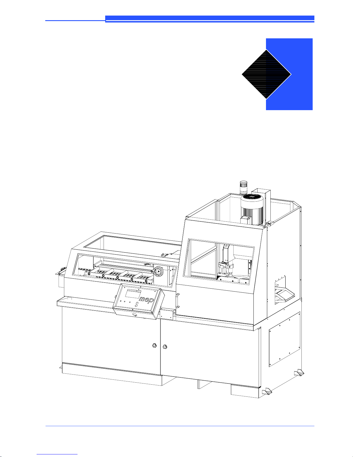
TIGER 370 CNC--MR
EN
Page 2

Page 3

EN
”CE” CONFORMITY DECLARATION
(according to EEC MACHINES DIRECTIVE 2006/42/CE annex II A)
The manufacturer:
SPA
SEGATRICI
Via Enzo Magnani, 1
61045 Pergola (PU) ITALIA
Tel. 072173721--Fax 0721734533
Hereby declares that the circular sawing machine:
Machine model:
Serial number:
Year of manufacture:
TIGER 370 CNC--MR
is in specification with the following directives:
• DIRECTIVE EEC MACHINES DIRECTIVE 2006/42/CE
• DIRECTIVE 2006/95/CE ”LVD”
• DIRECTIVE 2004/108/CE ”EMC”
• D. Lgs. 17/2010
Responsible of a Technical File
(Walter Di Giovanni)
c/o MEP SPA
Via Enzo Magnani, 1
61045 -- Pergola -- PU -- ITALY
Pergola, lì
Managing Director
(William Giacometti)
Page 4

Page 5

5
Introduction and technical specifications 1--1..........
Foreword 1--1...................................
Machine presentation 1--1..........................
Machine specification 1--2.........................
Technical Data 1--2...............................
Technical Data 1--4...............................
Dimensions 1--4.................................
Functional parts 2--1..............................
TIGER 370 CNC--MR model 2--1...................
Cutting head 2--2.................................
Cutting vice 2--2.................................
Control Panel 2--3................................
Feeder 2--3......................................
Base 2--4.......................................
Safety and accident prevention 3--1..................
Use of the machine 3--1...........................
General recommendations 3--1......................
Recommendations to the operator 3--2................
Machine safety devices 3--4........................
Reference standards 3--4...........................
Protection against accidental contact with the blade 3--5..
Electrical equipment 3--5..........................
Emergency devices 3--5...........................
Noise level of the machine 3--6......................
Noise level measurement 3--6.......................
Noise level values 3--7............................
Vibration emission 3--7............................
Electromagnetic compatibility 3--7...................
Machine installation 4--1...........................
Packaging and storage 4--1.........................
Anchoring the machine 4--4........................
Minimum requirements 4--4........................
Check list 4--4...................................
Connection to the compressed air supply 4--6..........
Connection to the power supply 4--6.................
Description of machine operation 5--1................
Description of the control panel 5--1.................
Page 6

6
Key for control console keyboard 5--1................
Basic instructions for carrying out a cutting cycle 5--4...
Manoeuvring the cutting head 5--4...................
Access to the cutting head 5--4......................
Manoeuvring the feeder 5--4........................
Clamping the work piece in the vice 5--4..............
Lubricant/coolant fluid supply 5--6...................
Preliminary check list for cutting operation 5--6........
Starting up the machine 5 --7........................
Semi--automatic operating cycle 5--8.................
Automatic operating cycle 5--12......................
Single program 5--15...............................
Multiple programming 5--22.........................
Multiple programming cuts 5--29.....................
Automatic loop operating cycle 5--30..................
Diagrams, exploded views and replace--
ment parts 6--1...................................
Pneumatic diagram TIGER 370 CNC--MR 6--1.........
Pneumatic diagram TIGER 370 CNC--FE HR 6--2......
APS/P drive for step motors 6--3....................
MEANING OF THE PARAMETERS IN THE TABLE 6--3
SCHEMATIC CONFIGURATION
OF INPUTS / OUTPUTS 6--7......................
LAYOUT OF APS/P DRIVE COMPONENTS 6--8.....
How to read the wiring diagrams 6--9.................
D2--Letter codes used to designate the type
of component 6--11................................
Standardised Wiring Diagrams TIGER 370 CNC--MR
(IEC 750 EN 60204--1 Standard) 6--14.................
List of cables 6--29................................
List of components 6--34............................
List of terminals 6--37..............................
List of IUD--IUV Card I nputs and Outputs 6--39.........
IUD: Digital Inputs and Outputs 6--39.................
IUV card: Miscellaneous Inputs and Outputs 6--39.......
CN 1 VICE 6--40..................................
CNSL card: Console Inputs and Outputs 6--41...........
Exploded views 6--42..............................
Page 7

7
Base 6--42.......................................
Fixed worktable 6--44..............................
Turntable 6--46...................................
Vice assembly 6--48...............................
Head unit 6--50...................................
Motor assembly 6-- 52..............................
Blade guard unit 6--54..............................
Electro--cylinder unit 6--56..........................
Supply carriage unit 6--58...........................
Supply roller unit 6--60.............................
Control panel 6--62................................
Guard rail 6--64...................................
Adjustments 7--1.................................
Displaying and editing the set--up parameters 7--1.......
Set language parameter 7--1........................
Set parameter for machine type 7--2..................
Set parameter for step motor 7--2....................
Setting blade characteristics, head downstroke
speed and bar initializing 7--5.......................
Blade motor and supply unit setting 7--5..............
Set minimum blade tension threshold 7--6.............
Optional settings 7--6.............................
Cutting head setting 7--7...........................
Head transducer calibration Set--up 7--7...............
Electronic systems 7--9............................
Replacing the microchip C8 on the control console 7--9..
Machine parameters Eeprom memory 7--9.............
Replacing the MEP 24 controller Eprom 7--10..........
Adjusting the display br ightness 7--11.................
Mechanical systems 7--12...........................
Cutting head stroke 7-- 12...........................
Adjusting the position of the blade--cleaning brush 7--12..
Replacing tool 7--14...............................
Feeder 7--15......................................
Vice 7-- 17.......................................
Adjusting the vice play 7--17........................
Adjusting the anti--chip device 7--18..................
Maintenance and choice of consumables 8--1...........
Page 8

8
The role of the operator 8--1........................
Maintenance requirements 8--2......................
General maintenance 8--2..........................
Daily 8--2.......................................
Weekly 8--2.....................................
Monthly 8--3....................................
Maintenance of working parts 8--3...................
Transmission box 8--3.............................
Consumable materials 8--4.........................
Oils for transmission box 8--4.......................
Oils for lubrication/coolant liquid 8--4................
Oils for spray mist system (optional) 8--4..............
Cutting speed and choice of tools 9--1................
Cutting speed 9 --1................................
Basic version 9--1................................
Choice of blade 9--2..............................
Tooth pitch 9--2..................................
Types of swarf: 9--3...............................
Cutting and feeding speed 9--3......................
Lubricant/coolant 9--4.............................
Blade structure 9--4...............................
Types of blades 9--5..............................
Tooth shape 9--5.................................
Blade selection table with respect to cutting speed and
downstroke speed 9--8.............................
Classification of steels 9--9.........................
Classification of steels 9--10.........................
Troubleshooting 10--1..............................
Troubleshooting blade and cutting problems 10--1........
Troubleshooting (control console diagnostics) 10--3......
Displaying the diagnostics menu 10--3.................
Diagnostics 10--4..................................
Error messages, alarm and emergency 10--7............
Optional 11--1....................................
Accessories available on request 11--1.................
Chute type bar loader CB 6001 11--1..................
Optional 11--3....................................
Blade 11--3......................................
Page 9

9
Roller table 11--3..................................
Can of emulsible oil 11--3...........................
Adattatore pianale a rulli lato scarico 11--3.............
Feed side roller table support 11--4....................
Motor chip discharger unit 11--4......................
Page 10

Page 11

1--1
Introduction and
technical
specifications
Foreword
We have decades of experience in the construction of the best metal ---cutting
machines. Our experience, our knowledge of our customers and constant
technological development of design and production equipment allow us to offer
a specific solution for every type of cutting need. This work tool has been
designed as a simple and reliable answer to the wide range of cutting needs of the
modern workshop. TIGER 370 CNC--- MR is rugged, quiet and safe. It cuts
various kinds of material, with very little scrap and great applicative flexibility
for
cutting copper, brass and bronze.
Congratulations for having chosen this product which, by following the instructions contained in this user and maintenance handbook, will guarantee you years
of dependable service.
This band saw has been exclusively designed to cut metals.
Machine presentation
TIGER 370 CNC---MR is an electromechanical pneumatic saw, which cuts metal
profiles and solids. It can operate in SEMIAUTOMATIC or AUTOMATIC
mode. In Semiautomatic mode, after setting the cutting head stroke and the head
downstroke speed on the control panel, position the vice 2÷3 mm from the
material being processed and press the start button on the control panel to
activate the disk (or foot pedal if supplied);
1.Thecuttervicecloses
2. The head lowers until the cut is made
(FCTA)
3. The head returns to
start position (FCTI)
4. The cutter vice
opens
In Automatic mode, after setting the cutting head stroke and the head downstroke speed on the control panel, position the vice 2÷3 mm from the material being
processed and press the start button on the control panel to activate the disk (or
foot pedal if supplied):
Warning
1
Page 12

MEP S.p.A.
1--2
2
Use and maintenance manual TIGER 370 CNC --MR
1.Thecuttervicecloses 2. The head lowers until the cut is made
(FCTA)
3. The head returns to
start position (FCTI)
4. The feed vice closes
5.Thecutterviceopens 6. The cutting material
is fed
7. The cuttingvice closes 8. The feed vice opens
and the cutting cycle
starts up
Machine specification
Theanodisedaluminiumnameplateisrivetedonthesideofthemachine;the
same data are reproduced on the declaration of conformity included with this use
and maintenance manual.
TIGER 370 CNC--FE MR
When communicating with the Technical Service department, the model, serial
number and year of manufacture of the machine must be quoted.
Tech n ical Data
WORKING PRESSURE
Max. working pressure for opening/closing vice Bar 6
Air consumption for a complete cycle Nl/min 5,74
The “air consumption” value refers to standard conditions (temperature 0° and
pressure 1.013 bar, i.e. density 1.3 x 10
-- 3
Kg/l) where 1 Kg/min. = 772 Nl/min.
N.B.
N.B.
Page 13

1--3
3
Introduction and technical specifications
LUBRICANT/COOLANT FLUID AND OIL
Lubricant/coolant fluid (oil concentration 5--- 6%) capacità Lt. 105
Oil for transmission box capacità Lt. 10
VICE
Vice max. opening mm 190
CUTTING CAPABILITY
Model Blade diameter
0° 370 120 100 180 x 100
45° ' 370 70 70 70 x 100
45° a 370 70 70 70 x 100
60° a 370 50 50 50 x 100
CUTTING CAPABILITY
Model Blade diameter
0° 370 120 100 180 x 100
45° ' 370 115 100 120 x 100
45° a 370 115 100 120 x 100
60° a 370 115 90 90 x 100
PACKED WEIGH T
Wooden cage and pallet Kg 250
Wooden pallet Kg 100
2600
1800
2100
Page 14

MEP S.p.A.
1--4
4
Use and maintenance manual TIGER 370 CNC --MR
Tech n ical Data
CUTTING SPEEDS
Speed rpm 900
Speed (optional) rpm 600900
Disk blade (HSS type)
External disc diameter mm 370
Internal hole diameter mm 32
Blade thickness mm 3
RATED ELECTRICAL POWER
Head spindle motor Kw 3
Electric coolant pump motor Kw 0,09 x 2
Feed step motor Kw 0,44
Step head motor kW 0,048
Max installed power kW 3.668
SPINDLE MOTOR
No.of poles Current (Volts) Absorption (Amps) Power (Kw) rpm
6 380 8,4 3 940---1130
Stator wound with enamelled copper wire, class H 200° C.
Class F insulation (limit temperature TL 155° C).
IP 54 protection rating (total against contact with live parts, water sprayed from all directions, with shaft oil
seal).
Conforming to CEI norms, publication: IEC 34 of 01/07/1985.
Dimensions
MACHINE INSTALLED
Work tabl e hei g ht mm 1000
Weight Kg 1060
Page 15

1--5
5
Introduction and technical specifications
Page 16
2--1
Functional parts
TIGER 370 CNC--MR model
In order for the user to move towards a full understanding of how the machine
works, which is described in detail in the chapter 5, this chapter deals with the
main units and their locations.
2
Page 17

MEP S.p.A.
2--2
7
Use and maintenance manual TIGER 370 CNC --MR
Cutting head
The cutter head makes the cut. It is contained inside guards preventing accidental
contact with the tool and moving parts. It is moved by an electro--- mechanical
cylinder (step motor), and runs on a twin linear guide with ball---bushing sliding
blocks. This system makes the structure highly rigid, providing a better cutting
finish with less vibration and noise.
Cutting vice
The vice is the unit that clamps the workpiece during cutting; it consists of a vice
support, commonly known as a “lead nut” fixed to the work table on which a
mobile jaw is mounted. The vice is operated manually by a handwheel and locked
by a Pneumatic cylinder.
Page 18
2--3
8
Functional parts
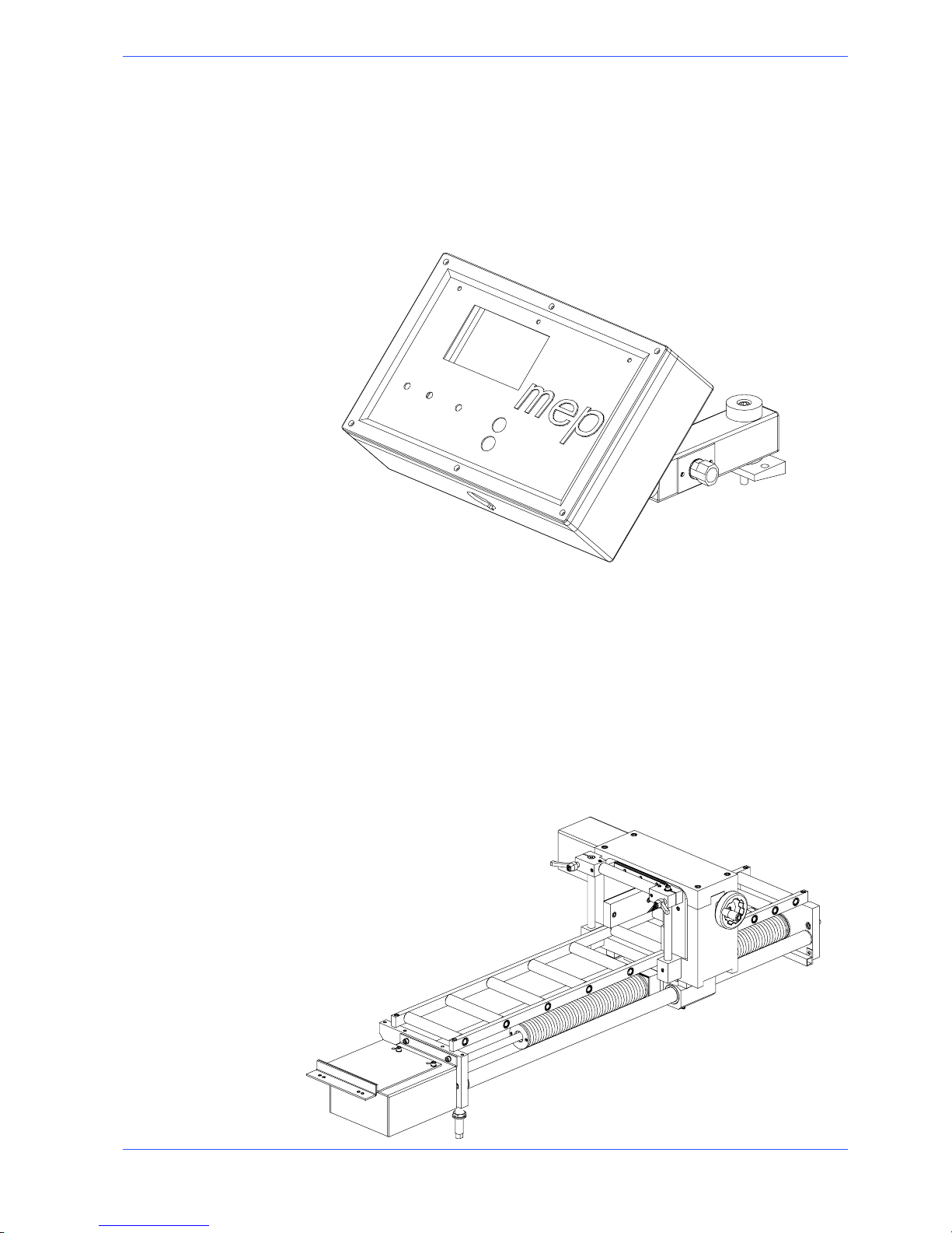
Control Panel
The control panel has a protection rating of IP 54 and contains the electronic
equipment. Access to the control panel is protected by a safety panel mounted on
hinges and fastened with screws, specially designed to prevent tampering. The
control panel swivels on two articulated joints so that it can be positioned by the
operator for greater ease---of---use and safety.
Feeder
The material, locked by means of the pneumatic vice, is delivered by a carriage
which conveys it along ground guides. The numeric check controls, with great
precision, the step motor of the infeed carriage, enabling the operator to set, on
the same bar, 32 batches of pieces to be cut, each with different amounts and
lengths.The material, locked by means of the pneumatic vice, is delivered by a
carriage which conveys it along ground guides. The numeric check controls, with
great precision, the step motor of the infeed carriage, enabling the operator to
set, on the same bar, 32 batches of pieces to be cut, each with different amounts
and lengths.
Page 19
MEP S.p.A.
2--4
9
Use and maintenance manual TIGER 370 CNC --MR
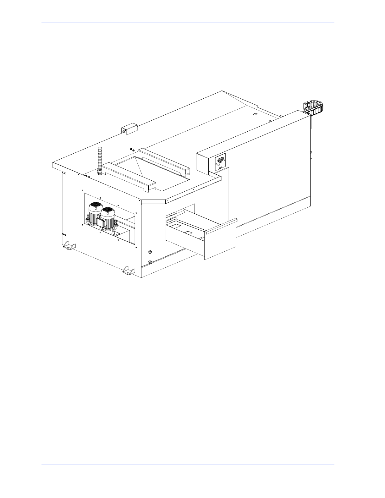
Base
This unit features a large coolant collection surface which conveys the coolant to
the rear tank via the tank cover, and a swarf collection drawer. An electric pump
is housed inside the tank which draws the clean fluid from the filter system.
Page 20

3--1
Safety and accident
prevention
The TIGER 370 CNC---MR has been designed and produced in accordance with
European standards. For the correct use of the machine we recommend that the
instructions contained in this chapter are carefully followed.
Use of the machine
The TIGER 370 CNC---MR circular saw is designed to cut exclusively non---fer-
rous profiles and solid metal sections. Other types of material and machining are
not compatible with the specific characteristics of the saw. The employer is
responsible for instructing the personnel who, in turn, are obliged to inform the
operator of any accident risks, safety devices, noise emission and accident
prevention regulations provided for by international standards and national laws
regardingtheuseofthemachine.Theoperatormustbeperfectlyawareofthe
position and function of all the machine’s controls.The instructions, warnings and
accident prevention standards in this manual must be respected without question
by all those concerned.The following definitions are those provided for by EEC
MACHINES DIRECTIVE 2006/42/CE :
H “Danger zone”: any zone in and/or around a machine in which the presence of a
person constitutes a risk for the safety and health of that person.
H “Person exposed”: any person finding himself either completely or partly in a
danger zone.
H “Operator”: the person or persons given t he responsibility of installing, operating,
adjusting, maintaining, cleaning, repairing or transporting the machine.
The manufacturer declines any responsibility whatsoever, either civil or criminal, should there be unauthorised interference or replacement of one or more
parts or assemblies on the machine, or if accessories, tools and consumable
materials are used that are different from those recommended by the manufacturer itself or if the machine is employed in a plant system and its proper
function is thereby altered.
General recommendations
LIGHTING
Insufficient lighting for the types of operation envisaged could constitute a safety
hazard for the persons concerned. For this reason, the machine user must provide
lighting in the working area sufficient to eliminate all shadowy areas while also
avoiding any blinding light concentrations. (Reference standard ISO 8995--- 89
”Lighting in work environments”).
CONNECTIONS
Check that the power supply cables and pneumatic feed systems comply with the
maximum machine absorption values listed in the “Machine Specification” tables;
replace if necessary.
Attention
3
Page 21
MEP S.p.A.
3--2
11
Use and maintenance manual TIGER 370 CNC --MR
EARTHING
The installation of the earthing system must comply with the requirements set out
in IEC STANDARD 204.
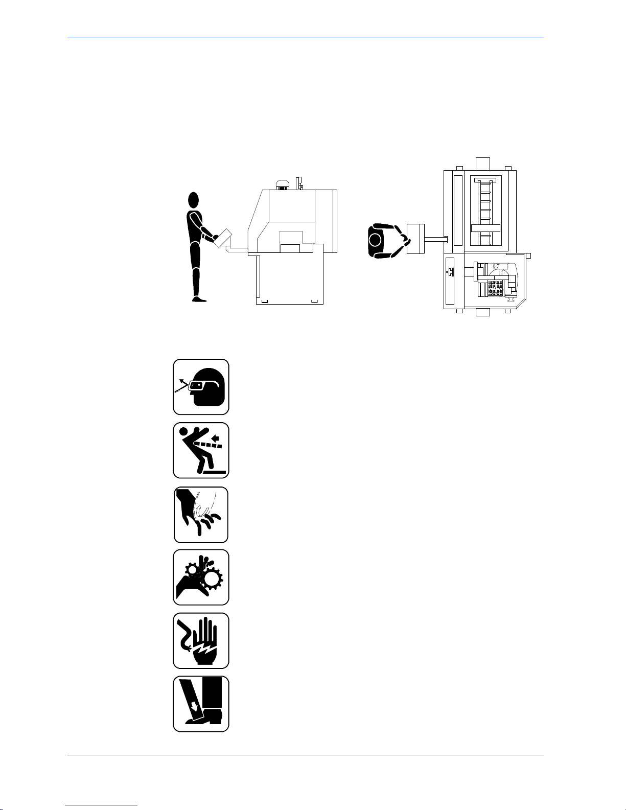
OPERATOR POSITION
The position of the operator controlling machine operations must be as shown in
the diagram below.
Recommendations to the operator
Always wear proper goggles or protective glasses.
Do not use the machine without the guards in position. Replace the polycarbonate windows , if subject to corrosion.
Do not allow hands or arms to encroach on the cutting zone while the
machine is in operation.
Do not wear oversize clothing with long sleeves, oversize gloves, bracelets, necklaces or any other object that may become entangled in the machine during working; long hair must be tied back and bunched.
Alwaysdisconnectthepowersupplytothemachinebeforecarryingout
any maintenance work whatsoever, including in the case of abnormal
operation of the machine.
Before starting cutting operations, support the material at both e nds of
the machine using the support arm --- standard, or OPTIONAL accessories such as the feed and discharge roller tables shown in the diagram
below.
Page 22
3--3
12
Safety and accident prevention
mm. 1500 mm. 1500
FEED ROLLER TABLE
DISCHARGE ROLLER TA-
BLE
Any maintenance work on the hydraulic or pneumatic systems must be
carried out only after the pressure in the system has been released.
The operator MUST NOT perform any risky operations or those not
required for the machining in course (e.g. remove swarf or metal shavings
form the machine while cutting).
Remove equipment, tools or any other objects from the cutting zone; always keep the working area as clean as possible.
Do not use the machine for cutting pieces which exceed the cutting capacity described in the technical specifications or are less than 5 mm
Before starting any cutting operations, ensure that the workpiece is securely held in the vice and the machine has been set correctly. A number
of examples of how to clamp the different profiles correctly in our machines are shown below.
Never move the machine while it is cutting.
Do not use blades of different sizes to those recommended in the machine’s specifications.
When cutting very short pieces, make sure that they are not dragged behind the support shoulder, where they could jam in the blade.
Page 23

MEP S.p.A.
3--4
13
Use and maintenance manual TIGER 370 CNC --MR
When using the pneumatic vice (version MA) check that the jaws actually
move right up to and effectively block the piece, as the maximum travel
in only 6 mm, and check that the clamping pressure is correct.
When working on the bandsa w, only wear gloves when handling materials
and tool change or adjustment operations. Only carry out one operation
at a time and do not hold more t han one ite m or operate more than one
device simultaneously. Keep hands as clean as possible.
Warning: if the blade jams in the cut, press the emergency stop pushbutton immediately. If this does not free t he blade, slowly release the vice,
remove the piece and check that the blade or its teeth for damage, if
need be replace the blade.
Before carrying out any repair works on the machine, consult the MEP
Technical Service; this can also be done through an agency in the country
in which the machine is being used.
Machine safety devices
This use and maintenance manual is not intended as purely a guide for the use of
the machine in a strictly productive environment, it is instead an instrument
providing information on how to use the machine correctly and safely. The
following standards are those specified by the EEC Committee in the directives
regarding safety of machinery, health and safety at work, personal protection and
safeguarding of the environment. These standards have been applied to the
TIGER 370 CNC---MR band saw.
Reference standards
MACHINE SAFETY
H EEC MACHINES DIRECTIVE 2006/42/CE ;
H EEC directive no. 2004/108/CE “EMC -- Electromagnetic Compatibility”;
H EEC Directive No. 2006/95/CE known as “Low voltage directive”.
HEALTH AND SAFETY AT WORK
H EEC Directive No. 80/1107; 83/477;86/188;88/188; 88/642 for the protection of
workers against risks caused by exposure t o physical, chemical and biological agents during working;
H EEC Directive No. 89/391 and Special EEC Directives No. 89/654 and No. 89/655
for improvements in health and safety at work;
H EEC Directive No. 90/394 for the protection of workers against risks deriving from
exposure at work to carcinogenic substances;
H EEC Directive No. 77/576 and No. 79/640 on safety signs at work.
PERSONAL PROTECTION
H EEC Directive No. 89/656 and No. 89/686 on the use of personal protection de-
vices.
ENVIRONMENTAL PROTECTION
H EEC Directive No. 75/442 on waste disposal.
H EEC Directive No. 75/439 on the disposal of used oil.
Page 24

3--5
14
Safety and accident prevention
Protection against accidental contact with the blad e
1. Metal disc cover fixed to the cutting head;
2. mobile protection of the disc attached to the guard, in order to guarantee
cover of the blade and to leave only the part of the disc used for cutting free
as required by President’s Decree 547/55 article 108;
3. vice with double ---blocking anti ---burr device to securely grip the workpiece;
4. the cutting and infeed vice is controlled by pneumatic devices, with maximum
6 mm stroke; the jaw which clamps the piece must be aligned to the part to be
processed at a distance of 2÷3 mm;
5. Access to the cutting zone is bounded by a door fitted with a timed lock,
which allows it to be opened only 5 or 10 seconds after the processing cycle
has stopped;
6. the cutting material supply is protected by a sheet ---metal casing, which can be
opened, that is fitted with a Perspex window to check the cutting operations.
1
6
2
5
3
4
Electrical eq u ip ment
In accordance with Italian standard CEI 60204---1, April 1998, derived from
European Standard EN 60204 ---1 publication IEC 204 ---1, 1997:
H 24 Vac Control voltage for actuators, in accordance with chapter 6 of European
Standard “Control and indication circuits” paragraph 2 “Control Circuits” sub-- section 1 “Preferential voltage values for control circuits”;
H plant protected against short circuits by quick blowing fuses and earthing of all
work and accidental contact parts;
H Protection from accidental start--up by a minimum voltage relay in the case of
power failure.
Emergency devices
In accordance with Standard CEI 204---1:
H Chapter 5 Section 6 Sub--section 1 ”Emergency stop device”: “the emergency
stop device immediately stops all t he dangerous and other functions of the machine”.
H Chapter 6 Section 2 Subsection 4 point 7 “Safety guards”: “the removal of
safety guards protecting dangerous parts or zones of the machine causes the machine to shut down immediately. When the guards are returned to their original
position the machine must be reset in order to resume work”.
...Emergency devices applicable to the TIGER 370 CNC ---MR:
1. Emergency stop: a non--- return mushroom---head pushbutton, colour red on
yellow background, is located on the control panel of the machine. To release
the pushbutton, the actuator must be rotated 45° . After the emergency situation has been resolved, the machine must be reset.
Page 25
MEP S.p.A.
3--6
15
Use and maintenance manual TIGER 370 CNC --MR
2. Thermal--- magnetic circuit breaker: this device incorporates two power fail-
ure protection systems. In fact, in the event of a power failure, it disconnects
all the electrical components, causing the machine to shut down immediately
and prevents it from automatically starting up again when power is restored.
The device also resets the thermal relay fitted to protect against current overloads.
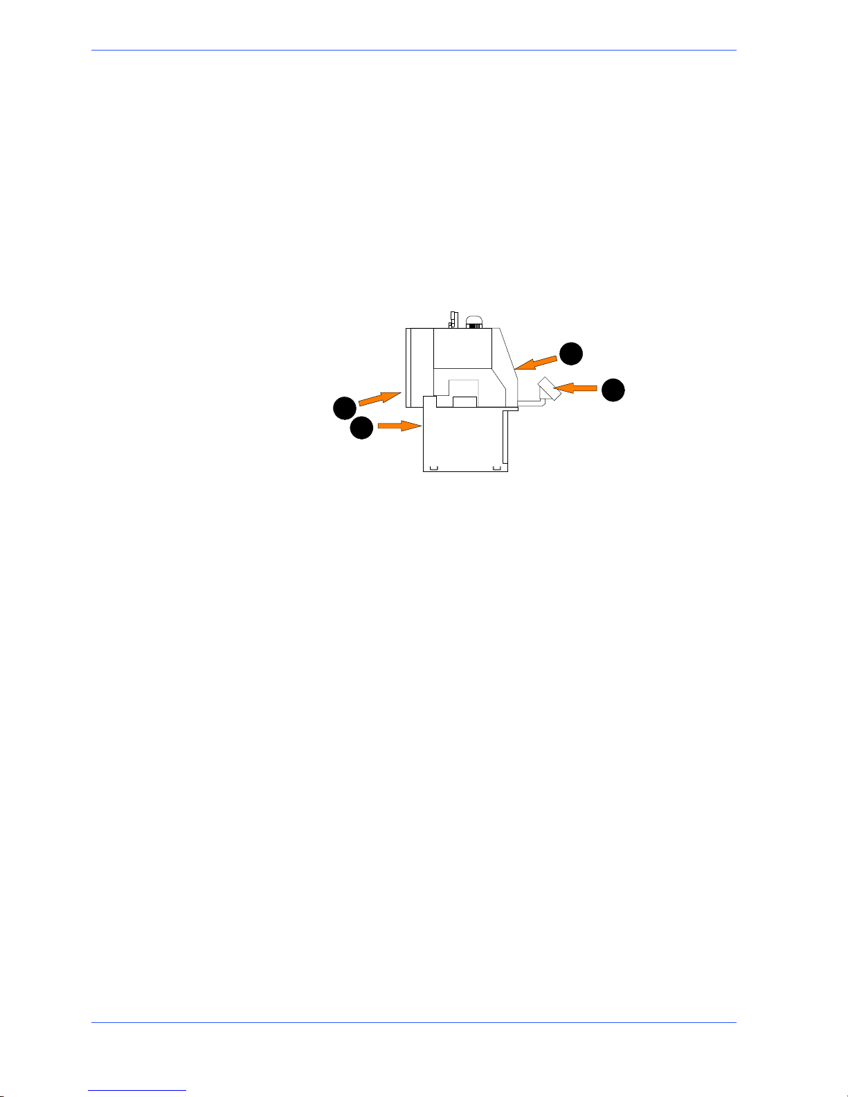
3. Head casing safety switch: to access the cutting zone it is necessary to open
the front door, pressing the relevant button on the control console. This device cannot be removed and has timed opening; therefore, it can only be
opened 5 or 10 seconds after the processing cycle has stopped.
4. Feeder casing safety switch: to access the cutting material feeder, it is necess-
ary to open the casing, with a safety limit switch that stops all machine operations that must be reset to continue processing.
2
3
1
4
Noise level of the machine
Noise can cause hearing damage and represents one the problems faced by many
countries who adopt their own standards. In accordance with the EEC MA-
CHINES DIRECTIVE 2006/42/CE , we are listing the standards that specify noise
levels for machine tools. This chapter also reports the noise levels produced by
the TIGER 370 CNC---MR during its various operating phases and the methods
used for measuring these levels. The Italian standard governing this aspect is
D.M.n.277/91 drawn from EEC Directives 80/1107, 82/605, 83/477, 86/188, 88/642,
UNI EN ISO 4871 (1998).
Noise level measurement
Noise levels are measured using an instrument known as an Integrator noise--meter which registers the equivalent continuous acoustic pressure level at the
work station. The damage caused by noise depends on three parameters: level,
frequency and duration. The equivalent level concept Leq combines the three
parameters and supplies just one indication. The Leq is based on the principle of
equal energy, and represents the continuous stationary level containing the same
amount of energy, expressed in dBA, as that actually fluctuating over the same
period of time. This calculation is made automatically by the integrator noise --meter. The measurements are taken every 60 seconds, in order to obtain a
stabilised value. The reading stays on the display for a sufficient time to enable a
reading to be taken by the operator.Measurements are taken by holding the
instrument at approximately 1 metre from the machine at a height of 1.60 metres
above the platform at the operator’s work s tation. Two measurements are taken:
the first while the machine operates without cutting anything, the second while
cutting in manual mode.
Page 26

3--7
16
Safety and accident prevention
Noise level values
Identification
Machine type
Circular sawing machine
Model
TIGER 370 CNC--- MR
Reference standard ISO 3746
Results
Te st 1st
Results
Mean sound level (Leq) 67,7 dB (A)
Environmental correction (K) 0,6 dB(A)
Peak sound power (Lw) 85,0 dB(A)
Test 2nd Results
Mean sound level (Leq) 65,2 dB(A)
Environmental correction (K) 0,6 dB(A)
Peak sound power (Lw) 82,6 dB(A)
Test 3rd Results
Mean sound level (Leq) 68,8 dB(A)
Environmental correction (K) 0,6 dB(A)
Peak sound power (Lw) 86,2 dB(A)
Vibration emission
This sawing machine complies with the norms EN1299 and EN1033, as the
machine vibration emission on the devices controlled by the operator does not
exceed the threshold of 2.5 m/s
2
Electromagnetic compatibility
As from 1 January 1996 all electrical and electronic appliances bearing the CE
marking that are sold on the European market must conform to Directive
2004/108/CE e 2006/95/CE and 2006/42/C
EE. The prescriptions regard two
specific aspects in particular:
1. “EMISSIONS: during its operation, the appliance or system must not emit spurious
electromagnetic signals of such magnitude as to contaminate the surrounding
electromagnetic environment beyond clearly prescribed limits”;
2. “IMMUNITY: the appliance or system must be able to operate correctly even when
it is placed in an electromagnetic environment that is contaminated by disturbances
of defined magnitude”.
The following text contains a list of the applied standards and the results of the
electromagnetic compatibility testing of machine model TIGER 370 CNC ---MR;
Test report no. 120101.
Emissions
H CEI EN 61000--6--4 (2002) Electromagnetic Compatibility (EMC) -- Generic stan-
dard regarding emissions. Part 6--4: Industrial Environment.
H EN 55011 (1999) Industrial, scientific, and medical radio frequency appliances
(ISM). Characteristics of radio frequency disturbance -- Limits and methods of
measurement.
H EN 55014--1 (2002) Electromagnetic Compatibility -- Prescriptions for domestic
appliances, electric power tools, and similar equipment. Part 1: Standard Emission
in relation to product family.
Page 27

MEP S.p.A.
3--8
17
Use and maintenance manual TIGER 370 CNC --MR
CONDUCTED EMISSIONS
Gate A Freq. ( MHz) Q --- p e a k l i m i t ( d B u V ) Mean value limit (dBuV) Result
A.C. power supply
input
0.15 --- 0.5
0 . 5 --- 5
5 --- 3 0
79 --- 73
(linear reduction with
log of frequency)
73
73
66 --- 60
(linear reduction with log of fre-
quency)
60
60
Complies
CONDUCTED EMISSIONS --- ANALYSIS OF INTERMITTENT DISTURBANCES
Gate Result
A.C. power supply input Not applicable
IRRADIATED EMISSIONS
Gate Freq. ( MHz) Q--- peak limit (10 m)
(dBuV/m)
Result
Enclosure 30 --- 230
230 --- 1000
40
47
Complies
Immunity
H CEI EN 61000--6--2 (2000) Electromagnetic Compatibility (EMC) -- Generic stan-
dard on immunity. Part 6 --2: Industrial Environment.
H EN 61000--4--2 + A1 (1996--1999) Electromagnetic Compatibility (EMC) -- Part 4:
Test and measurement techniques -- Section 2: Electrostatic discharge immunity
tests -- Basic publication.
H EN 61000--4--3 Electromagnetic Compatibility (EMC) -- Part 4: Test and measure-
ment techniques -- Section 3: Radiated, radio-- frequency, electromagnetic field immunity test.
H EN 61000--4--4 (1996) Electromagnetic Compatibility (EMC) -- Part 4: Test and
measurement techniques -- Section 4: Fast transients/bursts immunity tests -- Basic
publication.
H EN 61000--4--5 (1997) Electromagnetic Compatibility (EMC) -- Part 4: Test and
measurement techniques -- Section 5: Surge immunity test.
H EN 61000--4--6 (1995) Electromagnetic Compatibility (EMC) -- Part 4: Test and
measurement techniques -- Section 6: Immunity to conducted interference, induced
by radio frequency fields.
H EN 61000--4--11 (1977) Electromagnetic Compatibility (EMC) -- Part 4: Test and
measurement techniques -- Section 11: Voltage dips, short interruptions and voltage
variations immunity tests.
IMMUNITY TO ELECTROSTATIC DISCHARGES
Gate T est levels Evaluation criterion Result
Enclosure contact 4 kV
steel plate 4 kV
in air 8 kV
B Complies
IMMUNITY TO VOLTAGE (BURSTS)
Gate T est levels Evaluation criterion Result
A.C. power supply in-
put
2kV B Complies
IMMUNITY TO CONDUCTED ELECTROMAGNETIC FIELDS
Gate T est levels Evaluation criterion Result
A.C. power supply in-
put
10V A Complies
IMMUNITY TO IRRADIATED ELECTROMAGNETIC FIELDS
Gate T est levels Evaluation criterion Result
Enclosure 10 V/m A Complies
Page 28

4--1
Machine installation
Packaging and storage
MEP S.p.A. use packing materials that guarantee the integrity and protection of
the machine during its transport to the customer.
The type of packing differs according to the size, weight and destination.
Therefore the customer will receive the machine in one of two following ways:
1. on a pallet with straps and heat---shrink plastic;
2. on a pallet with straps, heat--- shrink plastic and a wooden crate.
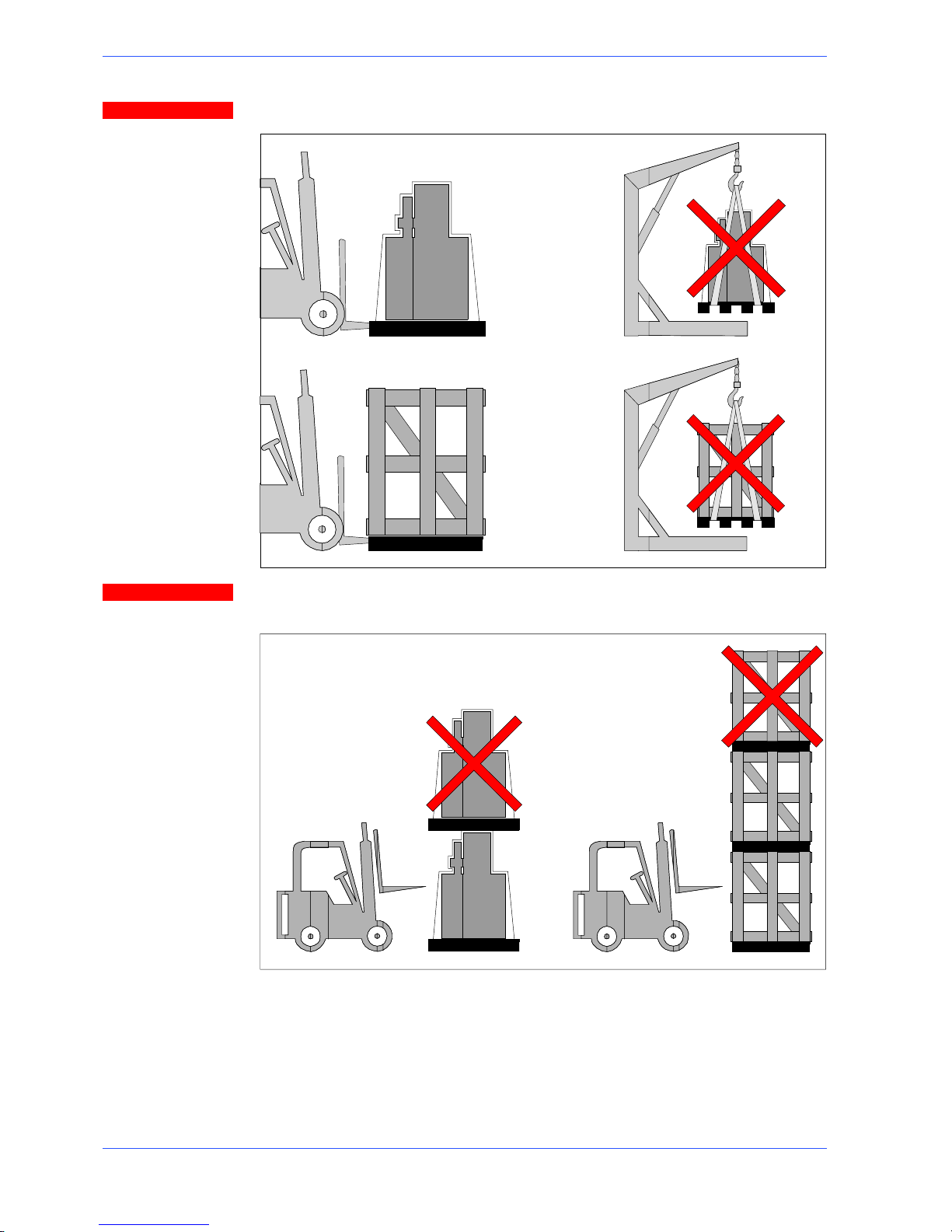
In both cases, for correct balancing the machine must be handled using a
fork-- lift truck, inserting the tines at the points indicated by the arrows, using
the reference marks on the crate itself.
Before carrying out lifting operations, make sure that the weight of the machine, as indicated on the crating or other packaging, is within the forklift truck
load limit.
Warning
Attention
4
Page 29
MEP S.p.A.
4--2
19
Use and maintenance manual TIGER 370 CNC --MR
Do not handle the packed machine using slings.
When storing, machines palletized and shrink--wrapped must not be stacked
two high, and machines pallettized and crated must not be stacked three high.
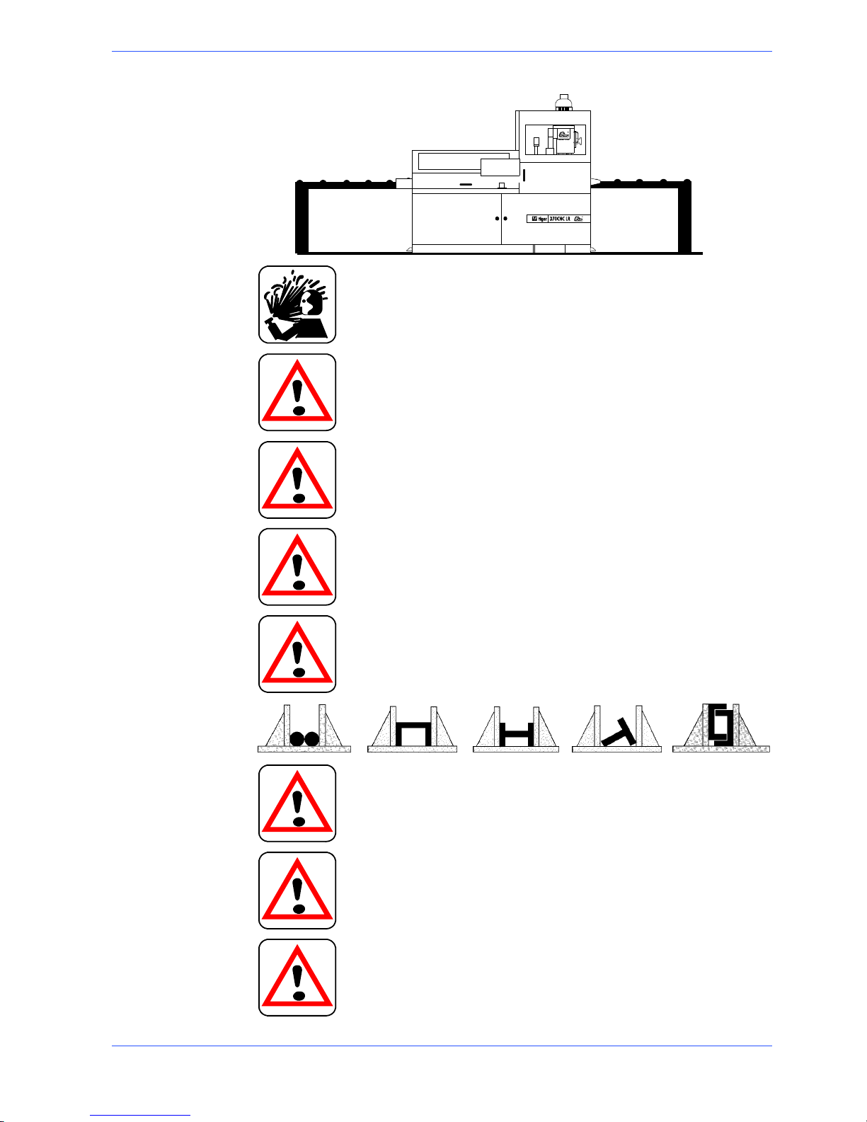
To install the machine, first remove the packing, paying particular attention not to
cut any electric wires or hydraulic hoses; if necessary use pliers, a hammer and a
cutter.
Open crate in the illustrated order:
Attention
Attention
Page 30

4--3
20
Machine installation
1. remove nails and lift the top of the cage;
2. remove nails and lower walls;
2
2
2
2
1
3. remove heat--- shrink covering;
4. remove the straps;
5. remove nails from pallet securing planks and remove planks;
6. remove the front panel and insert fork tines.
3
4
5
6
To locate the machine in the workplace, the machine dimensions and necessary
operator working space, including the spaces laid down in safety standards, must
be taken into account.
Page 31

MEP S.p.A.
4--4
21
Use and maintenance manual TIGER 370 CNC --MR
Anchoring the machine
The base of the machine is anchored to the floor by two permanent studs located
on the sides of the base. The studs are screwed into nuts previously sunk into the
concrete, and tightened from above with lock nuts. The schematic specifications
set out in Chapter 1 should be taken into account when positioning the machine.
2226
747,5
Minimum requirements
For the machine to function correctly, the room in which it is to be installed must
satisfy the following requirements:
H power supply voltage/frequency: refer to the values on the rating plate;
H working pressure not less than 6 Bar and not greater than 8 Bar;
H temperature of machine location: from --10 to +50° C;
H relative humidity: not more than 90%;
H lighting: not less than 500 Lux.
The machine is already protected against voltage variations, but will only run
trouble--free if the variations do not exceed ± 10%.
Check list
Before starting installation, check that all the accessories, whether standard or
optional, supplied with the machine are present. The basic version of the TIGER
370 CNC ---MR is supplied complete with:
CHARACTERISTICS
Multi --- microprocessor with two controlled axes that permits programming 32
batches of workpieces with different lengths and quantities on the same bar
n
Three--- stage drive system to ensure a high level of rigidity and precision, and to
attain a great capacity for removal
n
Warning
Page 32

4--5
22
Machine installation
CHARACTERISTICS
Fully encased model to provide operator safety, sound insulation and the possibility
of working with large quantities of liquid
n
HSSdiskø370x32x3forsteel n
HM disk ø 400 x 32 x 3.6 for aluminium and light alloys n
Cabinet for electric and electronic equipment with fully identifiable wiring, door---
locking switch with padlockable device, emergency device, motor overload cut --- out,
minimum voltage coil and protection against a missing phase
n
Activation and control systems protected by input and output electric and electronic devices
n
Low tension control panel: softkey polyester keypad with thermo---moulded touch
sensitive buttons and acoustic signal when the machine is started
n
48 character x 16 li ne display showing technical parameters such as: number of cuts
programmed and executed, blade thickness, single forward movement measure,
cutting time, ammeter, display of diagnostic messages (approx. 80) and warnings in
the language chosen
n
Four controls to program the cutting head stroke limits, according to the dimensions of the bars to be cut
n
Programming and control console with LCD display comprehensive of self--- diagnosis messages
n
Blade rotation with motor at a speed, together with an electronic variable speed
drive, making cutting possible from 15 to 150 rpm to always accomplish the best
efficiency
n
Spray gun to wash the work surfaces n
Pneumatic clamp with adjustable steel gib n
Acoustic and flashing light signal in case of machine stop n
Infeed unit with step motor; screw/nut with ball bushing (length 1000 mm) n
Vice with rag prevention device and double workpiece clamping feature n
Swing feeder vice to deliver even deformed bars n
Coolant tank obtained in the pedestal with a pair of motor pumps for a total deliv-
ery of 120 l/min
n
Chip drawer n
Electric pump to lubricate and cool the disk n
Blade cleaning brush n
Upright pneumatic vice for cutting more than one bar n
Cutting head moving on twin linear guide with pre--- loaded double ball--- bushing
sliding blocks
n
Head movement with electro--- mechanical cylinder to provide the greatest cutting
rigidity
n
Rotating pin with pre--- loaded thrust bearing to ensure precision and reliability n
Machine set for handling with pallet truck n
Keys, user manual and manual for ordering spare parts in the language used n
Motor chip discharger n
Roller platform adapter on loading and unloading side n
Emulsifiable oil 5 l n
MEP slide bar loader for high production (CB6001)* n
*ACCESSORIES AVAILABLE ON REQUEST
Accessory kit is placed before the packaging inside the machine; it contains the
following items:
H 3, 4, 5, 6, 8 and 10 mm Allen keys;
H open 19 mm wrench;
Page 33

MEP S.p.A.
4--6
23
Use and maintenance manual TIGER 370 CNC --MR
H this Use and Maintenance Manual.
Connection to the compressed air supply
To ensure perfect operation and a long service life, it is recommended that the
machine is connected to a compressed air system having the characteristics
reported in the diagram below.
1
2
3
4
5
6
KEY
1 - DOWN PIPE
2 - CONDENSATE COLLECTOR
3 - DRAIN COCK
4 - AIR FILTER
5 - DRAIN COCK
6 - CONNECTING HOSE
Connection to the power supply
Before connecting the machine to the power supply, check that the socket is not
connected in series with other machines. This requirement is fundamental for the
good operation of the machine.To connect the machine to the power supply,
proceed as follows:
" connect the power supply cable of the machine to a plug which matches the
socket to be used. (EN 60204---1; par. 5.3.2).
CONNECTION FOR ”5-CORE” WIRE SYSTEMS WITH NEUTRAL
R=L1
S=L2
T=L3
PE = GND
N = NEUTRAL
CONNECTION FOR ”4-CO
R
E” WIRE SYSTEMS WITH NEUTRAL
S=L2
T=L3
PE = GND
R=L1
When using systems with a neutral wire, special care must be taken when connecting the blue neutral wire, in that if it is connected to a phase wire it will discharge the phase voltage to the equipment connected for voltage: phase--
neutral.
Attention
Page 34

4--7
24
Machine installation
" Insert the plug in the socket, ensuring that the mains voltage is the same as
that for which the machine has been setup.
VOLT ?VOLT ?
" To switch on the machine, turn the main switch located at the rear, on the
right---hand side of the electric cabinet;
" press the ON button on the control console;
" press RESET twice.
The above sequence (ON and RESET buttons) must be performed each time the
machine is switched on.
Make sure that the disk rotates properly. To do this, proceed as follows:
" make sure the machine is not in emergency status (red mushroom head but-
ton released); otherwise, release the emergency stop button and press
RESET;
" set the cutting head downstroke adjuster by means of the specific selector;
" set the speed of the disc by means of the relevant potentiometer;
Page 35

MEP S.p.A.
4--8
25
Use and maintenance manual TIGER 370 CNC --MR
" enable motor rotation by activating the blade motor selector on the control
console;
" start disc rotation using the start pushbutton on the control panel or the pedal
control (if machine is equipped);
" if all the above operations have been carried out correctly, the disc motor will
start up and the disc will start to turn.
Ensure that the blade moves in the correct direction as shown in the
above figure. If it does not, simply reverse two of the phase wires on the ma-
chine’s power supply input.
The sawing machine is now ready to start the work for which it was designed.
Chapter 5 provides a detailed description of the various functions of the machine
and its operating cycles.
Attention
Page 36

5--1
Description of
machine operation
This chapter analyses all the machine functions. We begin with a description of
the pushbuttons and other components on the control panel.
Description of the control panel
The control console is housed inside the control panel in an IP 54 rated housing
which is tamperproof and resistant to dust and moisture. The control panel
swivels on two articulated joints so that it can be positioned by the operator for
greater ease of use and safety. The figure below shows the control panel of
TIGER 370 CNC---MR:
Key for control console keyboard
On key: enables machine operation Cutting vice closure
5
Page 37

MEP S.p.A.
5--2
27
Use and maintenance manual TIGER 370 CNC --MR
Cutting vice opening
RESET key: resets the machine after an
emergency condition or conflicting commands.
Blade motor selector: during normal
operation of the machine, this enables or
disables the cutting cycle start button
(START)
Start button: starts the cutting cycle
STOP button: stops the machine in the
automatic cycle only
Speed de--- selection key (zero)
Head lowering speed potentiometer Cutting force control potentiometer
Disk rotation speed potentiometer
Function key:
In automatic work mode, allows you to enter
programming and return to execution
In programming work mode, allows you to
switch between the program cuts and select
program displays
Function Key:
Calling up program No.
Scrollimg the cursor
Storing data
Storing programs
Selecting programs
Storing parameters
Function Key:
In automatic work mode, allows you to delete
the last program carried out by loading the new
one to be carried out
In programming work mode, allows you to delete existing or incorrect data
When entering cutting or machine parameters,
allows you to delete existing or incorrect data
Manual movement of feed carriage foreward
Manual movement of feed carriage
backward
Head up key Head down key
Main vice closure Main vice opening
EMERGENCY mushroom: pressing this
button all the operations of the machine
stop immediately. To reset the emergen-
cy, rotate the actuator by 45
°
Gun sprays lubricant/coolant fluid even
when the machine is stopped
Page 38

5--3
28
Description of machine operation
Jet of lubricant/coolant fluid from taps,
only when the cycle has started
No lubricant/coolant fluid jet
Button for memorizing the FCTI (Head
Upstroke Limit)
Button for memorizing the FCTA (Head
Downstroke Limit)
Button to open and close the timed door
of the cutting head
Chip discharger unit in manual mode
Chip discharger unit deactivated Chip discharger unit in automatic mode
Decimal point for entering numerical
values in tenths of a millimetre or thousandths of an inch when programming
parameters and cutting lenghts.
Selecting operating mode
F0: Function Key:
Takes you from single to multiple programming in automatic work mode
F1: function key
At machine start up, it allows programming the setup parameters.
F2: Function key not operational
F3: Function Key:
Selects semi---automatic work mode in
the main menu
F4: Function Key:
Selects Automatic work mode in the
Main menu
F5: Function Key:
Resets total cutting time counter in
semi--- automatic work mode
F6: Function Key:
Selects diagnostic work mode in the
main menu
zeroing command
Enables step=length check in automatic
work mode
F7: function key
in automatic mode it enables the selection of the single cycle i.e. the basket
change cycle, or the continuous cycle
F8: Function Key:
--- Allows operator to enter blade thick-
ness value in automatic work mode
F9: Function Key:
Takes you from the first display to the
zero--- setting display
Takes you from the zero---setting display
to the main menu
Takes you back to the main menu
Page 39

MEP S.p.A.
5--4
29
Use and maintenance manual TIGER 370 CNC --MR
Basic instructions for carrying out a cutting cycle
Manoeuvring the cutting head
In the TIGER 370 CNC---MR model, it is possible to move the cutting head with
up and down buttons, shown in the key of the control panel in this chapter.
Head up key Y+ Head down key Y --
Access to the cutting head
To ensure operator safety, the machine is entirely enclosed by safety guards that
prevent accidental contact with the tool and moving parts. To access the cutting
zone it is necessary to unlock the device closing the door.
Button to open/close the door of the cutting head
Manoeuvring the feeder
The power supplier can be moved with the buttons reported on the diagram
below, only after having reset the power supply (as explained in the “machine
start up” paragraph).
Forward key X+ Back key X--
Clamping the work piece in the vice
Vice opening and closure, for the cutting vice and the feeder vice, are controlled
by the corresponding buttons on the control console.
Cutting Vice close button Cutting vice open button
Feeder vice close button Feeder vice open button
Page 40

5--5
30
Description of machine operation
However, to ensure that the workpiece is securely clamped in the vice, proceed as
follows:
" make sure the workpiece dimensions do not exceed the machine’s cutting ca-
pacity;
" make sure the piece is correctly supported on both sides of the machine;
" move the vice to within 2÷3 mm of the workpiece using the handwheel. Press
the vice closure button on the console;
2--3 mm
" make sure that the material is well blocked by trying to move it manually, as
thevicecylinderhasastrokeof6mmonly.
Page 41

MEP S.p.A.
5--6
31
Use and maintenance manual TIGER 370 CNC --MR
Lubricant/coolant fluid supply
It is possible to select the operating mode of the coolant by means of the specific
buttons on the control panel:
Technological control parameters
The following table indicates the control parameters which are shown on the
displays of the semi ---automatic, automatic and Automatic Loop operating cycles.
X =1000,5
X--- axis dimension (position of feeder carriage)
θ =00,00
Nonoperating
W =000.0
Nonoperating
F=0
Cutting head descent speed potentiometer
S=15
Disc rotation speed (rpm)
Kg=000
Nonoperating
DL=0
Nonoperating
SL= 3
Blade thickness (depends upon machine model)
AM=5,8
Max. blade motor absorption
A =0,7
Amperometer
T =00,00
Partial cutting time
TT=00,00
Total machine time for the cutting cycle
Preliminary check list for cutting operation
To guarantee complete safety during cutting cycles, the operator should work
through a check list of the entire apparatus, checking:
" ensure that the disk guard completely surrounds the tool when it is not in use;
" that the work piece is properly clamped in place;
" ensure that the blade teeth are appropriate for the material being cut;
" that the speed selected is right for the kind of piece to be cut;
" that all protections are in place and correctly locked;
" lubricant/coolant level and activation of the electropump;
" the blade downstroke speed must be correct.
Page 42

5--7
32
Starting up the machine
When switching on the machine, proceed as follows:
" press the ON button.
" Press RESET twice.
The display shows the introductory and starting SCREEN.
" To c o n ti n u e p r e s s F 9 .
" The display suggests ZERO SETTING the machine. To carry out this opera-
tion,pressF6. Togotothemainmenu,pressF9.
During zero setting, the display will read ZERO SETTING IN PROGRESS,
which will continue to be displayed until the operation has been completed. While
zero setting is taking place, only the EMERGENCY button is active.
" When ZERO SETTING has been completed, the display will show the
COUNT STARTING VALUE for the X axis. Press F9 to continue.
Page 43

MEP S.p.A.
5--8
33
Use and maintenance manual TIGER 370 CNC --MR
Semi--automatic operating cycle
" Starting from the main menu, press F3 to put the machine in SEMI ---AUTO-
MATIC mode.
MAIN MENU
F3 = SEMI-AUTOMATIC
F4 = AUTOMATIC
F5 = AUTOMATIC-LOOP
F6 = DIAGNOSTICS
F9 = ZERO SETTING MENU
" The display will show the screen for the SEMI ---AUTOMATIC cycle.
SEMI-AUTOMATIC
X=
θ° =
W=
F = 153
S=
kg= 10
DL= 0
SL= 3
AM= 0.0
A = 0.1
T= 0:0
TT= 0:10
CURRENT CYCLE
F9 = MAIN MENU
F5 = RESET TT
Technological control parameters
X =1000,5
Nonoperating
θ =00,00
Nonoperating
W =000.0
Nonoperating
F=0
Cutting head descent speed potentiometer
S=15
Disc rotation speed (rpm)
Kg=000
Nonoperating
DL=0
Nonoperating
SL= 3
Blade thickness
AM=5,8
Assorbimento motore
A =0,7
Amperometer
T =00,00
Partial cutting time
TT=00,00
Total machine time for the cutting cycle
Clamping the work piece in the vice
" Release the protection by pressing the relevant key;
Page 44

5--9
34
" open the vice by rotating the handwheel anti ---clockwise and position the
workpiece between the jaws.
" Bring the moveable jaw to within 2÷3 mm of the workpiece by rotating the
handwheel clockwise.
2 --- 3 m m
" Block the piece by means of the pneumatic cutting vice block, by pressing the
close cutting vice button.
" Check that the workpiece is effectively locked in positon!
If the vice was already closed by the pneumatic piston, it may not block the
piece. In this case it is necessary to repeat the operation, i.e.: open the vice by
pressing the specific button, bring the moving jaw near to the piece and block
it again with the closing button, bearing in mind that the stroke of the pneumatic piston is approx. 6 mm.
Cutting stroke adjustment
" Once the workpiece is locked in position, the cutting stroke must be adjusted.
When the head down button is pressed, the cutting head is automatically lowered.
N.B.
Page 45

MEP S.p.A.
5--1035Use and maintenance manual TIGER 370 CNC --MR
" Keep the button pressed until the disk is at 5/10 mm from the material to be
cut.
" Memorize the FCTI (Head Upstroke Limit) by pressing the specific button;
" after pressing the FCTA memorizing button, the display will indicate that it
has been memorized.
SEMI-AUTOMATIC
X=
θ° =
W=
F = 153
S=
kg= 10
DL= 0
SL= 3
AM= 0.0
A = 0.1
T= 0:0
TT= 0:10
CURRENT CYCLE
F9 = MAIN MENU
F5 = RESET TT
FCTI
" The FCTI (Head Downstroke Limit) will be restored at the end of the cut.
Preparing to cut
" Select the fluid for automatic operation by pressing the specific button. The
led of the relative button will light up.
" Adjust the head descent speed potentiometer to 0 to avoid undesirable start-
ing speeds.
Cutting
" Close the protection and press the reset button;
" Enable motor rotation by activating the blade motor selector on the control
console;
Page 46

5--11
36
" start operation.
At this stage it is possible to adjust, according to the type of material, the 2
parameters which influence the cut: the disk rotation speed and the head
downstroke speed, through the relative potentiometers on the control panel.
Now the blade starts, the cutting cylinder is under pressure and the lubricant/
coolant supply starts.
In this phase, pressing the head dowstroke button, the FCTA spot is deleted.
" When the machine arrives at the end of the cut it is necessary to memorize
the FCTA position, by pressing the relative button;
" when the machine reaches the position to start cutting again, the symbol to
indicate the FCTA upstroke limit will re ---appear on the display.
SEMI-AUTOMATIC
CURRENT CYCLE
FCTA
" At the same time, the disk will stop and the cutting head will return to the
start of cut position (FCTI).
" When the head arrives at the start of cut position, the display will indicate the
FCTI position.
SEMI-AUTOMATIC
X=
θ° =
W=
F = 153
S=
kg= 10
DL= 0
SL= 3
AM= 0.0
A = 0.1
T= 0:0
TT= 0:10
CURRENT CYCLE
F9 = MAIN MENU
F5 = RESET TT
FCTI
" Next, the machine automatically opens the cutting vice.
The machine is ready to carry out a new cutting cycle.
N.B.
N.B.
Page 47

MEP S.p.A.
5--1237Use and maintenance manual TIGER 370 CNC --MR
Automatic operating cycle
" Return to the main menu to change the operating mode. To return to the
MAIN MENU press F9.
MAIN MENU
F3 = SEMI-AUTOMATIC
F4 = AUTOMATIC
F5 = AUTOMATIC-LOOP
F6 = DIAGNOSTICS
F9 = ZERO SETTING MENU
" Now press the F4 button to go to the AUTOMATIC cutting cycle.
" The AUTOMATIC screen shows the parameters inserted for the last opera-
tion completed.
AUTOMATIC
X=
θ° =
W=
F = 153
S=
kg= 10
DL= 0
SL= 3
AM= 0.0
A = 0.1
T= 0:0
TT= 0:10
F0 = PGR. SINGLE
F9 = MAIN MENU
F8 = BLADE THICKNESS
F7 = SING/CONT CYCLE
F6 = EXEC. STEP/CONT
CUTS
EXEC.
θ CUTS
PROG.
SINGLE CYCLE
RUN/PROG=PROGRAMMING
PGR. NO MEASUR. CUTS PROG.
10 512,8 2343
OPERATING CYCLE
PROGRAMME DATA
PGR. NO. = When the AUTOMATIC cycle screen switches on, the programme
number for the last programme memorised is displayed, irrespective of whether it was
totally or partially completed or only saved. The control memory allows 32 programmes to be memorised as well as the single programme. The latter programme is
indicated by the number 0.
MEASUREMENT = As for the situation described above, the MEASUREMENT
value displayed also relates to the last programme memorised. The control memory
allows cutting lengths of up to 9999,9 mm. to be memorised. The cutting length can be
programmed to an accuracy of a tenth of a millimeter. PRECISION ±0.1 mm. 0÷1000
mm (Precision as regards the position of the feeding car and not to the cut part)
CUTS PROG. = In the case of the number of CUTS PROGRAMMED, the same information as above appli es. It is possible to set a maximum number of cuts of 9999
pieces for each programme.
CUTS EXEC. = The number of CUTS EXECUTED displayed relates to those effectively completed before the machine was last switched off. These will remain in the
memory until they are replaced by further cuts carried out using the same programme,
or until they are zero set or modified by a new programme.
OPERATING BUT-
TONS ACTIVE DUR-
ING THE AUTOMATIC
CYCLE
F0 = SINGLE PROGRAMME: Press this button to access the single programme.
Using this option, programming can be done directly on the work screen. The single
programme allows 1 MEASUREMENT and 1 QUANTITY of cuts to be carried out.
This possibilty has been included to avoid multiple programming procedures when
these are not necessary.
Page 48

5--13
38
OPERATING BUT-
TONS ACTIVE DUR-
ING THE AUTOMATIC
CYCLE
F9 = MAIN MENU: press this button to return to the working mode selection menu.
F8 = BLADE THICKNESS: this option gives access to programming of the BLADE
THICKNESS. This parameter is very important because the bar infeed system operates in zero setting mode, therefore the value of the scrap produced by the disk must
be added to the size of the piece to be processed. Adding and subsequent division by
the number of runs necessary to obtain the required measurement, will be carried out
independently on the control console.
F7 = SING/CONT CYCLE: this operation is more easily understood if the SINGLE
CYCLE is called the CHANGE TOTE --- BOX cycle. In practice, when a number of
measurements and pieces are programmed for the same bar, this option allows them
to be kept separate, stopping the machine at the end of each programme.
Inserting and locking the workpiece
Initially the machine could be configured in any way, therefore the first series of
operations to be carried out is to set the machine for the material to be cut.
" Bring the cutting head to the upstroke limit, using the manual head lift but-
ton;
" Release the protection by pressing the relevant key;
" open the cutting vice and the infeed vice by rotating the relative handwheels;
then adjust the position of the anti---chip vice indicated by the arrow.
" After this second operation, check that the pneumatic piston is in open posi-
tion. To do this, use the supply vice and cutting vice opening buttons.
It is advisable to use the buttons a number of times, to be totally familiar with
operation.
Page 49

MEP S.p.A.
5--1439Use and maintenance manual TIGER 370 CNC --MR
" The second series of operations are to fit the material to be cut: place the ma-
terial between the vice jaws, and draw one end under the blade in order to
perform an initial cut to initialize the cuts.
" After inserting the material, bring the moving jaws for the cutting and feeder
vices to within 2
÷3 mm of the workpiece;
" activate the automatic pneumatic vices to block the piece, using the two vice
closing buttons;
" check that the piece is well blocked;
to avoid deformation when the tubes are thin walled, or the blocking force of the
vices is not sufficient for materials which are particularly hard or with articulated
sections, adjust the vice pressure by means of the regulator located inside the
base.
Preparing to cut
" Close the protection and press the reset button;
" adjust the cutting stroke by memorizing the head upstroke limit (FCTI): bring
the cutting head near the material using the head downstroke button.
" Memorize the cutting start position by pressing the FCTI (Head Upstroke
Limit) button. The FCTI indication will appear at the top of the display on
the right hand side.
AUTOMATIC
X=
θ° =
W=
F = 153
S=
kg= 10
DL= 0
SL= 3
AM= 0.0
A = 0.1
T= 0:0
TT= 0:10
F0 = PGR. SINGLE
F9 = MAIN MENU
F8 = BLADE THICKNESS
F7 = SING/CONT CYCLE
F6 = EXEC. STEP/CONT
CUTS
EXEC.
θ CUTS
PROG.
SINGLE CYCLE
RUN/PROG=PROGRAMMING
PGR. NO MEASUR. CUTS PROG.
10 512,8 2343
OPERATING CYCLE
FCTI
Programming cuts
Once the material to be cut has been inserted and blocked, bring the cutting head
to the FCTI (Head Upstroke Limit) position, set the cutting dimension indicated
Page 50

5--15
40
on the display as Measure, and the amount of pieces to be cut Prog. cuts.
AUTOMATIC
X=
θ° =
W=
F = 153
S=
kg= 10
DL= 0
SL= 3
AM= 0.0
A = 0.1
T= 0:0
TT= 0:10
F0 = PGR. SINGLE
F9 = MAIN MENU
F8 = BLADE THICKNESS
F7 = SING/CONT CYCLE
F6 = EXEC. STEP/CONT
CUTS
EXEC.
θ CUTS
PROG.
SINGLE CYCLE
RUN/PROG=PROGRAMMING
PGR. NO MEASUR. CUTS PROG.
10 512,8 2343
OPERATING CYCLE
FCTI
For the cutting program it is necessary to set the following parameters:
H PGR. N. = PROGRAM NUMBER: this value identifies all existing programs, the-
refore it is possible to select a program previously memorized by setting a number,
or the number proposed by the controller can be accepted.
H MEASUREMENT = MEASUREMENT OF PIECES: This value is keyed in, using
the numeric keys, in mm and tenths of a mm, or in inches and thousandths of an
inch, relates to the selected programme.
H PROGRAMMED CUTS = NUMBER OF PIECES TO BE CUT PER MEASURE:
set this value using the numeric keys in relation to the PGR. N. and MEASURE
set.
The machine’s control console allows cuts to be programmed in two ways:
H SINGLE PROGRAMME: This option enables programming on the work screen,
setting the measurements and number of pieces to be obtained from the workpiece.
H MULTIPLE PROGRAMMING: With this programming system 32 cutting lengths
can be set with relative number of pieces to be cut for each dimension. Furthermore, selecting the programs, it is possible to set cutting sequences with different
measures on the same bar.
Single program
" To set the measure and number of pieces in the single program, press F0.
F0 = PGR. SINGLE
F9 = MAIN MENU
F8 = BLADE THICKNESS
F7 = SING/CONT CYCLE
F6 = EXEC. STEP/CONT
MEASUR.
AUTOMATIC
OPERATING CYCLE
X=
θ° =
W=
F = 153
S=
kg= 10
DL= 0
SL= 3
AM= 0.0
A = 0.1
T= 0:0
TT= 0:10
CUTS
EXEC.
θ CUTS
PROG.
SINGLE PROGRAM
RUN/PROG=PROGRAMMING
PGR. NO CUTS PROG.
0 512,8 2343
FCTI
" When the F0 button has been pressed, the display reads:
PGR. NO. 0
MEASUREMENT The last measurement programmed
CUTS PROG. The last number of cuts programmed
CUTS EXEC. The portion of the last job executed. The type of pro-
Page 51

MEP S.p.A.
5--1641Use and maintenance manual TIGER 370 CNC --MR
gramme in use will appear in the first square: SINGLE PGR. To begin programming, press RUN/PROG.
F0 = PGR. SINGLE
F9 = MAIN MENU
F8 = BLADE THICKNESS
F7 = SING/CONT CYCLE
F6 = EXEC. STEP/CONT
MEASUR.
AUTOMATIC
OPERATING CYCLE
X=
θ° =
W=
F = 153
S=
kg= 10
DL= 0
SL= 3
AM= 0.0
A = 0.1
T= 0:0
TT= 0:10
CUTS
EXEC.
θ CUTS
PROG.
SINGLE PROGRAM
RUN/PROG=PROGRAMMING
PGR. NO CUTS PROG.
0 512,8 2343
FCTI
" When the RUN/PROG button has been pressed, the measurements will be
reversed, indicating that they can be changed. To set new measurements, key
in using the NUMERIC KEYS. Enter the measurement 905,7 (for example).
To do so the following keys must be pressed: “9” “0” “5” “.” “7”
F0 = PGR. SINGLE
F9 = MAIN MENU
F8 = BLADE THICKNESS
F7 = SING/CONT CYCLE
F6 = EXEC. STEP/CONT
MEASUR.
AUTOMATIC
OPERATING CYCLE
X=
θ° =
W=
F = 153
S=
kg= 10
DL= 0
SL= 3
AM= 0.0
A = 0.1
T= 0:0
TT= 0:10
CUTS
EXEC.
θ CUTS
PROG.
SINGLE PROGRAM
RUN/PROG=PROGRAMMING
PGR. NO CUTS PROG.
0 905,7 2343
FCTI
" Pressing the numeric keys, the numbers are displayed from right to left. If you
make a mistake when writing the measure, press CLEAR to delete the value;
0.0. will appear. After entering the measure, press ENTER. With this operation you will obtain two results:
1) the new value is memorized;
2) the reverse moves to PROG. CUTS to set the desired number of cuts.
F0 = PGR. SINGLE
F9 = MAIN MENU
F8 = BLADE THICKNESS
F7 = SING/CONT CYCLE
F6 = EXEC. STEP/CONT
MEASUR.
AUTOMATIC
OPERATING CYCLE
X=
θ° =
W=
F = 153
S=
kg= 10
DL= 0
SL= 3
AM= 0.0
A = 0.1
T= 0:0
TT= 0:10
CUTS
EXEC.
θ CUTS
PROG.
SINGLE PROGRAM
RUN/PROG=PROGRAMMING
PGR. NO CUTS PROG.
0 905,7 2343
FCTI
" With the reverse on PROG. CUTS, set the number of cuts to be executed
using the numeric keys as for the previous operation. Digit 100, pressing in
order buttons “1” “0” “0”; then press ENTER again. With this operation you
will obtain two results:
Page 52

5--17
42
1) the new value is memorized;
2) the reverse moves to NR PGR.
F0 = PGR. SINGLE
F9 = MAIN MENU
F8 = BLADE THICKNESS
F7 = SING/CONT CYCLE
F6 = EXEC. STEP/CONT
MEASUR.
AUTOMATIC
OPERATING CYCLE
X=
θ° =
W=
F = 153
S=
kg= 10
DL= 0
SL= 3
AM= 0.0
A = 0.1
T= 0:0
TT= 0:10
CUTS
EXEC.
θ CUTS
PROG.
SINGLE PROGRAM
RUN/PROG=PROGRAMMING
PGR. NO CUTS PROG.
0 905,7 2343
FCTI
" End of programming. Press RUN/PGR to return to execution.
Whenever CLEAR is pressed in the single program automatic mode, when the
machine is stopped, the count of the cuts executed previously is reset.
" After pressing RUN/PGR, the reverse will disappear from the display; this
indicates that the machine is ready for operation. To confirm the new program, press CLEAR; this will produce two results:
1) confirmation of the program to be executed
2) count reset of cuts executed previously.
F0 = PGR. SINGLE
F9 = MAIN MENU
F8 = BLADE THICKNESS
F7 = SING/CONT CYCLE
F6 = EXEC. STEP/CONT
MEASUR.
AUTOMATIC
OPERATING CYCLE
X=
θ° =
W=
F = 153
S=
kg= 10
DL= 0
SL= 3
AM= 0.0
A = 0.1
T= 0:0
TT= 0:10
CUTS
EXEC.
θ CUTS
PROG.
SINGLE PROGRAM
RUN/PROG=PROGRAMMING
PGR. NO CUTS PROG.
0 905,7 2343
FCTI
" Enter the value BLADE THICKNESS which must be programmed every ti-
me the tool is changed. It is necessary to add also the blade thisckness to the
cutting measure, because the bar supply system works when the carriage is at
zero, i.e. after being cut, the piece is on the right of the blade, and this value
is subtracted from the total length of the finished piece. Press F8 to enter this
value.
RUN/PROG = PREVIOUS MENU
BLADE THICKNESS = 3
RESIDUAL
PROGRAMMED = 1547 m
BLADE LIFE = 952 m
MAXIMUM BLADE MOTOR CURRENT
TORTOISE 1ST SPEED AMP. = 12.5
SPEED HEAD AP MPP = 1
BAR INITIALIZING SIZE = 170
N.B.
Page 53

MEP S.p.A.
5--1843Use and maintenance manual TIGER 370 CNC --MR
" After pressing F8 the display will show BLADE THICKNESS. To enter the
value press in order the numeric keys and the decimal point. To memorize the
new value press ENTER again. Of course, in case of a typing error, it is possible to correct it by pressing CLEAR. Once the operation is complete, press
RUN/PROG to return to the operating display screen.
F0 = PGR. SINGLE
F9 = MAIN MENU
F8 = BLADE THICKNESS
F7 = SING/CONT CYCLE
F6 = EXEC. STEP/CONT
MEASUR.
AUTOMATIC
OPERATING CYCLE
X=
θ° =
W=
F = 153
S=
kg= 10
DL= 0
SL= 3
AM= 0.0
A = 0.1
T= 0:0
TT= 0:10
CUTS
EXEC.
θ CUTS
PROG.
SINGLE PROGRAM
RUN/PROG=PROGRAMMING
PGR. NO CUTS PROG.
0 905,7 2343
FCTI
" Now it is possible to start operation. To check the measure of the piece cut,
press F6; in the first box the indication STEP will appear.
F0 = PGR. SINGLE
F9 = MAIN MENU
F8 = BLADE THICKNESS
F7 = SING/CONT CYCLE
F6 = EXEC. STEP/CONT
MEASUR.
AUTOMATIC
OPERATING CYCLE
X=
θ° =
W=
F = 153
S=
kg= 10
DL= 0
SL= 3
AM= 0.0
A = 0.1
T= 0:0
TT= 0:10
CUTS
EXEC.
θ CUTS
PROG.
SINGLE PROGRAM
RUN/PROG=PROGRAMMING
PGR. NO CUTS PROG.
0 905,7 2343
FCTI
" After pressing F6, the machine proceeds as follows:
--- S TA RT
--- INITIAL CUT
--- B A R S U P P LY
--- C U T I N A U T O M AT I C M O DE
--- S T OP.
Themachineperformsthefirstcycleofoperations,tocuttosizethefirstpiece. This enables a precise check of the measure of the piece. If the size is correct, press F6 again to deactivate the check cycle, then press START.
F0 = PGR. SINGLE
F9 = MAIN MENU
F8 = BLADE THICKNESS
F7 = SING/CONT CYCLE
F6 = EXEC. STEP/CONT
MEASUR.
AUTOMATIC
OPERATING CYCLE
X=
θ° =
W=
F = 153
S=
kg= 10
DL= 0
SL= 3
AM= 0.0
A = 0.1
T= 0:0
TT= 0:10
CUTS
EXEC.
θ CUTS
PROG.
SINGLE PROGRAM
RUN/PROG=PROGRAMMING
PGR. NO CUTS PROG.
0 905,7 2343
FCTI
Page 54

5--19
44
" If the size is not correct, use the BLADE THICKNESS parameter to enter
the correction value. Repeat the cut with the check cycle activated. In this case the machine will perform the following operations:
--- S TA RT
--- B A R S U P P LY
--- C U T I N A U T O M AT I C M O DE
--- S T OP.
In other words, the machine starts again where it had stopped, automatically
changing the size with the set adjustment, and supplying the bar with the new
measure. Check the size again, and if it is correct, press F6 to delete STEP,
then press START.
F0 = PGR. SINGLE
F9 = MAIN MENU
F8 = BLADE THICKNESS
F7 = SING/CONT CYCLE
F6 = EXEC. STEP/CONT
MEASUR.
AUTOMATIC
OPERATING CYCLE
X=
θ° =
W=
F = 153
S=
kg= 10
DL= 0
SL= 3
AM= 0.0
A = 0.1
T= 0:0
TT= 0:10
CUTS
EXEC.
θ CUTS
PROG.
SINGLE PROGRAM
RUN/PROG=PROGRAMMING
PGR. NO CUTS PROG.
0 905,7 2343
FCTI
" Select the cutting speed.
" Select the fluid for automatic operation by pressing the specific button. The
button led will light up.
" Set the head descent speed regulator to 0 to prevent inadvertent movement of
the cutting head, once the cycle starts.
Cutting
" Enable motor rotation by activating the blade motor selector on the control
console;
" start operation.
Now the blade starts, the cutting cylinder is under pressure and the lubricant/
coolant supply starts. At this stage it is possible to adjust, according to the type of
material, the 3 parameters which influence the cut: the disk rotation speed and
the head downstroke speed, through the relative potentiometers on the control
panel.
Page 55

MEP S.p.A.
5--2045Use and maintenance manual TIGER 370 CNC --MR
In this phase, pressing the head dowstroke button, the FCTA spot is deleted.
" When the machine arrives at the end of the cut it is necessary to memorize
the FCTA position, by pressing the relative button;
" once the FCTA memorising button has been pressed, the display will show the
symbol confirming memorisation.
F0 = PGR. SINGLE
F9 = MAIN MENU
F8 = BLADE THICKNESS
F7 = SING/CONT CYCLE
F6 = EXEC. STEP/CONT
MEASUR.
AUTOMATIC
OPERATING CYCLE
X=
θ° =
W=
F = 153
S=
kg= 10
DL= 0
SL= 3
AM= 0.0
A = 0.1
T= 0:0
TT= 0:10
CUTS
EXEC.
θ CUTS
PROG.
SINGLE PROGRAM
RUN/PROG=PROGRAMMING
PGR. NO CUTS PROG.
0 905,7 2343
FCTI
" Then the machine will bring the head to the FCTI spot, and will deliver the
material to execute another cut in the set mode: step or continuous.
Every time the machine finishes a cut the number of CUTS EXEC. is updated
by one unit. The initial cut, and the cuts executed after an emergency, are not
counted.
" Themachinecanstopintwoways,wheninautomaticmode:BARFIN-
ISHED or CUTS FINISHED in both cases, all that is required to exit these
situations is to press the RESET button, following which the machine will
again be ready to begin a new cutting programme, or cutting a new bar. In
both cases a clear message will be displayed.
CUT FINISHED
BAR FINISHED
PRESS RESET PRESS RESET
N.B.
N.B.
Page 56

5--21
46
" The cuts programmed in the SINGLE PGR. have finished. The display will
show the relative message;
CUT FINISHED
PRESS RESET
" the machine stops in position to start cutting.
" Pressing RESET the display return to the operating screen, displaying the da-
ta of the program in progress. Press CLEAR to reset the cuts previously done.
F0 = PGR. SINGLE
F9 = MAIN MENU
F8 = BLADE THICKNESS
F7 = SING/CONT CYCLE
F6 = EXEC. STEP/CONT
MEASUR.
AUTOMATIC
OPERATING CYCLE
X=
θ° =
W=
F = 153
S=
kg= 10
DL= 0
SL= 3
AM= 0.0
A = 0.1
T= 0:0
TT= 0:10
CUTS
EXEC.
θ CUTS
PROG.
SINGLE PROGRAM
RUN/PROG=PROGRAMMING
PGR. NO CUTS PROG.
0 905,7 2343
FCTI
Page 57

MEP S.p.A.
5--2247Use and maintenance manual TIGER 370 CNC --MR
Multiple programming
" Press button F0 to access the MULTIPLE PROGRAMMING. The display
proposes the data of the last program executed before switching off the machine, or before the SINGLE PGR.
" The first box will show the message referring to one of the two operating mo-
des of the automatic program:
1) CONTINUOUS CYCLE: sequence programs;
2) SINGLE CYCLE: one program at a time.
Press the RUN/PROG button to set operation and to enter the data.
AUTOMATIC
X=
θ° =
W=
F = 153
S=
kg= 10
DL= 0
SL= 3
AM= 0.0
A = 0.1
T= 0:0
TT= 0:10
F0 = PGR. SINGLE
F9 = MAIN MENU
F8 = BLADE THICKNESS
F7 = SING/CONT CYCLE
F6 = EXEC. STEP/CONT
CUTS
EXEC.
θ CUTS
PROG.
CONTINUOUS CYCLE
RUN/PROG=PROGRAMMING
PGR. NO MEASUR. CUTS PROG.
10 905,7 2343
OPERATING CYCLE
FCTI
" After pressing the RUN/PROG button, the display will show a programming
screen to program cuts and select the programs to be executed. The function
of each button is described in the message. To access CUT PROGRAMMING press F1.
PROGRAMMING
F1 = PROGRAMMING CUTS
F2 = SELECT PROGRAMMES
F3 = SEL. PROG. LOOP
" The first CUT PROGRAMMING display screen shows the program number
in reverse, which means that it is possible to change the value. Start entering
the operating parameters from program No. 1; to enter the program number
Page 58

5--23
48
press the numeric key1: the old value will automatically be replaced by the
new one.
PROGRAMMING CUTS
PROGRAMME Nº=
MEASUREMENT=
Nº OF CUTS =
θ° CUT =
WIDTH =
12
331
2002.2
0° 0’
0.0
" After pressing 1, press ENTER. With this operation you will obtain two re-
sults:
1) the desired program number is memorized;
2) the reverse moves to measure, which means that it is possible to change its
value.
PROGRAMMING CUTS
1
200.2
331
PROGRAMME Nº=
MEASUREMENT=
Nº OF CUTS =
θ° CUT =
WIDTH =
0° 0’
0.0
" With the reverse on MEASURE the value of the first batch of pieces to be cut
can be entered, i.e. L=178; to enter this value press the numeric keys in order. Any typing mistakes can be deleted by pressing CLEAR. After digiting
the numbers, press ENTER; the reverse will pass to CUTS No.
PROGRAMMING CUTS
1
331
178
PROGRAMME Nº=
MEASUREMENT=
Nº OF CUTS =
θ° CUT =
WIDTH =
0° 0’
0.0
" Repeat the same operation to set the number of cuts; press in order the nu-
meric keys 5 and 0. After digiting the numbers press ENTER. With this operation you will obtain two results:
1) the new value is memorized;
Page 59

MEP S.p.A.
5--2449Use and maintenance manual TIGER 370 CNC --MR
2) the display screen scrolls automatically to show the next program, i.e.
PGR. NUMBER 2.
PROGRAMMING CUTS
500
2
323.5
PROGRAMME Nº=
MEASUREMENT=
Nº OF CUTS =
θ° CUT =
WIDTH =
0° 0’
0.0
" At this point, the operator can chose whether to set operation in this program
(no.2), or to select PROGRAM POSITION number and enter new values, as
described previously. Proceed with setting the programs in order.
FIRST PROGRAMME
PROGRAMMING CUTS
50
178
1PROGRAMME Nº=
MEASUREMENT=
Nº OF CUTS =
θ° CUT =
WIDTH =
0° 0’
0.0
SECOND PROGRAMME
PROGRAMMING CUTS
112
60
2
PROGRAMME Nº=
MEASUREMENT=
Nº OF CUTS =
θ° CUT =
WIDTH =
0° 0’
0.0
Page 60

5--25
50
THIRD PROGRAMME
PROGRAMMING CUTS
120
15
3
PROGRAMME Nº=
MEASUREMENT=
Nº OF CUTS =
θ° CUT =
WIDTH =
0° 0’
0.0
" After setting all the cutting programs, press ENTER. The last value entered
will be memorized and the display will scroll to the next program.
PROGRAMMING CUTS
30
630
4
PROGRAMME Nº=
MEASUREMENT=
Nº OF CUTS =
θ° CUT =
WIDTH =
0° 0’
0.0
" Once the programs have been set, press the RUN/PROG button to quit Cut
Programming.
" After pressing the RUN/PROG button, the display will show the Program-
mingscreen.Nowtheprogramstobeexecutedmustbecommunicatedtothe
controller. To do this press F2.
PROGRAMMING
F1 = PROGRAMMING CUTS
F2 = PROGRAMME SELECTION
F3 = SEL. PROG. LOOP
" Set the sequence of programs to be executed, up to maximum 32. The display
screen shows the cursor in position A, and the last program numbers set in
order of execution. There is no limit in relation to the programmable order,
whether it be in i ncreasing, decreasing, repetitive or jump order, nor in relation to the minimum number of programs.
Page 61

MEP S.p.A.
5--2651Use and maintenance manual TIGER 370 CNC --MR
" Press the numeric keys to set the programs: digit 1 to set the 1st.
ABCDEFGH
11 12 16 17 18 20 23 21
IJKLMNOP
29 30
QRSTUVWZ
AA BB CC DD EE FF GG HH
" After pressing the numeric key the value is immediately updated. As usual, in
case of typing errors, it is possible to correct them by pressing CLEAR. After
setting the new program to be executed, press ENTER. The new value is memorized and the cursor moves to the next position.
ABCDEFGH
1 2 16 17 18 20 23 21
IJKLMNOP
29 30
QRSTUVWZ
AA BB CC DD EE FF GG HH
" Set the second program by pressing the numeric key 2, then press ENTER.
Proceed as described above for the remaining cutting programs to be executed.
ABCDEFGH
123 17 18 20 23 21
IJKLMNOP
29 30
QRSTUVWZ
AA BB CC DD EE FF GG HH
Page 62

5--27
52
" Select the third programme by pressing the numeric key: 3 and press:
ENTER. Repeat the operation to select the last cutting programme to execute.
ABCDEFGH
1234 18 20 23 21
IJKLMNOP
29 30
QRSTUVWZ
AA BB CC DD EE FF GG HH
" Once the last program has been set, complete the selecting operation by pres-
sing CLEAR.
" After pressing CLEAR, the previous value is deleted and 0 appears. To con-
firm the end of the programming operations and that only the first four programs are to be executed press ENTER again.
ABCDEFGH
12340 20 23 21
IJKLMNOP
29 30
QRSTUVWZ
AA BB CC DD EE FF GG HH
" At this point, all the other programs memorised are deleted, and the cursor
returns to the first position. Now it is possible to return to the operating diplay screen by pressing the RUN/PROG button.
ABCDEFGH
1 234
IJKLMNOP
QRSTUVWZ
AA BB CC DD EE FF GG HH
Page 63

MEP S.p.A.
5--2853Use and maintenance manual TIGER 370 CNC --MR
" Pressing the RUN/PROG button again, the PROGRAMMING display screen
returns.
PROGRAMMING
F1 = PROGRAMMING CUTS
F2 = PROGRAMME SELECTION
F3 = DEL. PROG. LOOP
" Pressing the RUN/PROG button, the operating display screen returns, where
no parameter has been changed yet. To activate the new program set, press
CLEAR. With this operation you will obtain two results:
1) the data of the previous program is deleted from the memory;
2) the data of the new program is entered.
" After pressing CLEAR, the display screen will show the data of the new pro-
gram being executed.
Whenever CLEAR is pressed in the automatic operation mode in the multiple
programming, with the machine stopped, the operation in progress is reset.
This means that if the machine has performed some cuts of the first program,
and it is stopped by pressing CLEAR, the cuts already executed are reset.
When the machine restarts it will start from the initial cut and therefore from the
first cut programmed. If the machine is stopped by pressing CLEAR during the
execution of a program after the first, for example the second or third, the display will return to the first program of the series programmed, resetting the
number of cuts executed in all the programs performed until that moment.
When the machine is restarted, the machine will start from the initial cut, i.e.
from the first cut of the first program.
The second operating mode in Multiple Programming is the Single Cycle.
" The message Single Cycle will replace Continuous Cycle by pressing F7.
AUTOMATIC
X=
θ° =
W=
F = 153
S=
kg= 10
DL= 0
SL= 3
AM= 0.0
A = 0.1
T= 0:0
TT= 0:10
F0 = PGR. SINGLE
F9 = MAIN MENU
F8 = BLADE THICKNESS
F7 = SING/CONT CYCLE
F6 = EXEC. STEP/CONT
CUTS
EXEC.
θ CUTS
PROG.
CONTINUOUS CYCLE
RUN/PROG=PROGRAMMING
PGR. NO MEASUR. CUTS PROG.
10 905,7 2343
OPERATING CYCLE
FCTI
Activating this option the machine will operate as follows: at the end of the cuts
in each program, the machine will stop and wait for a new START command. This
allows replacing the piece collection container, in order to separate pieces of
different sizes. To return to the Continuous cycle mode press F7.
N.B.
Page 64

5--29
54
Multiple programming cuts
Press the STA RT button to re---start the cutting cycle.
" When the START button has been pressed, the display reads AUTOMATIC
EXECUTION. In this mode, all manual commands are blocked. The commands available when the machine is cutting are: EMERGENCY --- RUN/
PROG --- STOP.
" Press STOP with the machine cutting;
STOP
F9 = OPERATING SCREEN
START = CONTINUES CYCLE
RESET = CYCLE START
" after pressing STOP the machine stops with the last operation in progress. In
other words, if the machine was cutting, it stops with the blade on the cut and
waits for the next instructions. This control is important for the use of the
machine: for example, when the machine is started without having set the program to be executed, or when the cut or supply are not correct, or whenever it
is necessary to momentarily stop the machine.
BEGIN CUT = Pressing RESET the display returns to the operating screen and the machine returns to the cutting start position. This is to correct the necessary parameters and restart the cycle.
CONTINUOUS CYCLE = If during the cut or material supply something falls into the machine,
a tool or cloth or something else, it is necessary to stop the machine by pressing STOP to draw it
out. Press START to activate the machine again.
WORK SCREEN = In case of doubts concerning the program in progress, after pressing STOP
and the machine is stopped, it is possible to return to the operating screen by pressing F9, leaving
the program in progress. After verifying the doubts, press F9 to return to the STOP screen and
decide whether to restart the cycle by pressing START or stop it by pressing RESET.
Page 65

MEP S.p.A.
5--3055Use and maintenance manual TIGER 370 CNC --MR
Automatic loop operating cycle
" Press F9 to pass to the main menu and change operating mode.
" Press F5 to pass to tha cutting cycle in AUTOMATIC LOOP. This mode ena-
bles the machine to execute cuts with different depths and lengths on the same bar.
MAIN MENU
F3 = SEMI-AUTOMATIC
F4 = AUTOMATIC
F5 = AUTOMATIC-LOOP
F6 = DIAGNOSTICS
F9 = ZERO SETTING
" Press F7 to select the LOOP mode, that can be single or continuous.
" SINGLE LOOP: this operating mode is used to cut material at preset depths
(P1, P2, P3) and lengths (L1, L2, L3), while the possibility of intervening in
the work cycle on completion of each LOOP executed, is retained.
AUTOMATIC LOOP
X=
θ° =
W=
F = 153
S=
kg= 10
DL= 0
SL= 3
AM= 0.0
A = 0.1
T= 0:0
TT= 0:10
F0 = PGR. SINGLE
F9 = MAIN MENU
F8 = BLADE THICKNESS
F7 = SING/CONT CYCLE
F6 = EXEC. STEP/CONT
CUTS
EXEC.
θ CUTS
PROG.
SINGLE LOOP
PGR. NO
MEASUR. CUTS PROG.
0 905.7 2343
OPERATING CYCLE
FCTI
" CONTIUOUS LOOP: this operating mode is used to obtain preset depths
and lengths of cuts on material, with LOOP repetitions up to 99 times.
AUTOMATIC LOOP
X=
θ° =
W=
F = 153
S=
kg= 10
DL= 0
SL= 3
AM= 0.0
A = 0.1
T= 0:0
TT= 0:10
F0 = PGR. SINGLE
F9 = MAIN MENU
F8 = BLADE THICKNESS
F7 = SING/CONT CYCLE
F6 = EXEC. STEP/CONT
CUTS
EXEC.
θ CUTS
PROG.
PGR. NO
MEASUR.
CUTS PROG.
0 905.7 2343
OPERATING CYCLE
FCTI
SINGLE LOOP
Page 66

5--31
56
L1 L2 L3 L4
P1
P2
P3
Ltot = L1 + L2 + L3 + L4
" Prepare for cutting as if for an automatic cycle (see the instructions in the
relevant paragraph).
" Set cutting parameters as indicated in the automatic cycle paragraph, for pro-
gramme data and technological machine control parameters.
" By pressing run/prog. programming is accessed. Press the F1 button, to pro-
gramme cuts.
" Key in the values for each field and confirm each piece of data input by press-
ing ENTER.
PROGRAMMING CUTS
1
100
1
PROGRAMME Nº=
MEASUREMENT=
Nº OF CUTS =
θ° CUT =
WIDTH =
0° 0’
45.5
" When ENTER is pressed again, the screen for the second LOOP programme
appears. Proceed to input the data for further programmes. When completed,
press RUN/PROG. Press the F3 key on the programming screen, which relates to LOOP PROGRAMME SELECTION.
PROGRAMMING CUTS
1
100
2
PROGRAMME Nº=
MEASUREMENT=
Nº OF CUTS =
θ° CUT =
WIDTH =
0° 0’
45.5
Page 67

MEP S.p.A.
5--3257Use and maintenance manual TIGER 370 CNC --MR
" All that remains to be done, is that the sequence of execution of cutting pro-
grammes is to be established. Key in the programme numbers, to correspond
to the letters, confirming each one by pressing ENTER.
ABCDEFGH
1 12 16 17 18 20 23 21
IJKLMNOP
29 30
QRSTUVWZ
AA BB CC DD EE FF GG HH
LOOP NR. = 99
" Also key in the number of LOOPS if using a continuous work cycle. Press
RUN/PROG. to proceed.
" The display screen will show the parameters of the first program set. Pressing
START the machine is reset and performs the initial cut before starting the
LOOP. Then the supply unit places the material of the length set in the first
program and the head descends to execute the cut. PROGRAMMING FCTA
will appear on the display. Once the cutting depth has been reached, reset the
head downstroke regulator by stopping the cutting head stroke; then press the
Head Downstroke Limit (FCTA) memorizing button.
" Memorise the cut depth for the second programme and so on for all pro-
grammes selected. On completion of this operation the user can select whether the cuts should be carried out in single or continuous mode, by pressing F7.
Page 68

6--1
Diagrams, exploded
views and replace-ment parts
This chapter contains functional diagrams and exploded views of the TIGER 370
C N C --- M R . This document is intended to help in identifying the location of the
various components making up the machine, giving information useful in carrying
out repair and maintenance operations; This chapter will also enable the user to
order replacement parts with no risk of misunderstanding, as all parts are given
codes.
Pneumatic diagram TIGER 370 CNC--MR
solo HR e MR
6
Page 69

MEP S.p.A.
6--2
59
Use and maintenance manual TIGER 370 CNC --MR
Pneumatic diagram TIGER 370 CNC--FE HR
Automation Studio
ABCDE
ABCDE
1
2
3
2
3
CMT
CMACPB
CCCACCCT
E.V. C.
E.V. CMT
E.V. CMA
SDP
TIGER 370 CNC MR--HR SCHEMA PNEUMATICO
MEP S.P.A.
LEGENDA:
CCCT= CILINDRO CHI USURACARTER DI TAGLIO
CPT= CILINDRO PORTA TESTA
CMT= CILINDRO MORSA DI TAGLIO
E.V. CMT= ELETTROVALVOLA CILINDRO MORSA DI TAGLIO
CCCA= CILINDRO CHI USURA CARTERALI MENTA T ORE
CPB= CILINDRO PREMI BARRA
GTA= GRUPPO TRATTAMENTOARIA
EV CMA= ELETTROVALVOLACILINDRO MORSA ALIMENT..
CMA= CILINDRO MORSA ALIMENTA TORE
E.V. C.= ELETTROVALVOLA CARTERS
SDP= SORGENTE DI PRESSIONE
PRS= PRESSOSTATO
NEB= NEBULIZZATORE
PRS
GT A
CPT
R.D.T.M.
E.V. CPT
NEB
Page 70

6--3
60
Diagrams, exploded views and replace--
APS/P drive for step motors
FOREWORD
This drive allows you to control a step motor, using the input steps (STEP ---IN).
The motor completes one step on the LOW---HIGH transition of this signal.
When the DIRECTION input is connected to +12 Vdc/+24 Vdc the motor will
turn clockwise. When it is disconnected, or connected to 0V the drive will turn
a nt i --- c l o c k w i s e .
When the ENABLE input is connected to +12 Vdc/+24 Vdc the drive is disabled
(current on motor = 0) resulting in the rotation of the motor being interrupted.
When it is disconnected, or connected to 0 V, the drive will be re ---enabled and
the motor will be energised after at least 1 step is started.
When the CURRENT REDUCTION input is connected to +12 Vdc/+24 Vdc
the current on the motor will be reduced. When it is disconnected or connected to
0V the current will be returned to the regular level.
Therateofacceleration/deceleration,thecurrent,andthestepdivision,canbe
adjusted using the dip---switches and trimmers on the card (see tables).
The two outputs allow the machine to display if the drive is protected
(READY_OUT) and if positioning in progress has finished (BUSY).
CHARACTERISTICS
CUT
APS3/P
VDC NOM. [V] 40 --- 80
VDC MAX. [V] 90
VDC MIN. [V] 30
I MAX. [A] 10
IMIN.[A] 1
I PASSO [A] 0.5
Operating temperature [° C]
0--55
MEANING OF THE PARAMETERS IN THE TABLE
H Vdc nom: Nominal voltage at which the drive can be powered.
H Vdc max: Maximum voltage at which the drive can operate, where this limit is
exceeded the protection intervenes, inhibiting the operation of the drive itself.
H Vdc min: Minimum voltage at which the drive can operate. When the voltage
drops below this limit, the protection intervenes, inhibiting the operation of the
drive itself.
H I max: Maximum value for the phase current.
H Imin:Minimum value for the phase current.
H Istep:Difference between the settable current values.
H Operating temperature: Forced ventilation is necessary for currents exceeding
6A.
Page 71

MEP S.p.A.
6--4
61
Use and maintenance manual TIGER 370 CNC --MR
TECHNICAL CHARACTERISTICS --- APS/P DRIVE
Power supply
Te r m in a l N a me :
+ HV (Positive power supply)
GND (0 V)
Engine connection
PHASEA1=PhaseA1ofthestepmotor
PHASEA2=PhaseA2ofthestepmotor
PHASEB1=PhaseB1ofthestepmotor
PHASEB2=PhaseB2ofthestepmotor
Outputs
Of a PNP optoinsulated type “open collector” (10 mA max)
Also optoinsulated, so an external power supply (+12V/+24V) must
be connected to the terminal common to the optoinsulators (Pi n 12
connector J2). Maximum current for each output (10 mA).
Inputs
Of a PNP type (from 12 Vdc to 24 Vdc)
Not optoinsulated:
jumper JP1 ---inserted
Pin 12 of connector J2 ---connected to +15V auxiliary (pin 21 connector
J2) (common input optoinsulators)
Optoinsulated:
jumper JP1--- not inserted
Pin 18 on connector J2 --- connected to GND of outside power supply
(common input optoinsulators)
Protections and safety devices
Protections against short circuits:
--- between outputs
--- between outputs and the positive power supply terminal
If one of the conditions above occurs, the drive will disable the power
bridge, and display the error condit ions on the screen:
“u” = wrong power supply voltage value
“t” = thermal protector intervention
“c” = max. current protector intervention. due to a short circuit across
the phases, or excess current.
If the drive is not disabled by a protective device, the display will
indicate the letter “r” (ready).
Thermal protection against overheating
Mains undervoltage and overvoltage safety devices
INPUTS
SIGNAL FUNCTION
DISABLE Disables the power bridge (current on motor=0)
CURRENT REDUCTION
Reduces the current on the motor. The percentage reduction can be set
at from 25% to 50% of the regulated current using dip A1.
DIRECTION
Select the direction of rotation. The signal must remain stable for at
least 50 microseconds before and 50 microseconds after the low--- high
transition of the STEP---IN signal.
S T E P --- I N
The motor carries out a step on the low---high transition of this signal.
It is preferable to use a square wave with a duty ---cycle of 50 %.
The absence of this signal for 0,5 sec determines the automatic reduction of the current (stand--- by condition). The percentage reduction for
stand--- by can be set at 25% or 50% of the regulated current, using dip
A1.
Page 72

6--5
62
Diagrams, exploded views and replace--
OUTPUTS
OUT1
BUSY
BUSY: this open collector output indicates if the drive is busy
positioningorifitisatthecorrectlevel.
Drive at level: low level.
Drive occupied: high level.
OUT2
DRIVE_READY
DRIVE_READY: this open collector output indicates if the drive is
ready or if a protection device has intervened.
Drive protected: low level.
Drive ready: high level.
RATE ADJUSTMENT
It is possible to set the rate of acceleration/deceleration for the motor from a
minimum of 1 ms to a maximum of 2 s (the time indicated refers to an
acceleration from 1 Hz to 10 KHz), using the DIP A 3 ---6.
Rate value table
DIPA 3 DIPA 4 DIPA 5 DIPA 6
RAMPA
[ms]
OFF OFF OFF OFF 1
OFF OFF OFF ON 10
OFF OFF ON OFF 20
OFF OFF ON ON 30
OFF ON OFF OFF 50
OFF ON OFF ON 70
OFF ON ON OFF 100
OFF ON ON ON 150
ON OFF OFF OFF 200
ON OFF OFF ON 300
ON OFF ON OFF 400
ON OFF ON ON 500
ON ON OFF OFF 800
ON ON OFF ON 1000
ON ON ON OFF 1500
ON ON ON ON 2000
SETTING DIVISIONS OF MOTOR STEPS
It is possible to set the division of the motor steps using DIP--- SWITCHES B 2
and 3.
DIP SWITCH B
DIPB 2 DIPB 3 STEP DIVISION
ON OFF
Complete Step (200 steps/rev)
ON ON
Half Step (400 steps/rev)
OFF OFF
Quarter Step (800 steps/rev)
OFF ON
Eighth of a Step (1600 steps/rev)
Page 73

MEP S.p.A.
6--6
63
Use and maintenance manual TIGER 370 CNC --MR
ADJUSTING THE CURRENT
To adjust the current:
--- Position DIP B --- 4 to the ON position (current adjustment mode).
--- Rotate trimmer RV6 until the screen displays the current required (clockwise
to increase).
Adjustment range: from 1A to 10A step 0.5A.
--- R et u r n D I P B --- 4 t o t he O F F p o si t i o n ( R UN m o d e ) .
VALUE D I S P LA Y ED CURRENT SET
1
1A
5 5A
5. 5.5 A
0 10 A
A 11 A
B 12 A
Adjust the current witn tne motor stopped.
DIP- SWITCHES SUMMARY TABLE
DIP SWITCH A
DIP
ON
OFF
6 Set Rate Set Rate
5 Set Rate Set Rate
4 Set Rate Set Rate
3 Set Rate Set Rate
2 Not used Not used
1 Reduction of current in stand---by mode to
50% of set current
Reduction of current in stand---by mode to
25% of set current
DIP SWITCH B
DIP
ON
OFF
4 Current adjustment mode RUN mode
3 Step division setting Step divi sion setting
2 Step division setting Step divi sion setting
1 Not used Not used
N.B.
Page 74

6--7
64
Diagrams, exploded views and replace--
SCHEMATIC CONFIGURATION OF INPUTS / OUTPUTS
DRIVE
LOGIC
J 2 --- 1 7
J 2 --- 1 6
J 2 --- 1 5
J 2 --- 1 4
J 2 --- 1 8
J 2 --- 1 2
J 2 --- 1 1
J 2 --- 1 0
DISABLE
IN3 --- CURRENT RED.
IN2 --- DIRECTION
I N 1 --- S T E P --- I N
COMUNE OPTO IN
COMUNE OPTO OUT
O U T 2 --- D R I V E --- R E A D Y
O U T 1 --- B U S Y
R1
2.2K
R2
2.2K
R3
2.2K
R4
2.2K
JP1
U5
U6
6
4
6
4
6
4
6
4
6
4
6
4
1
1
3
3
U4
U3
U2
U1
1
1
3
3
1
1
3
3
Page 75

MEP S.p.A.
6--8
65
Use and maintenance manual TIGER 370 CNC --MR
LAYOUT OF APS/P DRIVE COMPONENTS
GNDL
JP6
JP7
JP4
JP5
J3
J4
TXD1
RXD1
/RES
GNDL
VPPIN
+15V
65 4 3 21
4321
654321
ON
ON
DIP-B DIP-A
DISPLAY
RV6
RV7
JP1
JP2
J1
1
4
3
2
1
6
5
4
3
2
7
8
13
12
11
10
9
14
15
20
19
18
17
16
21
+15V
COMUNE OPTO IN
DISABLE
IN3 (Current-Reduction)
IN2 (Direction)
IN1 (Step-in)
COM.OPTO OUT
OUT2 (Driver ready)
OUT1 (Busy)
GNDL
GNDL
PHASE B2
PHASE B1
PHASE A2
PHASE A1
J2
J2
J2
9753 1
321
Page 76

6--9
66
Diagrams, exploded views and replace--
How to read the wiring diagrams
With the introduction of the new standardised wiring diagrams, the following
gives an illustration of the way in which they have been drawn up.
Each sheet of the project contains a box which gives the following information:
The numbers indicate the columns into
which the entire drawing is divided
Indications of the date production
started
Identification of the designer
Identification of the Reference Standard
Indications of the
model of machine
Indication of the
page number
MARIO ROSSI
Page 77

MEP S.p.A.
6--1067Use and maintenance manual TIGER 370 CNC --MR
Each component in the wiring diagram is identified by a unique alphanumeric
identification code, in compliance with regulations:
The motor is identified by the code ---M1
The wire i s identified by the
c o d e --- W 4
These symbols, known as potentials, are used to
provide page references: the first number indicates the page to be referred to, the second
number, after the dot, identifies the column on
that page; example /11.8 indicates that the wire
continues on page no. 11 in column 8
This symbol identifies the wire
with its relative number and colour
The pages following the wiring diagrams contain the following lists:
1. components list (list of all components) and terminals list (list of all the terminals) with the following information:
n in---house article code;
n identification code;
n reference, no. of the page and column on which it can be found;
n description;
n manufacturer.
ART. COD.
ID PRES. REF DESCRIPTION MANUFACTURER
022.2151 -- B 1 /5.2 STRAIN GAUGE DELTATEC
Page 78

6--11
68
Diagrams, exploded views and replace--
2. wires list (list of all wires) with the following information:
n in---house article code;
n identification code;
n description;
n section of wire (mm2);
n colour of wire;
n start: indicates the component (identification code and contact number)
at which the wire starts;
n end: indicates the component (identification code and contact number) at
which the wire ends; e.g.
CODE
CABLE DESCRIPTION SECTION NO. COLOUR START END
022.0141 -- W 7 RESET+EMERGENZA
0.50 317 BIANCO -- S 3 4 -- K 1 0 14
In this example, wire no. 317 white, identified as ---W7, starts from contact no. 4
on component ---S3, and ends at contact no. 14 on component ---K10.
Enclosed below is Appendix D2 to European Standard EN 60204---1
D2--Letter codes used to designate the type of component
LETTER TYPE OF COMPONENT EXAMPLES IDENTIFICATION OF
THE APPLIANCE
A
Complex units Laser
Maser
Regulator
A
B
Tran s d u c e r s con v e r t in g a no n
electrical signal to an electrical
signal and vice versa
Transistor amplifier
IC amplifier
Magnetic amplifier
Valve amplifier
Printed circuit board
Drawer
Rack
AD
AJ
AM
AV
AP
AT
AR
C
Capacitors
C
D
Binary operators, timing devices,
storage devices
Digital integrated circuits and
devices:
Delay line
Bistable element
Monostable element
Recorde r
Magnetic memory
Tape or disk recorder
D
E
Va r i ous ma t e ria l s Devices not specified in this
table
E
F
Protective Devices Lightning protectors
Arrestors
F
Instant action current threshold protector
Delayed action current threshold protector
Instant and delayed action current threshold protector
Fuse
Voltage t hreshold protector
FA
FR
FS
FU
FV
Page 79

MEP S.p.A.
6--1269Use and maintenance manual TIGER 370 CNC --MR
LETTER IDENTIFICATION OF
THE APPLIANCE
EXAMPLESTYPE OF COMPONENT
G
Generators, feeders Rotating generators
Crystal oscillators
G
Accumulator battery
Rotating or static frequency
converter
Power feeder
GB
GF
GS
H
Signaling Devices Buzzer
Optical signal, indicator light
device
HA
HL
J
K
Relays, Contactors Instant all or nothing relays or
instant contactors
Bistable relays or interdependent contactors
(All or nothing contactors with
mechanical contact or permanent magnet etc.)
Contactors
Polarised re lays
Reed relays
All or nothing timed relays
(timers)
KA
KL
KM
KP
KR
KT
L
Inductors, reactors Inductor
Stop coil
React or
L
M
Motors
M
N
Analogue intgrated circuits Operational amplifiers
Hybrid analog/digital appliances
N
P
Measurement equipment, test devices
Indicator, recorder and integrator measurement devices
Signal generators
P
Q
Power circuit switching appliances Automatic switch
Engine saver switch
Knife switch
QF
QM
QS
R
Resistors Fixed or variable resistor
(rheostat)
R
S
Command or control devices Selector or switch
Button (including electronic
proximity switch)
Numerical all or nothing sensors (single step) of mechanical and electronic type:
--- L i qu i d l e v e l s e n s o r
--- Pressure sensor
Position sensor (including
proximity)
--- Rotation sensor
--- Te m p e r a t u r e p r o b e
SA
SB
SL
SP
SQ
SR
ST
T
Tran s f o r m e rs Current transformer
Control circuit supply transformer
Power transformer
Magnetic stabiliser
Voltage transformer
TA
TC
TM
TS
TV
Page 80

6--13
70
Diagrams, exploded views and replace--
LETTER IDENTIFICATION OF
THE APPLIANCE
EXAMPLESTYPE OF COMPONENT
U
Modulators, converters Discriminator
Demodulator
Frequency converter
Coder
Converter
Inverter
Telegraphic repeater
U
V
Electronic pipes, semiconductors Electronic pipe
Gas discharge pipe
Diode
Transistor
Thyristor
V
W
Transmission lines, wave guides,
antennas
Conductor
Cable
Bar
Wa v e gu i de
Wave guide directional coupler
Dipole
Parabolic antenna
W
X
Terminals, sockets, plugs Connector bar
Te s t p l ug
Plug
Socket
Terminal connector band
XB
XJ
XP
XS
XT
Y
Electrically operated mechanical
appliances
Electromagnet
Electromagnetic brake
Electromagnetic clutch
Magnetic table spindle
Electromagnetic valve
YA
YB
YC
YH
YV
Z
Transformers, impedence
adapters, equalizers, band limiters
Line equalizer
Compresser
Crystal filter
Z
Page 81

MEP S.p.A.
6--1471Use and maintenance manual TIGER 370 CNC --MR
Standardised Wiring Diagrams TIGER 370 CNC--MR (IEC 750 EN 60204--1 Standard)
Page 82

6--15
72
Diagrams, exploded views and replace--
Page 83

MEP S.p.A.
6--1673Use and maintenance manual TIGER 370 CNC --MR
Page 84

6--17
74
Diagrams, exploded views and replace--
Page 85

MEP S.p.A.
6--1875Use and maintenance manual TIGER 370 CNC --MR
Page 86

6--19
76
Diagrams, exploded views and replace--
Page 87

MEP S.p.A.
6--2077Use and maintenance manual TIGER 370 CNC --MR
Page 88

6--21
78
Diagrams, exploded views and replace--
Page 89

MEP S.p.A.
6--2279Use and maintenance manual TIGER 370 CNC --MR
2212
11 21
2414
A1 A2
12 22
2111
14 24
A2A1
12 22
11 21
2414
A2A1
2212
11 21
A2A1
2414
21
2212
11
14 24
A2A1
2212
11 21
14 24
A2A1
J4
24
21
2212
11
A2
1 3 56 2 98
14
A1
4
J1
J3
J5
J6
J2
7
13121110
8
9
10
1 2 3 4 5 6
OUT
IN
K7
K8
K09
K9
K10
K11
K12
K7
K8
K09
K9
K10
K11
K12
123456 78910
123456 78910111213
IN
OUT
Page 90

6--23
80
Diagrams, exploded views and replace--
Page 91

MEP S.p.A.
6--2481Use and maintenance manual TIGER 370 CNC --MR
Page 92

6--25
82
Diagrams, exploded views and replace--
Page 93

MEP S.p.A.
6--2683Use and maintenance manual TIGER 370 CNC --MR
Page 94

6--27
84
Diagrams, exploded views and replace--
Page 95

MEP S.p.A.
6--2885Use and maintenance manual TIGER 370 CNC --MR
Page 96

6--29
86
Diagrams, exploded views and replace--
List of cables
Code Cable Description Ø No. Colour Start End
022.0892 -- W 3 1 COLL. DRIVER/MEP 24C 0.22 416 GIALLO -- X 2 D 14 --X2MEP24C
022.0892 -- W 3 1 COLL. DRIVER/MEP 24C 0.22 413 VERDE -- X 2 D 11 -- X2MEP24C
022.0892 -- W 3 1 COLL. DRIVER/MEP 24C 0.22 412 MARRONE -- X 2 D 10 --X2MEP24C
022.0892 -- W 3 1 COLL. DRIVER/MEP 24C 0.22 SCHERMO -- S C H SCH --XPE
022.0892 -- W 3 1 COLL. DRIVER/MEP 24C 0.22 411 GRIGIO -- X 2 D 12 --X2MEP24C
022.0892 -- W 3 1 COLL. DRIVER/MEP 24C 0.22 414 ROSA -- X 3 D 18 --X2MEP24C
022.0892 -- W 3 1 COLL. DRIVER/MEP 24C 0.22 414 ROSSO -- X 3 D 21 --X2MEP24C
022.0892 -- W 3 1 COLL. DRIVER/MEP 24C 0.22 411 BLU’ -- X 3 D 20 --X2MEP24C
022.0141 -- W 2 8 STEP MOTOR CILINDRO 0.50 403 VERDE -- M 9 B -- X2MEP24C
022.0141 -- W 2 8 STEP MOTOR CILINDRO 0.50 405 GIALLO -- M 9 A --X2MEP24C
022.0141 -- W 2 8 STEP MOTOR CILINDRO 0.50 SCHERMO --XPE -- S C H SCH
022.0892 -- W 3 1 COLL. DRIVER/MEP 24C 0.22 415 BIANCO -- X 3 D 15 -- X2MEP24C
022.0141 -- W 2 8 STEP MOTOR CILINDRO 0.50 402 MARRONE -- M 9 B --X2MEP24C
022.0141 -- W 2 1 POTENZ. TRASDUTTORE
POSIZ.TESTA
0.50 SCHERMO -- XPE -- S C H SCH
022.0141 -- W 2 1 POTENZ. TRASDUTTORE
POSIZ.TESTA
0.50 426 GIALLO -- R 5 -- X2MEP24C
022.0141 -- W 2 1 POTENZ. TRASDUTTORE
POSIZ.TESTA
0.50 427 VERDE -- R 5 --X2MEP24C
022.0141 -- W 2 1 POTENZ. TRASDUTTORE
POSIZ.TESTA
0.50 MARRONE
022.0141 -- W 2 1 POTENZ. TRASDUTTORE
POSIZ.TESTA
0.50 425 BIANCO -- R 5 --X2MEP24C
022.0158 -- W 1 ALIMENTAZIONE 1.50 3 NERO -- Q 0 5
022.0158 -- W 1 ALIMENTAZIONE 1.50 GIALLO/VERDE --XPE
022.0141 -- W 2 8 STEP MOTOR CILINDRO 0.50 404 BIANCO -- M 9 A -- X2MEP24C
022.0158 -- W 1 ALIMENTAZIONE 1.50 2 NERO -- Q 0 3
022.0158 -- W 1 ALIMENTAZIONE 1.50 4 BLU’ -- X 1 N
022.0158 -- W 1 ALIMENTAZIONE 1.50 1 MARRONE -- Q 0 1
022.0141 -- W25/CB RESET+EMERGENZA CB 0.50 02 BIANCO -- S 4 2 -- X 2 F / C B 02
022.0141 -- W25/CB RESET+EMERGENZA CB 0.50 01 MARRONE -- S 4 1 -- X 2 F / C B 01
022.0141 -- W25/CB RESET+EMERGENZA CB 0.50 03 VERDE -- X 2 F / C B 03 -- S 3 3
022.0141 -- W25/CB RESET+EMERGENZA CB 0.50 04 GIALLO -- X 2 F / C B 04 -- S 3 4
022.0141 -- W25/CB RESET+EMERGENZA CB 0.50 SCHERMO -- S C H SCH -- XPE
022.0145 -- W 2 6 CONSOLLE 0.20 02 BIANCO --X1MEP 24C -- X 1 Q . C . 02
022.0145 -- W 2 6 CONSOLLE 0.20 03 MARRONE -- X1MEP 24C -- X 1 Q . C . 03
022.0145 -- W 2 6 CONSOLLE 0.20 VERDE
022.0145 -- W 2 6 CONSOLLE 0.20 GIALLO
022.0145 -- W 2 6 CONSOLLE 0.20 04 NERO -- X1MEP 24C -- X 1 Q . C . 04
022.0145 -- W 2 6 CONSOLLE 0.20 05 ROSA --X1MEP 24C -- X 1 Q . C . 05
022.0145 -- W 2 6 CONSOLLE 0.20 06 BLU’ -- X1MEP 24C -- X 1 Q . C . 06
022.0145 -- W 2 6 CONSOLLE 0.20 01 ROSSO --X1MEP 24C -- X 1 Q . C . 01
022.0145 -- W 2 6 CONSOLLE 0.20 SCHERMO -- S C H SCH --X1MEP24C
022.0141 -- W 2 3 POT. INV. 0.50 71 BIANCO -- X100 AI1 -- R 3
022.0141 -- W 2 3 POT. INV. 0.50 MARRONE
022.0141 -- W 2 3 POT. INV. 0.50 72 VERDE -- X100 +10 -- R 3
022.0141 -- W 2 3 POT. INV. 0.50 70 GIALLO --X100 COM-- R 3
Page 97

MEP S.p.A.
6--3087Use and maintenance manual TIGER 370 CNC --MR
Code EndStartColourNo.ØDescriptionCable
022.0141 -- W 2 3 POT. INV. 0.50 SCHERMO -- S C H SCH --XPE
022.0141 -- W 2 5 RESET+EMERGENZA 0.50 317 BIANCO -- S 3 4 -- K 1 0 14
022.0141 -- W 2 5 RESET+EMERGENZA 0.50 62 MARRONE -- S 3 3 -- K 1 0 24
022.0141 -- W 2 5 RESET+EMERGENZA 0.50 218 VERDE -- S 4 1 -- X 9 9 H
022.0141 -- W 2 5 RESET+EMERGENZA 0.50 217 GIALLO -- S 3 4 -- K 1 1 14
022.0141 -- W 2 5 RESET+EMERGENZA 0.50 SCHERMO -- XPE -- S C H SCH
022.0141 -- W 2 4 EMERGENZA 0.50 122 BIANCO -- K 1 2 11 -- X 1 3
022.0141 -- W 2 4 EMERGENZA 0.50 125 MARRONE -- K 1 2 14 -- X 1 3
022.0141 -- W 2 4 EMERGENZA 0.50 VERDE
022.0141 -- W 2 4 EMERGENZA 0.50 GIALLO
022.0141 -- W 2 4 EMERGENZA 0.50 SCHERMO --XPE -- S C H SCH
022.0160 -- W 6 0 FINE CORSA AVANTI CARRELLO ALIM.
0.50 11 7 MARRONE --X5MEP 24C -- S 9
022.0160 -- W 6 0 FINE CORSA AVANTI CARRELLO ALIM.
0.50 100 BLU’ -- X 4 9 F -- S 9
022.0160 -- W 5 9 F.C.PRES.BARRA IN MORSA
ALIM.
0.50 11 8 MARRONE --X5MEP 24C -- S 1 0
022.0160 -- W 5 9 F.C.PRES.BARRA IN MORSA
ALIM.
0.50 99 BLU’ -- X 4 9 F -- S 1 0
022.0160 -- W 3 9 E.V. RIGENERATRICE 0.50 109 MARRONE --X5MEP 24C -- K 2 1 A1
022.0160 -- W 3 9 E.V. RIGENERATRICE 0.50 239 BLU’ -- X 5 D -- K 2 1 A2
022.0160 -- W 5 6 F.C. BARRA PROTEZIONE 0.50 0462 MARRONE -- X 4 7 M -- S 1
022.0160 -- W 5 6 F.C. BARRA PROTEZIONE 0.50 462 BLU’ -- K 8 A1 -- S 1
022.0160 -- W 5 7 F.C. BARRA PROT. LATERALE 0.50 362 MARRONE -- S 2 -- X 6 K
022.0160 -- W 5 7 F.C. BARRA PROT. LATERALE 0.50 0362 BLU’ -- X 4 7 M -- S 2
022.0141 -- W 4 ELETTROPOMPA 0.50 028 BIANCO -- M 2 V -- K 4 4
022.0141 -- W 4 ELETTROPOMPA 0.50 027 MARRONE -- M 2 U -- K 4 2
022.0141 -- W 4 ELETTROPOMPA 0.50 VERDE --XPE -- M 2 PE
022.0141 -- W 4 ELETTROPOMPA 0.50 029 GIALLO -- M 2 W -- K 4 6
022.0141 -- W 4 ELETTROPOMPA 0.50 SCHERMO -- S C H SCH --XPE
022.0141 -- W 7 E.V. T. 0.50 025 BIANCO -- M 5 V -- K 6 4
022.0141 -- W 7 E.V. T. 0.50 024 MARRONE -- M 5 U -- K 6 2
022.0141 -- W 7 E.V. T. 0.50 VERDE -- XPE -- M 5 PE
022.0141 -- W 7 E.V. T. 0.50 026 GIALLO -- M 5 W -- K 6 6
022.0141 -- W 7 E.V. T. 0.50 SCHERMO -- S C H SCH --XPE
022.0143 -- W 2 1¦ VELOCITA’ 1.50 32 BIANCO -- M 1 V2 -- K 1 4
022.0143 -- W 2 1¦ VELOCITA’ 1.50 31 MARRONE -- M 1 U2 -- K 1 2
022.0143 -- W 2 1¦ VELOCITA’ 1.50 VERDE --XPE -- M 1 PE
022.0143 -- W 2 1¦ VELOCITA’ 1.50 33 GIALLO -- M 1 W2 -- K 1 6
022.0143 -- W 2 1¦ VELOCITA’ 1.50 SCHERMO -- XPE -- S C H SCH
022.0143 -- W 3 2¦ VELOCITA’ 1.50 35 BIANCO -- M 1 V1 -- K 2 4
022.0143 -- W 3 2¦ VELOCITA’ 1.50 34 MARRONE -- M 1 U1 -- K 2 2
022.0143 -- W 3 2¦ VELOCITA’ 1.50 VERDE --XPE -- M 1 PE
022.0143 -- W 3 2¦ VELOCITA’ 1.50 36 GIALLO -- M 1 W1 -- K 2 6
022.0143 -- W 3 2¦ VELOCITA’ 1.50 SCHERMO -- XPE -- S C H SCH
022.0160 -- W 5 8 F.C. PRES. BARRA MORSA DI
TAG LI O
0.50 11 9 MARRONE --X5MEP 24C -- S 1 1
022.0160 -- W 5 8 F.C. PRES. BARRA MORSA DI
TAG LI O
0.50 0119 BLU’ -- S 1 1 -- X 4 9 F
022.0160 -- W 6 9 F.C. AVANZAMENTO BARRA 0.50 314 MARRONE -- X3MEP 24C -- S 2 6
Page 98

6--31
88
Diagrams, exploded views and replace--
Code EndStartColourNo.ØDescriptionCable
022.0160 -- W 6 9 F.C. AVANZAMENTO BARRA 0.50 0314 BLU’ -- S 2 6 -- X 4 9 F
022.0165 -- W 3 3 E.V.+ PRESS. 0.50 105 BIANCO -- X 5 0 50 --X5MEP24C
022.0165 -- W 3 3 E.V.+ PRESS. 0.50 107 VERDE -- X 5 2 52 -- X5MEP24C
022.0165 -- W 3 3 E.V.+ PRESS. 0.50 106 GIALLO -- X 5 1 51 --X5MEP24C
022.0165 -- W 3 3 E.V.+ PRESS. 0.50 121 BLU’ -- X 5 5 55 -- X 5 D
022.0165 -- W 3 3 E.V.+ PRESS. 0.50 162 ROSSO -- X 5 3 53 -- X 6 K
022.0165 -- W 3 3 E.V.+ PRESS. 0.50 262 NERO -- X 5 4 54 -- K 0 9 A1
022.0144 -- W 7 0 CARICAMENTO CB 0.50 BIANCO
022.0144 -- W 7 0 CARICAMENTO CB 0.50 MARRONE
022.0144 -- W 7 0 CARICAMENTO CB 0.50 318 VERDE --X3MEP 24C -- X 3 F / C B 318
022.0144 -- W 7 0 CARICAMENTO CB 0.50 317 GIALLO --X3MEP 24C -- X 3 F / C B 317
022.0144 -- W 7 0 CARICAMENTO CB 0.50 316 GRIGIO -- X3MEP 24C -- X 3 F / C B 316
022.0144 -- W 7 0 CARICAMENTO CB 0.50 ROSA
022.0144 -- W 7 0 CARICAMENTO CB 0.50 088 BLU’ -- X 4 9 F -- X 3 F / C B 088
022.0144 -- W 7 0 CARICAMENTO CB 0.50 112 ROSSO -- K 0 9 21 -- X 3 F / C B 112
022.0144 -- W 7 0 CARICAMENTO CB 0.50 315 NERO -- X3MEP 24C -- X 3 F / C B 315
022.0144 -- W 7 0 CARICAMENTO CB 0.50 319 VIOLA --X3MEP 24C -- X 3 F / C B 319
022.0144 -- W 7 0 CARICAMENTO CB 0.50 SCHERMO
022.0138 -- W 7 1 AVANZAMENTO CB 0.50 060 BIANCO -- X 5 D -- X 2 F / C B 060
022.0138 -- W 7 1 AVANZAMENTO CB 0.50 062 MARRONE -- X 6 K -- X 2 F / C B 062
022.0138 -- W 7 1 AVANZAMENTO CB 0.50 307 VERDE -- X3MEP 24C -- X 2 F / C B 307
022.0138 -- W 7 1 AVANZAMENTO CB 0.50 GIALLO
022.0138 -- W 7 1 AVANZAMENTO CB 0.50 308 GRIGIO -- X3MEP 24C -- X 2 F / C B 308
022.0138 -- W 7 1 AVANZAMENTO CB 0.50 309 ROSA -- X3MEP 24C -- X 2 F / C B 309
022.0138 -- W 7 1 AVANZAMENTO CB 0.50 SCHERMO
022.0172G/V -- W100 PE QUADRO COMANDI 1.50 GIALLO/VERDE -- XPE PE
022.0172G/V -- W101 PE QUADRO COMANDI/TASTIERA
1.50 GIALLO/VERDE PE PE
022.0171M -- W102 PONTE RESET 0.50 62 MARRONE -- S 3 3 -- S 3 3
022.0171M -- W103 PONTE RESET 0.50 62 MARRONE -- S 4 2 -- S 3 3
022.0172G/V -- W105 PE STEP MOTOR ALIMENTATORE
1.50 GIALLO/VERDE -- XPE -- M 8 PE
022.0172G/V -- W107 PE STEP MOTOR ALIMENTATORE
1.50 GIALLO/VERDE -- X --XPE
022.0172G/V -- W108 PE DRIVER 1.50 GIALLO/VERDE --XPE -- X 4 D PE
022.0172G/V -- W109 PE CPU 1.50 GIALLO/VERDE -- X1MEP 24C --XPE
022.0172G/V -- W 1 1 0 PE INVERTER 1.50 GIALLO/VERDE --X100 PE -- XPE
022.0172G/V -- W111 PE ILME 1.50 GIALLO/VERDE -- XPE -- X 1 F / C B
022.0172G/V -- W 1 1 2 PE PANNELLO VERTICALE 1.50 GIALLO/VERDE -- XPE PE
022.0172G/V -- W 1 1 3 PE/T3:0 VAC(0-- 24) 1.50 GIALLO/VERDE -- XPE -- T 3 0
022.0172G/V -- W 1 1 4 PE/T4:0 VAC(0-- 220) 1.50 GIALLO/VERDE -- XPE -- T 4 0
022.0172G/V -- W 1 1 5 PE/T4:PE(500 VA) 1.50 GIALLO/VERDE -- XPE -- T 4
022.0172G/V -- W 1 1 6 PE/T3:PE(200 VA O -- 24V)) 1.50 GIALLO/VERDE --XPE -- T 3 PE
022.0172G/V -- W 1 1 7 PE/T2:PE(200 VA O -- 19V)) 1.50 GIALLO/VERDE --XPE -- T 2 PE
022.0172N -- W 1 1 9 Q0:3/K0:D1 1.50 2 NERO -- Q 0 3 -- K 0 D1
022.0172N -- W120 Q0:5/K0:D2 1.50 3 NERO -- Q 0 5 -- K 0 D2
022.0172N -- W121 Q0:2/X2:B 1.50 5 NERO -- Q 0 2 -- X 2 B
022.0172N -- W122 Q0:4/X3:C 1.50 6 NERO -- Q 0 4 -- X 3 C
022.0172N -- W123 Q0:6/X4:A 1.50 7 NERO -- Q 0 6 -- X 4 A
Page 99

MEP S.p.A.
6--3289Use and maintenance manual TIGER 370 CNC --MR
Code EndStartColourNo.ØDescriptionCable
022.0172N -- W126 F3/X4:A 1.50 10 NERO -- F 3 -- X 4 A
022.0172N -- W127 F4/X3:C 1.50 11 NERO -- F 4 -- X 3 C
022.0172N -- W128 F5/X4:A 1.50 12 NERO -- F 5 -- X 4 A
022.0172N -- W129 F6/X3:C 1.50 13 NERO -- F 6 -- X 3 C
022.0172N -- W130 F7/X4:A 1.50 14 NERO -- F 7 -- X 4 A
022.0172N -- W131 F8/X3:C 1.50 15 NERO -- F 8 -- X 3 C
022.0172N -- W134 F3/T2:400(200VA 0-- 19V) 1.50 18 NERO -- F 3 -- T 2 400
022.0172N -- W135 F4/T2:0(200VA 0-- 19V) 1.50 19 NERO -- F 4 -- T 2 0
022.0172N -- W136 F5/T3:400(200VA 0-- 24V) 1.50 20 NERO -- F 5 -- T 3 400
022.0172N -- W137 F6/T3:0(200VA 0-- 24V) 1.50 21 NERO -- F 6 -- T 3 0
022.0172N -- W138 F7/T4:400(500VA) 1.50 22 NERO -- F 7 -- T 4 400
022.0172N -- W139 F8/T4:0(500VA) 1.50 23 NERO -- F 8 -- T 4 0
022.0172N -- W140 X2:B/X100:L1 1.50 24 NERO --X100 R/L1 -- X 2 B
022.0172N -- W141 X3:C/X100:L2 1.50 25 NERO --X100 R/L2 -- X 3 C
022.0172N -- W142 X4:A/X100:L3 1.50 26 NERO --X100 R/L3 -- X 4 A
022.0172N -- W143 X15:25/K2:1 1.50 27 NERO -- X 1 5 25 -- K 2 1
022.0172N -- W144 X16:26/K2:3 1.50 28 NERO -- X 1 6 26 -- K 2 3
022.0172N -- W145 X17:27/K2:5 1.50 29 NERO -- X 1 7 27 -- K 2 5
022.0172N -- W146 K2:1/K1:1 1.50 27 NERO -- K 2 1 -- K 1 1
022.0172N -- W147 K2:3/K1:3 1.50 28 NERO -- K 2 3 -- K 1 3
022.0172N -- W148 K2:5/K1:5 1.50 29 NERO -- K 2 5 -- K 1 5
022.0172N -- W149 K3:1/K3:3 1.50 30 NERO -- K 3 3 -- K 3 1
022.0172N -- W150 K3:3/K3:5 1.50 30 NERO -- K 3 5 -- K 3 3
022.0172N -- W151 K3:2/K1:2 1.50 31 NERO -- K 3 2 -- K 1 2
022.0172N -- W152 K3:4/K1:4 1.50 32 NERO -- K 3 4 -- K 1 4
022.0172N -- W153 K3:6/K1:6 1.50 33 NERO -- K 3 6 -- K 1 6
022.0172N -- W154 X2:B/K4:1 1.50 37 NERO -- K 4 1 -- X 2 B
022.0172N -- W155 X3:C/K4:3 1.50 28 NERO -- K 4 3 -- X 3 C
022.0172N -- W156 X4:A/K4:5 1.50 39 NERO -- K 4 5 -- X 4 A
022.0172N -- W157 K4:1/K6:1 1.50 37 NERO -- K 6 1 -- K 4 1
022.0172N -- W158 K4:3/K6:3 1.50 38 NERO -- K 6 3 -- K 4 3
022.0172N -- W159 K4:5/K6:5 1.50 39 NERO -- K 6 5 -- K 4 5
022.0172N -- W172 X1MEP24C:1(CPU)/T2:0(O--19V)1.50 81 NERO --X1MEP 24C -- T 2 0
022.0172N -- W173 X1MEP24C:2(CPU)/F9 1.50 82 NERO -- F 9 -- X1MEP24C
022.0172N -- W174 F9/T2:19(0--19V) 1.50 83 NERO -- F 9 -- T 2 19
022.0172N -- W175 F10/T4:60(0--60V) 1.50 227 NERO -- F 1 0 -- T 4 60
022.0172N -- W176 T4:0(0--60V)/X4D:AC(DRIVER) 1.50 228 NERO -- X 4 D AC -- T 4 0
022.0172N -- W177 X4D:AC(DRIVER)/F10 1.50 229 NERO -- X 4 D AC -- F 1 0
022.0172N -- W178 X100(INVERTER):T1/X18:28 1.50 127 NERO -- X100 U/T1 -- X 1 8 28
022.0172N -- W179 X100(INVERTER):T2/X19:29 1.50 128 NERO -- X100 V/T2 -- X 1 9 29
022.0172N -- W180 X100(INVERTER):T3/X20:30 1.50 129 NERO -- X100 W/T3-- X 2 0 30
022.0172R -- W183 T4:220(0--220V)/F11 1.50 48 ROSSO -- F 1 1 -- T 4 220
022.0172R -- W184 T4:0(0--220V)/M7:U 1.50 49 ROSSO -- M 7 U -- T 4 0
022.0172R -- W185 F1 1/M7:V 1.50 50 ROSSO -- M 7 V -- F 1 1
022.0171L --W188 T3:0(0--24V)/X5:D 0.50 60 BLU’ -- X 5 D -- T 3 0
022.0171L --W190 X49:F/X100(INVERTER):R1B 0.50 67 BLU’ --X100 R1B -- X 4 9 F
Page 100

6--33
90
Diagrams, exploded views and replace--
Code EndStartColourNo.ØDescriptionCable
022.0171L --W189 X49:F/X1MEP24C:5(CPU) 0.50 68 BLU’ -- X1MEP 24C -- X 4 9 F
022.0171L --W193 X5:D/K4:A2 0.50 55 BLU’ -- X 5 D -- K 4 A2
022.0171L --W194 K4:A2/K6 :A2 0.50 55 BLU’ -- K 6 A2 -- K 4 A2
022.0171L --W195 K6:A2/K1 :A2 0.50 55 BLU’ -- K 6 A2 -- K 1 A2
022.0171L --W196 K1:A2/K3 :A2 0.50 55 BLU’ -- K 1 A2 -- K 3 A2
022.0171L --W197 K3:A2/K2 :A2 0.50 55 BLU’ -- K 3 A2 -- K 2 A2
022.0171L --W198 K2:A2/K12:A2 0.50 55 BLU’ -- K 1 2 A2 -- K 2 A2
022.0171L --W199 K12:A2/K11:A2 0.50 55 BLU’ -- K 1 2 A2 -- K 11 A2
022.0171L --W200 K11:A2/K10:A2 0.50 55 BLU’ -- K 1 1 A2 -- K 1 0 A2
022.0171L --W201 K10:A2/K9:A2 0.50 55 BLU’ -- K 1 0 A2 -- K 9 A2
022.0171L --W202 K9:A2/K09:A2 0.50 55 BLU’ -- K 0 9 A2 -- K 9 A2
022.0171L --W203 K09:A2/K8:A2 0.50 55 BLU’ -- K 8 A2 -- K 0 9 A2
022.0171L --W212 K8:21/X49:F 0.50 63 BLU’ -- X 4 9 F -- K 8 21
022.0171L --W213 X2MEP24C:13(IUV)/X49:F 0.50 421 BLU’ -- X2MEP 24C -- X 4 9 F
022.0171R -- W216 T3:24(O--24V)/F12 0.50 61 ROSSO -- F 1 2 -- T 3 24
022.0171R -- W217 F12/X6:K 0.50 217 ROSSO -- X 6 K -- F 1 2
022.0171R -- W220 F14/XIMEP24C:6(CPU) 0.50 69 ROSSO -- X1MEP 24C -- F 1 4
022.0171R -- W223 F14/X48:E 0.50 66 ROSSO -- F 1 4 -- X 4 8 E
022.0171R -- W225 X48:E/X2MEP24C:14(IUV) 0.50 422 ROSSO --X2MEP 24C -- X 4 8 E
022.0171R -- W226 X6:K/K12:24 0.50 62 ROSSO -- X 6 K -- K 1 2 24
022.0171R -- W227 K12:24/K11:24 0.50 62 ROSSO -- K 11 24 -- K 1 2 24
022.0171R -- W228 K11:24/K10:24 0.50 62 ROSSO -- K 1 0 24 -- K 11 24
022.0171R -- W229 K2:52/K3:52 0.50 57 ROSSO -- K 2 52 -- K 3 52
022.0171R -- W230 K2:A1/K1:51 0.50 86 ROSSO -- K 1 51 -- K 2 A1
022.0171R -- W232 K1:A1/K3:51 0.50 87 ROSSO -- K 3 51 -- K 1 A1
022.0171R -- W233 K9:21/X100:LI1(INVERTER) 0.50 58 ROSSO --X100 LI1 -- K 9 21
022.0171R -- W234 K9:24/X100:+24(INVERTER) 0.50 59 ROSSO --X100 +24 -- K 9 24
022.0171R -- W235 K12:A1/K10:21 0.50 621 ROSSO -- K 1 2 A1 -- K 1 0 21
022.0171R -- W236 K10:21/K11:21 0.50 621 ROSSO -- K 1 0 21 -- K 1 1 21
022.0171R -- W239 K8:14/K10:11 0.50 418 ROSSO -- K 1 0 11 -- K 8 14
022.0171R -- W240 K11:14/K11:A1 0.50 217 ROSSO -- K 1 1 A1 -- K 11 14
022.0171R -- W241 K10:14/K10:A1 0.50 317 ROSSO -- K 1 0 A1 -- K 1 0 14
022.0171R -- W237 K8:11/K09:11 0.50 318 ROSSO -- K 0 9 11 -- K 8 11
022.0171C -- W243 T0(T.AMP)/X2MEP24C:15(IUV) 0.50 423 ARANCIO -- T 0 --X2MEP24C
022.0171C -- W244 T0(T.AMP)/X2MEP24C:16(IUV) 0.50 424 ARANCIO -- T 0 --X2MEP24C
022.0171C -- W245 X5MEP24:1(IUD1)/X5MEP24:1
0(IUD1)
0.50 101 ARANCIO -- X5MEP 24C --X5MEP24C
022.0171C -- W246 X5MEP24:10(IUD1)/X4MEP24:
1(IUD2)
0.50 101 ARANCIO -- X4MEP 24C --X5MEP24C
022.0171C -- W247 X4MEP24:1(IUD2)/X4MEP24:1
0(IUD2)
0.50 101 ARANCIO -- X4MEP 24C --X4MEP24C
022.0171C -- W248 X4MEP24:10(IUD2)/X3MEP24:
1(IUD3)
0.50 101 ARANCIO -- X3MEP 24C --X4MEP24C
022.0171C -- W249 X3MEP24:1(IUD3)/X3MEP24:1
0(IUD3)
0.50 101 ARANCIO -- X3MEP 24C --X3MEP24C
022.0171C -- W250 X3MEP24:10(IUD3)/K12:21 0.50 101 ARANCIO -- K 1 2 21 -- X3MEP24C
022.0171C -- W251 X5MEP24C:2(IUD1)/K2:51 0.50 102 ARANCIO -- X5MEP 24C -- K 2 51
022.0171C -- W252 X5MEP24C:3(IUD1)/K1:52 0.50 103 ARANCIO -- X5MEP 24C -- K 1 52
022.0171C -- W253 X5MEP24C:4(IUD1)/K1:62 0.50 104 ARANCIO -- X5MEP 24C -- K 1 62
 Loading...