

Page 1

Page 1
TG-810+S Motherboard
Note to Users
This User’ s Guide & T echnical Reference are for assisting system manufacturers and end users in setting up and installing the motherboard. Every
effort has been made to ensure that the information in this manual is
accurate. Newbest Development Limited is not responsible for printing
or clerical errors. Information in this document is subject to change without notice and does not represent a commitment on the part of Newbest.
For previous or updated manuals, BIOS, drivers, or product release
information, please contact Newbest Development Limited at
http://www .tigatech.com or through any of the means indicated on the
following pages.
Companies and products mentioned in this manual are for identification
purposes only . Product names appearing in this manual may or may not be
registered trademarks or copyrights of their respective owners.
WebSite: http://www.tigatech.com
Email: [email protected]
Product Name: TG-810+S, TG-810+ES
Version: 1.00
Edition: April, 2002
Page 2

TG-810+S Motherboard
Page 2
Table of Contents
Chapter 1 Introduction .............................................................. 3
1.1 Product Features ............................................................................ 3
1 .2 Full Software Configurable ............................................................. 3
1 . 3 TG-810+S motherboard series features........................................... 4
Chapter 2 Installation ................................................................. 5
2.1 Installation Instructions ................................................................. 5
2.2 Motherboard Layout ...................................................................... 5
2.3 Function & Installation Instructions .............................................. 6
2.3.1 A TX Power Supply Connector ................................................. 6
2.3.2 External Connectors.................................................................. 6
2.3.3 SDRAM Sockets....................................................................... 7
2.3.4 PCI Slots ................................................................................... 8
2.3.5 AMR Slot .................................................................................. 8
2.3.6 Floppy Drive Connector ........................................................... 8
2.3.7 IDE Connectors ........................................................................ 8
2.3.8 BIOS.......................................................................................... 8
2.3.9 W ake-On-LAN Interface ........................................................... 8
2.3.10 Front Panel Function Connector ............................................ 9
2.3.11 PGA370 CPU Socket ............................................................... 9
2.3.12 CPU Fan Connector ................................................................ 1 0
2.3.13 Internal Audio Connectors..................................................... 10
Chapter 3 Software Installation ................................................ 11
Chapter 4 AMI BIOS Setup ..................................................... 12
4 . 1 Main menu...................................................................................... 1 2
4.2 Advanced menu ............................................................................. 14
4 . 3 Chipset menu.................................................................................. 1 4
4 . 4 Power menu .................................................................................... 1 5
4 . 5 Peripherals menu ............................................................................ 1 5
4 . 6 Security menu ................................................................................. 1 6
4. 7 Exit menu ........................................................................................ 16
Page 3

Page 3
TG-810+S Motherboard
Chapter 1
Introduction
1.1 Product Features
The highest performance motherboard is based on the all new Intel 810
chipset with Micro ATX form factor to support the latest Socket 370 including Intel Pentium III FCPGA, Celeron FCPGA / PPGA as well as Cyrix III
processors. This chipset incorporates with AGP 3D Graphics Support and
an optional AC97 Audio. This motherboard is also fully software configurable
via AMI BIOS setup and supports high-speed UDMA/66 IDE devices.
1.2 Full Software Configurable
TIGA motherboards are full software configurable. There is no jumper or
DIP switch on board and all the necessary hardware settings are made
through CMOS setup. This motherboard auto-detects the CPU brand and
core voltage, where as the CPU speed is selected in CMOS setup menu by
the instruction of users.
In addition, TIGA motherboard employs AMI BIOS which provides two
start-up hot keys “J” and “F” to give a way out of stability problems due to
improper CMOS settings. That is, to press “J” key at the same time to
switch on the system, which re-detects CPU brand and allows user to
select again in the CMOS setup. To press “F” key at the same time to
switch on the system clearing all CMOS settings (except BIOS passwords).
Page 4
TG-810+S Motherboard
Page 4
1.3 TG-810-S motherboard series features
Support Intel Pentium III, Celeron or Cyrix III Processor on Socket 370
Intel 810 Chipset on Model TG-810+S
Support 66/100MHz Processor Front-side Bus
Intel 810E Chipset on Model TG-810+ES
Support 66/100/133MHz Processor Front-side Bus
AGP Graphics Controller Integrated inside Intel 810 / 810E Chipset
Dynamic Graphics Memory Allocation on System Memory up to 11MB
Hardware Motion Compensation for Accelerated DVD V ideo Playback
High Graphics Resolution up to 1600x1200 with 8-bit Colour
Full Support for Microsoft Direct 3D and Direct Draw
Full Software Configurable: CPU Plug-and-Play and Full Jumperless
T wo DIMM slots Supporting up to 512MB Memory Capacity
Support 100MHz PC100 SDRAM DIMM
1 x AMR slot, 3 x PCI slots
2 x USB ports, 1 x PS/2 mouse port, 1 x IrDA port
1 x FDD port, 1 x LPT port, 2 x COM ports
Dual IDE Channels Supporting Four Ultra-DMA33/66 IDE Devices
Modem Ring W akeup with External Modem
Interface Header to Support W ake-On-LAN Enabled Ethernet Card
AMI BIOS, PC99/ACPI/DMI Compliant
Micro A TX format, 244mm x 170mm PCB
Integrated AC97 Audio Onboard (excluded from model TG-810+ / TG-810+E)
AC97 2.1 Compliant Codec with 3D Stereo Enhancement
Complete Driver Support for Win95/98/Me/NT/2000
1 x Line-out, 1 x Line-in, 1 x Mic-in
1 x CD-in, 1 x AUX-in, 1 x T elephony Port, 1 x Game Port
Page 5
Page 5
TG-810+S Motherboard
Chapter 2
Installation
2.1 Installation Instructions
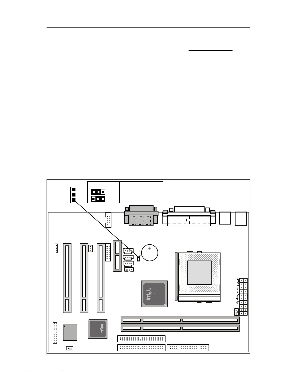
This section covers External Connectors and Memory Configuration. Please
refer to the motherboard layout chart for external connectors, slots and I/O
ports. Furthermore, this section lists all necessary connector pin assignments
for your reference. The locations of the connectors and ports are illustrated
in the following figures. Before inserting these connectors, please pay
attention to the orientations.
NOTICE !!!
1 . Make sure to unplug your power supply while adding or removing system
components
2. Always work on an antistatic surface to avoid possible damage to the
motherboard or other components from static discharge.
2.2 Motherboard Layout
JP1
1
JP1 Function
(1-2) Normal(Default)
(2-3) Clear CMOS
1
1
P
C
I
3
P
C
I
1
P
C
I
2
A
M
R
S
l
o
t
PRIMARY IDE (IDE1)
PGA370
1
1
1
11
1
T
A
D
A
U
X
C
D
D
1
C
D
D
2
W
a
k
e
-
O
n
-
L
A
N
I
n
t
e
l
8
1
0
C
P
U
F
A
N
1
F
W
8
2
8
0
1
A
A
P
S
/
2
T
:
M
o
u
s
e
B
:
K
e
y
b
o
a
r
d
U
S
B
C
O
M
1
V
G
A
LPT1
L
i
n
e
o
u
t
L
i
n
e
i
n
M
i
c
i
n
Game Port
LITHIUM BATTERY
CR2032
3V
1
1
S
M
C
1
1
C
O
M
2
1
J
P
1
1
1
F
w
8
2
8
1
0
FLOPPY
SECONDARY IDE (IDE2)
DIMM2
DIMM1
BIOS
SYS FAN
P
A
N
I
R
W
O
L
Page 6
TG-810+S Motherboard
Page 6
2.3 Function & Installation Instructions
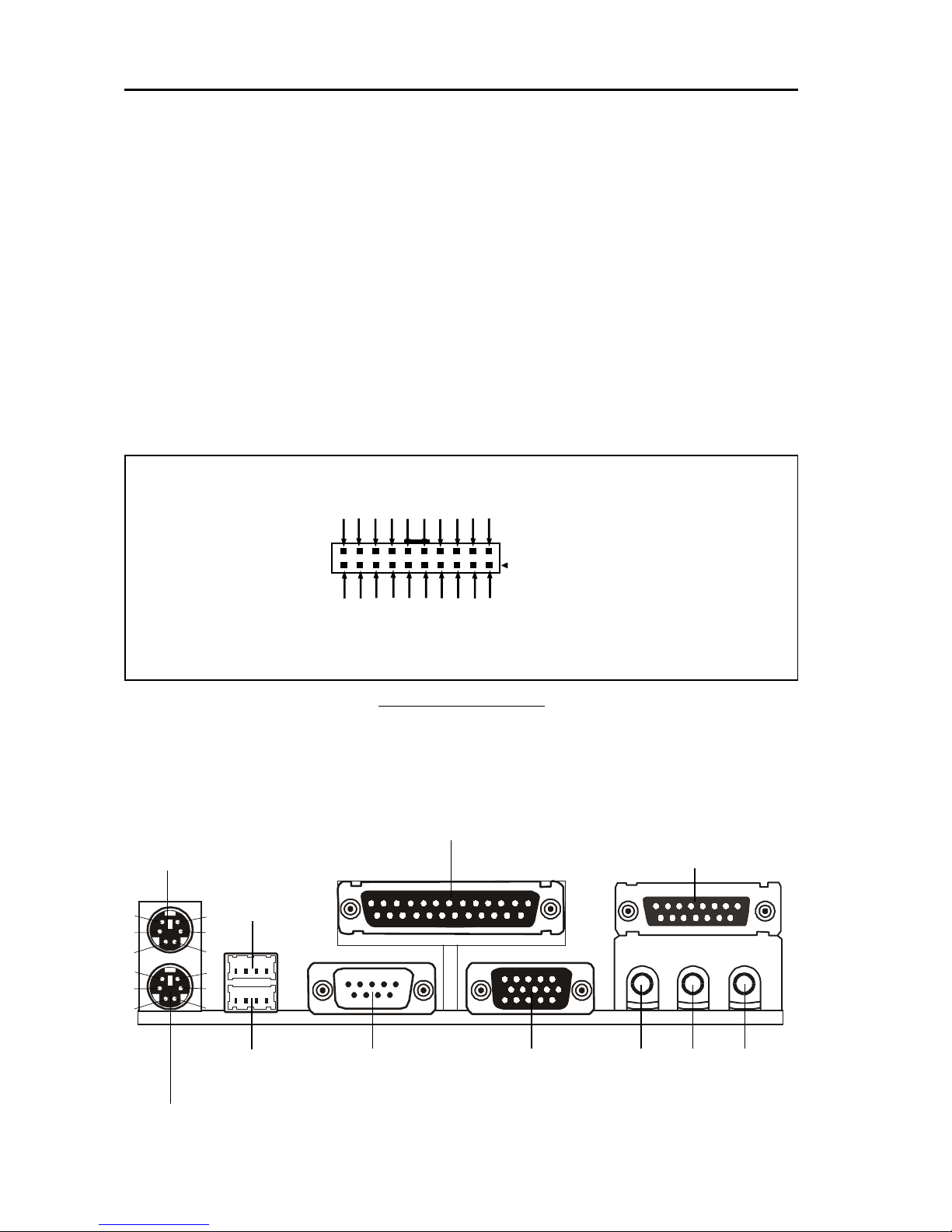
2.3.1 ATX Power Supply Connector (20-Pin)
This connector connects to an ATX power supply. The plug from ATX power
supply will only insert in one orientation because of the different hole sizes. Find
the proper orientation and push down firmly making sure that the pins are aligned.
The system power can be turned off through software control, like the shut down
in Windows 2000 / Me / 98 / 95 start menu. Power management must be enabled in
the system BIOS in order to activate this soft-off feature. Once the system BIOS
receives the power management command from the OS, it will switch the system
power off.
ATX Power Connector
2.3.2 External Connectors
Power Connector on
Motherboard
PS/2 Mouse (6-Pin Female)
PS/2 Keyboard (6-Pin Female)
USB1
USB2
COM1 VGA(15-Pin Female)
Serial Ports(9-Pin Male)
Parallel Port (25-Pin Female)
Game Port (15-Pin Female)
Line-out Line-in Mic-in
Audio Connectors
6
4
2
5
3
1
6
4
2
5
3
1
1 2 3 4
5 6 7 8
+3.3V
-12V
Ground
PW_ON
Ground
Ground
Ground
-5V
+5V
+5V
+3.3V
+3.3V
Ground
+5V
Ground
+5V
Ground
PWRGOOD
+5VSB
+12V
Page 7
Page 7
TG-810+S Motherboard
PS/2 Mouse / Keyboard Connector
Pin No. Description
1 Data
2NC
3 GND
4 VCC(+5V)
5 Clock
6NC
EXP ANSION CARDS INSTALLA TION
Before adding or removing any expansion cards or system components, confirm
that you already unplugged your power supply. Otherwise, it may severely
damage to your motherboard and expansion cards. Please follow the installation
procedures as below:
1 . Check carefully if those hardware or software settings for your expansion cards
are in the proper position as shown in their User’ s Manual.
2. Remove your computer case’ s cover and unscrew the bracket plate for those
slots needed to insert.
3 . Those expansion cards must be aligned on the slots firmly with good connection.
4. Put on the computer case cover.
5 . If needed, set up the BIOS configuration and install the required drivers for your
expansion cards.
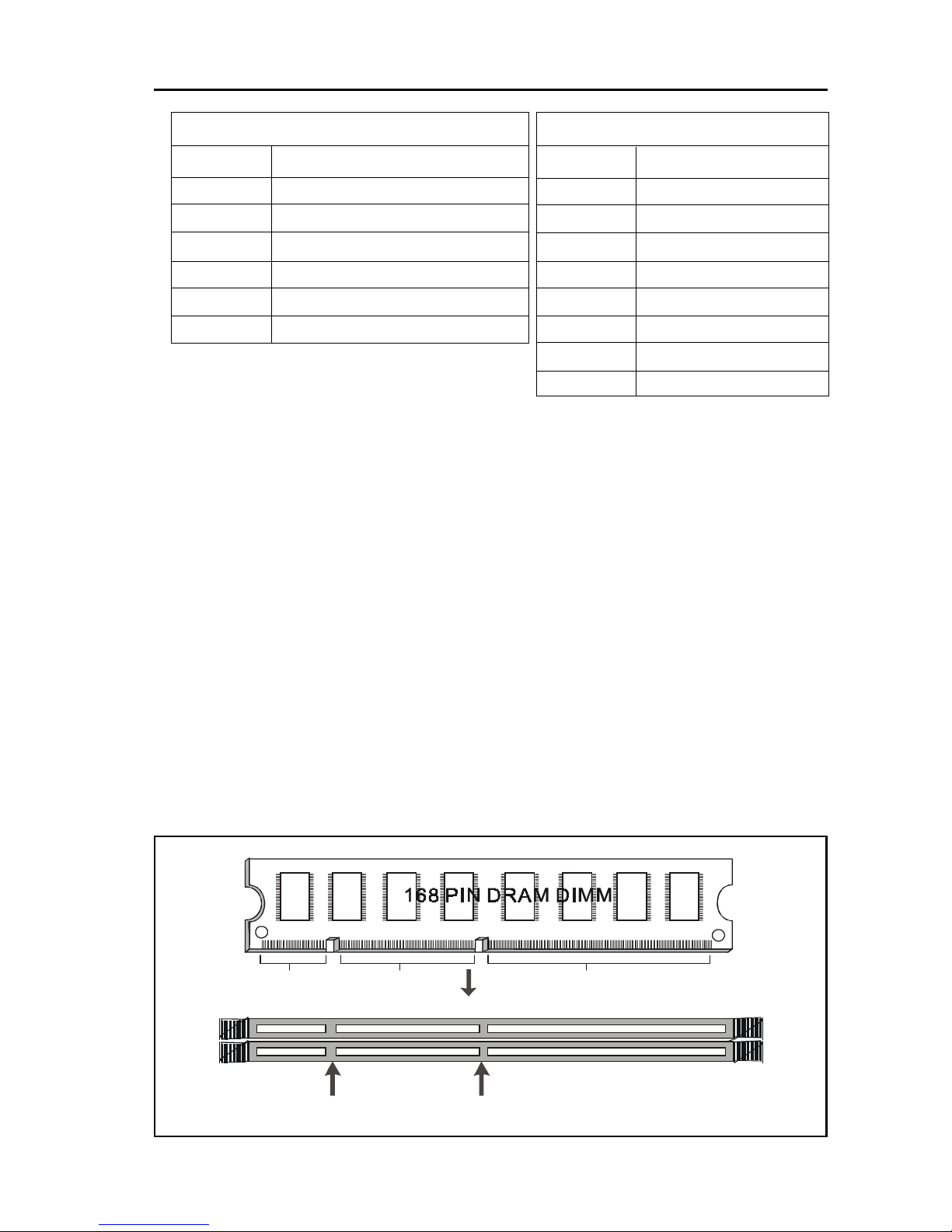
2.3.3 SDRAM Sockets
There are two SDRAM sockets on-board to provide more flexibility for your system
memory upgrade. Because the number of pins are different on either side of the
breaks, the DIMM module will only fit the 3.3V 168-pin unbuffered for this motherboard.
168-Pin SDRAM Module Installation Diagram
USB Connector
Pin No. Description
1 USB V0
2 USB D03 USB D0+
4 GND
5 USB V1
6 USB D17 USB D1+
8 GND
3.3V Key
Unbuffered
DRAM Key
20Pins 60Pins 88Pins
Lock
Two DIMM Socke t
Page 8
TG-810+S Motherboard
Page 8
2.3.4 PCI Slots
This motherboard provides three full-length 32-bit PCI slots with up to 133MB/sec
burst data transfer rate.
2.3.5 AMR Slot (Audio Modem Riser)
This connector supports a specially designed audio and/or modem card called an
AMR.
2.3.6 Floppy Drive Connector (34-Pin)
This connector supports the provided floppy drive ribbon cable. After connecting
the single end to the on-board “FLOPPY” connector, connect the remaining
plugs on the other end to the floppy drives correspondingly.
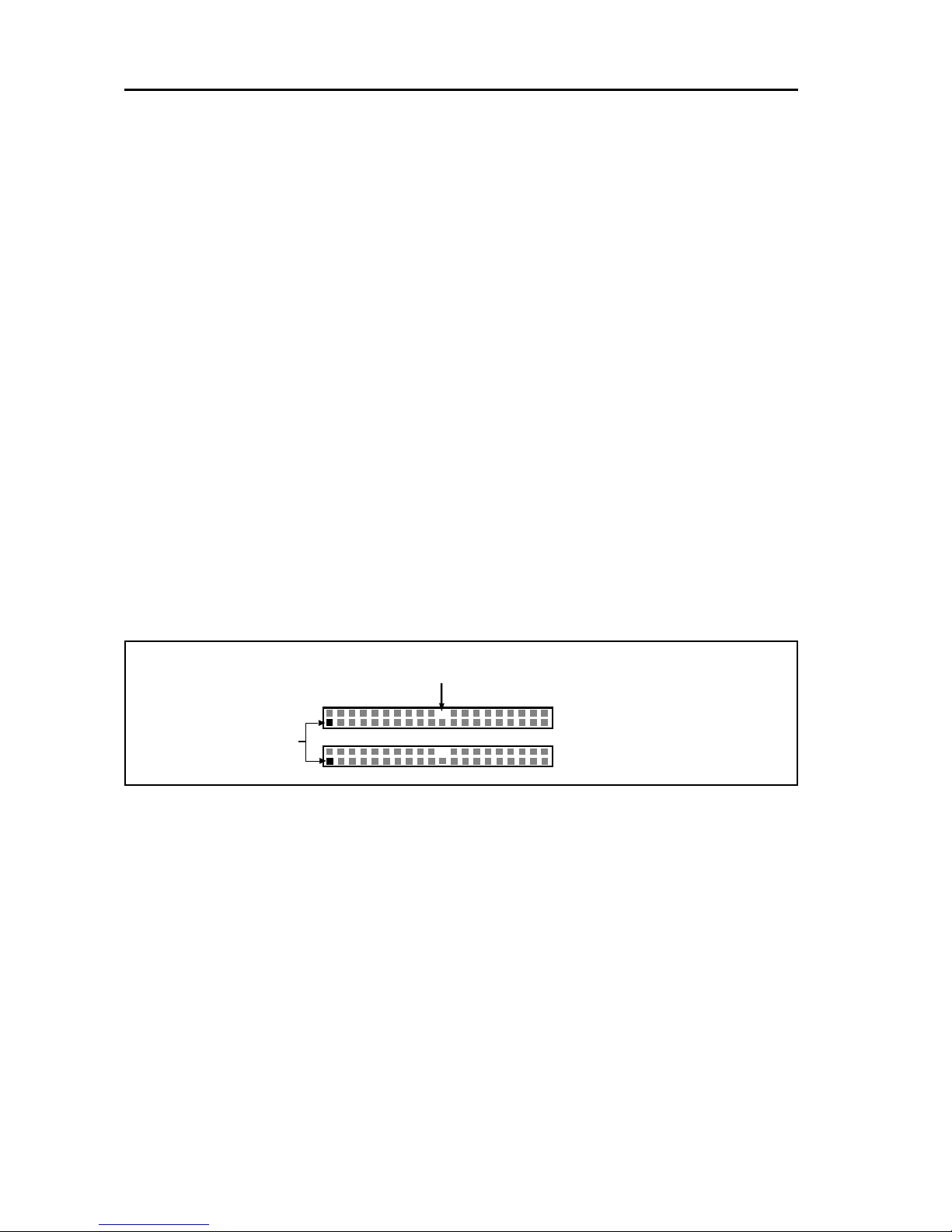
2.3.7 IDE Connectors (40-Pin)
The IDE connectors support the provided IDE HDD ribbon cable. After connecting the single end to the board, connect the two plugs at the other end to your
HDDs. If you install two IDE devices on the same cable, you must configure the
second device to slave mode by setting its jumper accordingly . (Refer to your IDE
device document for the jumper settings. Pin 20 is removed to prevent inserting in
the wrong orientation when using ribbon cables with pin 20 plugged.)
IDE Connectors
2.3.8 BIOS
The motherboard flash BIOS provides users with more flexibility in upgrading their
motherboards. The flash BIOS can be easily reprogrammed via software.
2.3.9 Wake-On-LAN Interface
This connector connects to a LAN card with a W ake-On-LAN output. The connector powers up the system when a wakeup signal is received from the network.
Pin1
Secondary IDE (IDE2)
Primary IDE (IDE1)
Pin20 be removed
Page 9
Page 9
TG-810+S Motherboard
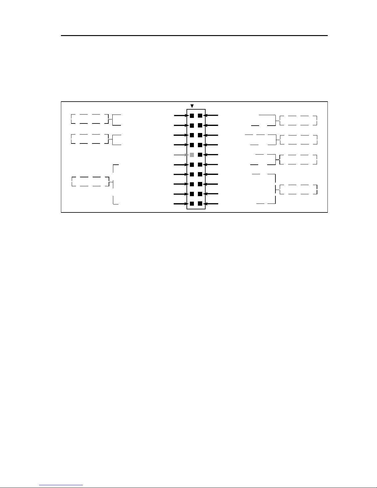
2.3.10 Front Panel Function Connector
The front panel integrates: Power On, HDD LED, Keylock, Reset Switch, Sleep,
ExtSMI, Speaker, etc...
The connector pin out are described as the figure below:
1 ATXPWRON 2 Reset Con
3 Ground 4 Ground
5 VCC 6 Sleep
7 HDD LED 8 Ground
9 No Connect 10 EXTSMI
11 PWR LED 12 Ground
13 Ground 14 Speaker
15 Ground 16 Ground
1 7 Keylock 18 Ground
19 Ground 20 VCC +5V
2.3.11 PGA370 CPU Socket
The motherboard provides a ZIF Socket 370. The CPU that comes with the
motherboard should have a fan attached to it to prevent overheating. If it is not so,
purchase a fan before you turn on your system.
Notice !!!
Be sure that there is a sufficient air circulation across the processor’ s heatsink
by regularly checking that your CPU fan is working. Without suf f ici en t circulation, the processor could be overheated and it may damage both the processor
and the motherboard. Y ou may install an auxiliary fan, if necessary.
Installation step:
1. Turn off the power of your system and remove its cover;
2. Locate the ZIF socket and open it by first pulling the lever sideways away from
the socket then upwards to a 90-degree angle;
3 . Insert the CPU with correct orientation
(The CPU has a corner pin for two of the four corners, that the CPU only fit in the
orientation.)
4 . Once completely inserted, pull down the socket’ s lever to horizontal and make
sure the CPU is firmly locked in the socket.
PWR ON
HDD LED
KEYLOCK
RESET
SLEEP
EXTSMI
SPEAKER
Page 10
TG-810+S Motherboard
Page 10
2.3.12 CPU Fan Connector
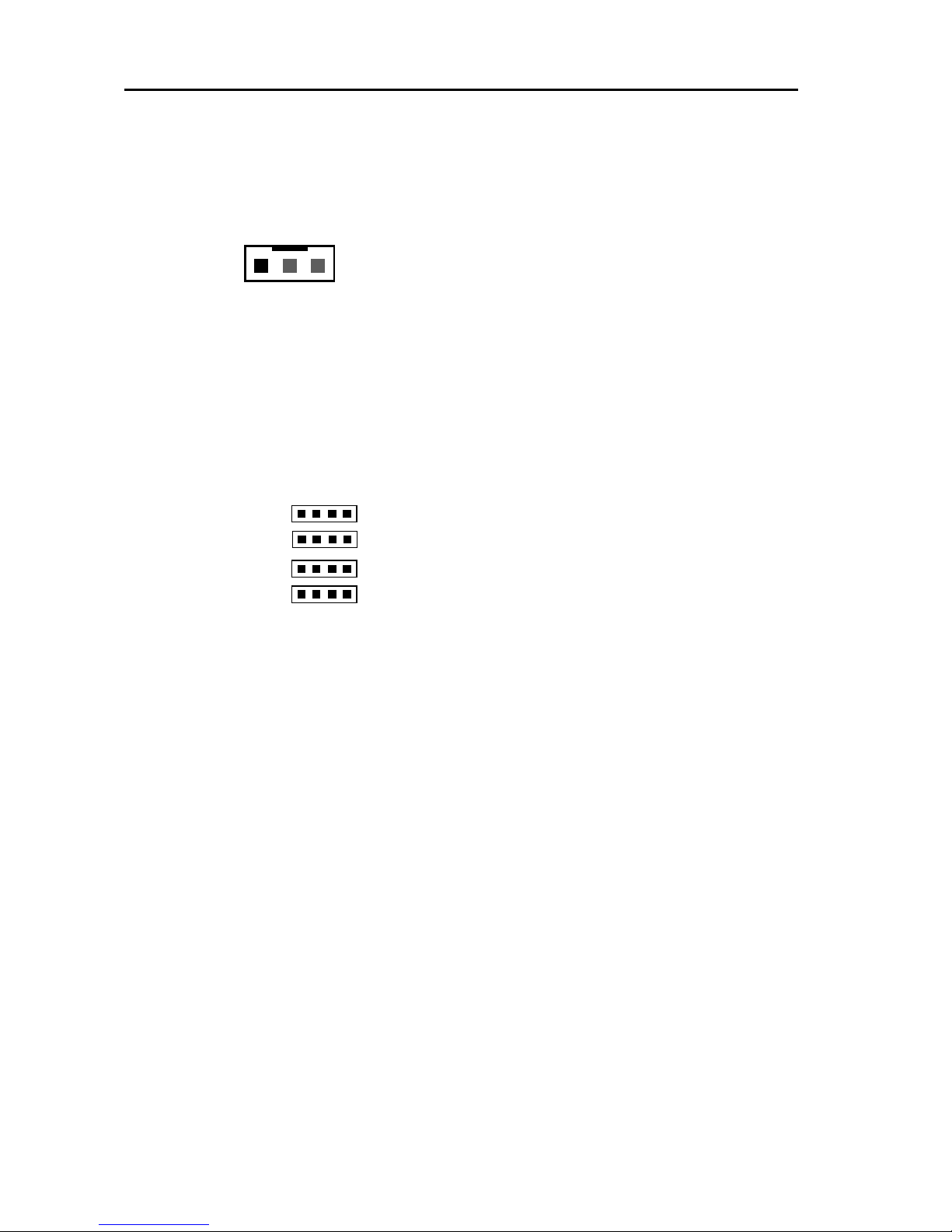
CPU Fan cable plug in the 3-pin CPU Fan connector onboard.
Pin1 Sense
Pin2 +12V
Pin3 GND
2.3.13 Internal Audio Connectors(CD, AUX, 4-pin Modem)
These connectors allow you to receive stereo audio input from sound sources such
as a CD-ROM or MPEG card. The Modem connector allows the onboard audio to
interface with an voice modem card with a similar connector. It also allows the
sharing of mono_in (such as a phone) and mono_out(such as a speaker) between
the onboard audio and the voice modem card.
TAD (Telephony Input) 1 (1: Mono_in; 2,3: Ground; 4: Mono_out)
AUX (Auxiliary Input) 1 (1: Left Audio Channel; 2,3: Ground; 4: Right Audio Channel)
CDD1 (CD Input) 1 (1,3: Ground; 2: Right Audio Channel; 4: Left Audio Channel)
CDD2 (CD Input) 1 (1: Left Audio Channel; 2,3: Ground; 4: Right Audio Channel)
1
CPUF AN
Page 11

Page 11
TG-810+S Motherboard
Chapter 3
Software Installation
Note:
Before installation, you must already have W indows 95/98/2000/Me
or W indows NT4.0 install on your computer.
The installation procedure is as below:
1. Make sure that Auto-insert detection is enabled for your CDROM drive.
It should be enabled by default.
2. Insert this CD disk into your CDROM drive.
3. The Explorer screen will then appear , that gives you instructions for
installation.
4. There may require restarts of Windows during some software setup. In
these cases, you can just eject then close the CD-tray in order to get
back to the Explorer screen. You can then proceed with the next step.
Y ou can get more information with open file: readme.txt in the CD disk.
Page 12
TG-810+S Motherboard
Page 12
Chapter 4
AMI BIOS Setup
This motherboard comes with the AMI BIOS from AMI Software Inc.
Enter the AMI BIOS program Main Menu by:
a. Turn on or reboot the system. After a series of diagnostic checks, the
following message will appear:
Press <DEL> to enter setup, ESC to skip memory test
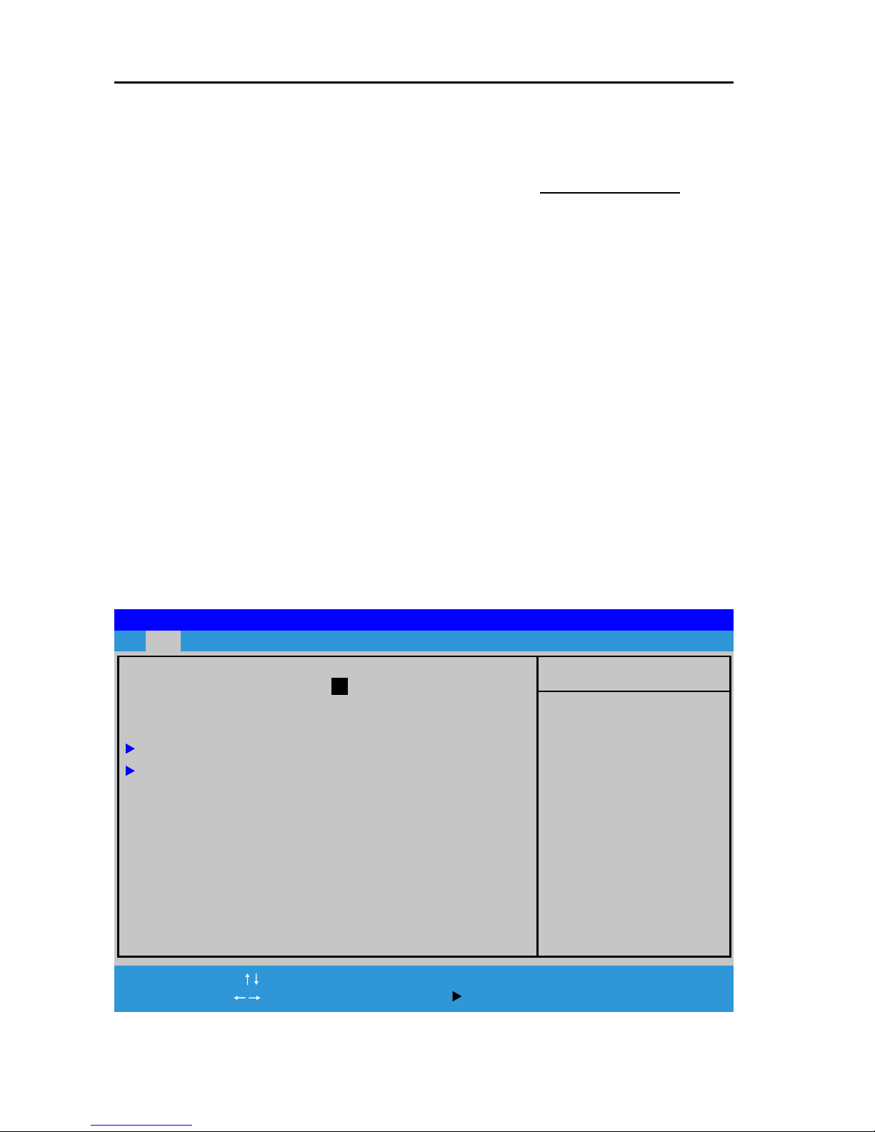
b. Press the <DEL> key and the main menu screen will appear as follows.
4.1 Main menu
The top of the screen has a menu bar, and you can select related menu. You can
use main menu this menu to make changes to the basic system configuration.
AMIBIOS EASY SETUP UTILITY - VERSION 2.01a
Main Advanced Chipset Power Peripherals Security Exit
System Time 12 : 05 : 18
System Data Mar 18 2002 Mon
Current Language English
Floppy Options
IDE Device Config
[ Setup Help ]
Time is 24 hour format
Hour: 00-23
Minute: 00-59
Second: 00-59
( 1:30AM=01:30:00
1:30PM=13:30:00)
F1: Help : Se l ect Item +/-:Change Values F9:Setup Defaults
Esc: Exit :Select Menu Enter:Select Sub-Menu F10:Save&Exit
Page 13

Page 13
TG-810+S Motherboard
Legend Bar
At the bottom of the Setup screen is a legend bar. The keys in the legend
bar allow you to navigate through the various setup menus. The following
table lists the keys found in the legend bard with their corresponding
functions.
Navigation Keys Function Description
F1 Displays the General Help screen from anywhere in
the BIOS Setup
ESC Jumps to the Exit menu or returns to the main menu
from a sub-menu
Keys Selects the menu item to the left or right
Keys Move the highlight up or down between fields
- / + keys Scrolls backward/Forward through the values for the
highlighted field
Enter Brings up a selection menu for the highlighted field
F9 Resets the current screen to its Setup Defaults
F10 Saves changes and exits Setup
Sub-menu ( )
Note that a right pointer ‘ ’ symbol. This pointer indicates that you can
display a sub-menu from this field. A sub-menu contains additional options
for a field parameter . T o display a sub-menu, move the highlight to the field
and press <Enter>. The sub-menu appears. Use the legend keys to enter
values and move from field to field within a sub-menu as you would within a
menu. Use the <Esc> key to return to the main menu.
Page 14
TG-810+S Motherboard
Page 14
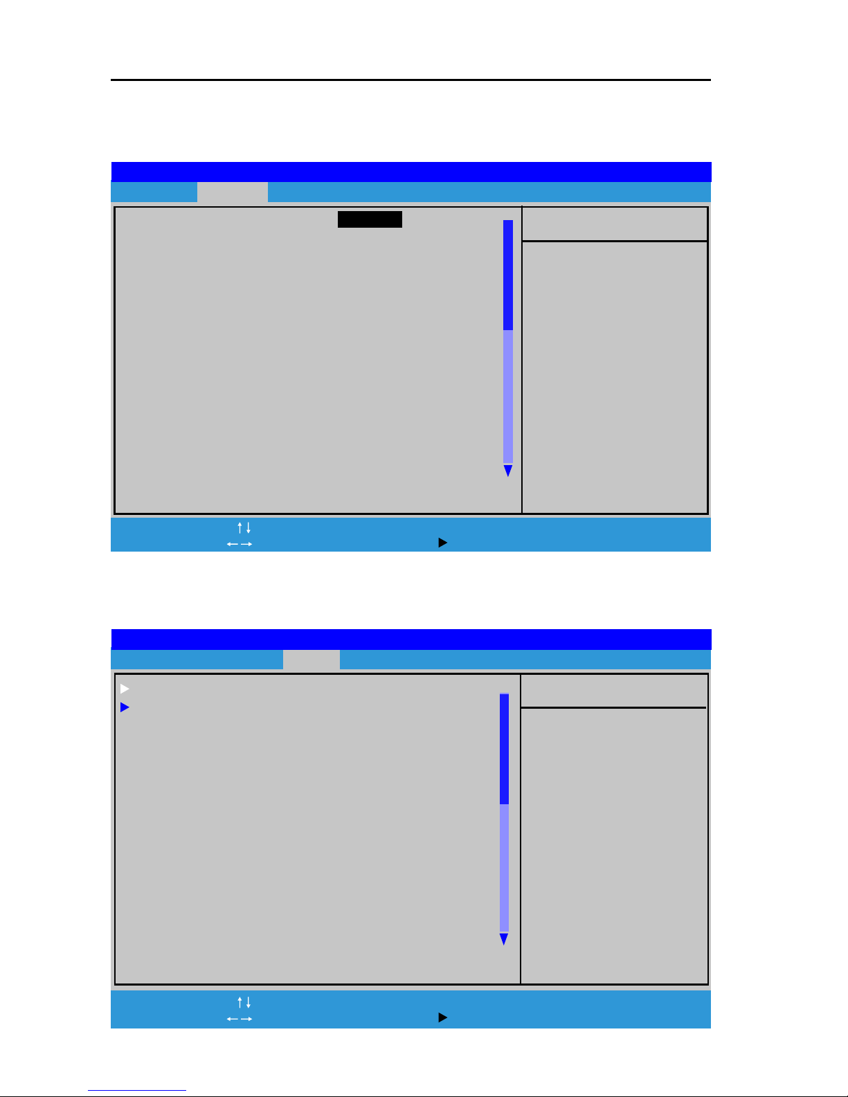
4.2 Advanced menu
Use this menu to enable and make changes to the advanced features
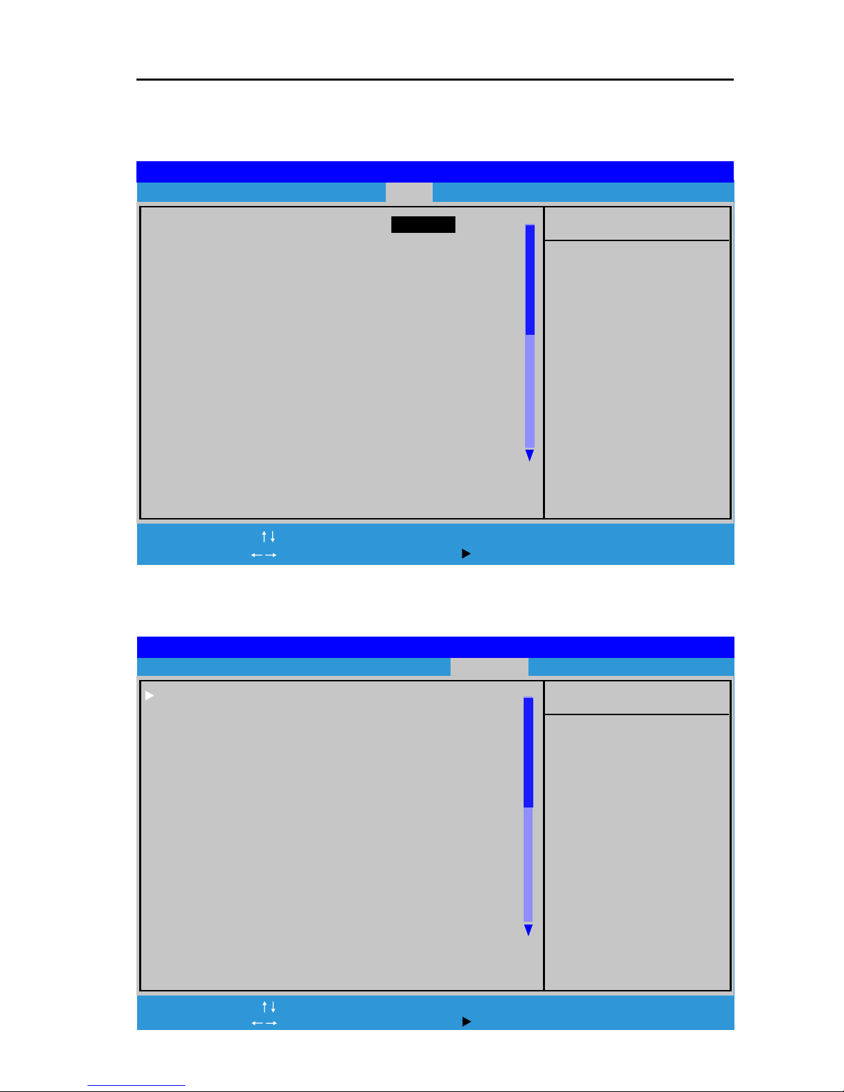
4.3 Chipset menu
Use this menu to enable and make changes to the Chipset features
[ Setup Help ]
Quick Boot Enabled
1st Floppy:1.44MB 3½
2nd IDE-0;
3rd Disabled
Try Other Boot Devices Yes
S.M.A.R.T. for Hard Disks Disabled
Boot Up Num-Lock On
Floppy Drive Seek Disabled
PS/2 Mouse Support Enabled
Password Check Setup
Boot To OS/2 No
L1 Cache Enabled
L2 Cache Enabled
System BIOS Cacheable Enabled
C000,32K Shadow Cached
C800,16K Shadow Disabled
CC00,16K Shadow Disabled
AMIBIOS EASY SETUP UTILITY - VERSION 2.01a
Main Advanced Chipset Power Peripherals Security Exit
F1:Help :Se lect Item +/-:Change Values F9:Setup Defaults
Esc:Exit :Select Menu Enter:Select Sub-Menu F10:Save&Exit
[ Setup Help ]
System Hardware Monitor
CPU Configuration
******** DRAM Timing ********
SDRAM Frequency Auto
Configure SDRAM Timing by SPD Disabled
SDRAM CAS# Latency 3 Clocks
SDRAM RAS# Precharge 2 Clocks
SDRAM RAS# to CAS# Delay 3 Clocks
SDRAM Precharge Delay 5 Clocks
SDRAM Idle Timer Infinite
SDRAM Read Thermal Management Disabled
DRAM Integrity Mode Disabled
Memory Hole Disabled
AGP Aperture Size 64MB
USB Controller All USB Port
USB Device Legacy Support Disabled
AMIBIOS EASY SETUP UTILITY - VERSION 2.01a
Main Advanced Chipset Power Peripherals Security Exit
F1:Help :Sel ect Item +/-:Change Values F9:Setup Defaults
Esc:Exit :Select Menu Enter: Select Sub-Menu F10:Save&Exit
Page 15
Page 15
TG-810+S Motherboard
4.4 Power menu
Use this menu to configure and enable Power Management features
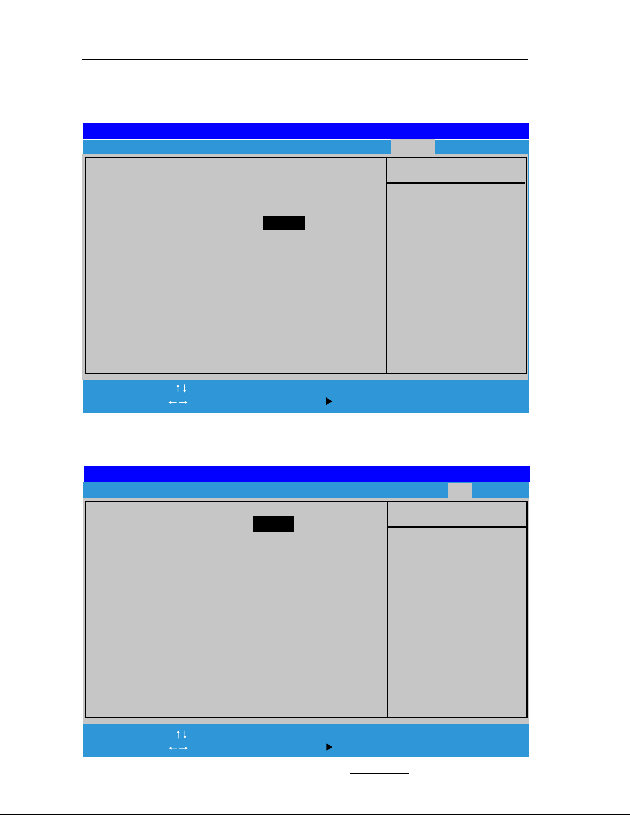
4.5 Peripherals menu
Use this menu to enable and make changes to the Peripherals features
[ Setup Help ]
Power Management/APM Enabled
Video Power Down Mode Suspend
Hard Disk Power Down Mode Disabled
Standby Time Out(Minute) Disabled
Suspend Time Out(Minute) Disabled
Throttle Slow Clock Ratio 50.0%
System Thermal Disabled
Thermal Active Temperature 65oC/149oF
Thermal Slow Clock Ratio 50.0%
Power Button Function On/Off
Restore on AC/Power Loss Power Off
Resume On Ring Disabled
Resume On LAN Disabled
Resume On PME# Disabled
Resume On RTC Alarm Disabled
RTC Alarm Data 15
RTC Alarm Hour 12
AMIBIOS EASY SETUP UTILITY - VERSION 2.01a
Main Advanced Chipset Power Peripherals Security Exit
F1:Help :Sel ect Item +/-:Change Values F9:Setup Defaults
Esc:Exit : Select Menu Enter:Select Sub-Menu F10:Save&Exit
[ Setup Help ]
PCI/Plug and Play
OnBoard IDE Both
OnBoard AC’97 Audio Auto
OnBoard FDC Auto
OnBoard Serial Port1 Auto
OnBoard Serial Port2 Auto
Serial Port2 Mode Normal
OnBoard Parallet Port Auto
Parallet Port Mode ECP
Parallet Port IRQ Auto
Parallet Port DMA Channel Auto
OnBoard MIDI Port Disabled
MIDI Port IRQ 5
OnBoard Game Port 200
K/B Power-on function Disabled
Stroke Keys Selected N/A
PS/2 Mouse Power-on function Disabled
AMIBIOS EASY SETUP UTILITY - VERSION 2.01a
Main Advanced Chipset Power Peripherals Security Exit
F1: Help :Select Item +/-:Change Values F9: Setup Defaults
Esc:Exit :Select Menu Enter: Select Sub-Menu F10:Save&Exit
Page 16
TG-810+S Motherboard
Page 16
4.6 Security menu
Use this menu to enable and make changes to the Password setting.
4.7 Exit menu
Use this menu to Saving or Discarding the BIOS setting and exit setting.
The End
F1: Help :Select Item +/-:Change Values F9: Setup Defaults
Esc:Exit : Select Menu Enter: Select Sub-Menu F10: Save&Exit
[ Setup Help ]
Specifies the
supervisor password.
AMIBIOS EASY SETUP UTILITY - VERSION 2.01a
Main Advanced Chipset Power Peripherals Security Exit
User Password Is Clear
Supervisor Password Is Clear
Set User Password [ Enter ]
Set Supervisor Password [ Enter ]
Password Check Setup
F1: Help :Select Item +/-:Change Values F9:Setup Defaults
Esc:Exit :Select Menu Enter:Select Sub-Menu F10:Save&Exit
[ Setup Help ]
Discards changes
without exiting setup
AMIBIOS EASY SETUP UTILITY - VERSION 2.01a
Main Advanced Chipset Power Peripherals Security Exit
Discard Changes [ Enter ]
Exit Saving Changes [ Enter ]
Exit Discarding Changes [ Enter ]
Load Default Settings [ Enter ]
 Loading...