

Tiga Technology T-815E+S, T-K133+S, T-K133+MS User Manual

Page 1
Thunder A TX Motherboard
Note to Users
This User’ s Guide & T echnical Reference are for assisting system manufacturers and end users in setting up and installing the motherboard. Every
effort has been made to ensure that the information in this manual is
accurate. W eal Union Development Limited is not responsible for printing or clerical errors. Information in this document is subject to change
without notice and does not represent a commitment on the part of W eal
Union. For previous or updated manuals, BIOS, drivers, or product
release information, please contact W eal Union Development Limited at
http://www .tigatech.com or through any of the means indicated on the
following pages.
Companies and products mentioned in this manual are for identification
purposes only . Product names appearing in this manual may or may not be
registered trademarks or copyrights of their respective owners.
WebSite: http://www.tigatech.com
Email: tsc@wealunion.com
Product Name: T-815E+S Classic, T-K133+S, T-K133+MS
Version: 1.00
Edition: July , 2001

Thunder A TX Motherboard
Page 2
Table of Contents
Chapter 1 Introduction .............................................................. 3
1.1 Product Features ............................................................................ 3
1.1.1 Full Software Configurable ....................................................... 3
1.1.2 T-815E+S Classic motherboard series....................................... 4
1.1.3 T-K133+S / T-K133+MS motherboard series ............................ 5
Chapter 2 Installation ................................................................. 6
2.1 Installation Instructions ................................................................. 6
2.2 Motherboard Layout ...................................................................... 6
2 . 3 Jumper Setting ................................................................................ 7
2.4 Function & Installation Instructions .............................................. 8
2.4.1 A TX Power Supply Connector ................................................. 8
2.4.2 External Connectors.................................................................. 8
2.4.3 SDRAM Sockets....................................................................... 9
2.4.4 PCI Slots ................................................................................... 9
2.4.5 ISA Slot .................................................................................... 9
2.4.6 AMR Slot.................................................................................. 9
2.4.7 AGP Slot ................................................................................... 10
2.4.8 Floppy Drive Connector ........................................................... 1 0
2.4.9 IDE Connectors ........................................................................ 1 0
2.4.10 BIOS ....................................................................................... 11
2.4.11 Wake-On-LAN Interface......................................................... 11
2.4.12 Front Panel Function Connector ............................................ 11
2.4.13 CPU Socket ............................................................................. 11
2.4.14 CPU Fan Connector ................................................................ 1 2
2.4.15 Internal Audio Connectors ..................................................... 12
2.4.16 VGA Connector ...................................................................... 12
Chapter 3 STR Installation (for T-815E+S Classic only) .................. 13
Chapter 4 Software Installation ................................................ 1 5
Chapter 5 AMI BIOS Setup ..................................................... 16
5 . 1 Standard CMOS Setup ................................................................... 1 8
5.2 Advanced CMOS Setup ................................................................. 20
5.3 Advanced Chipset Setup ............................................................... 20
5 .4 Power Management Setup.............................................................. 2 0
5 . 5 PCI/PnP Setup ................................................................................ 2 0
5 . 6 CPU Configuration Setup ............................................................... 2 0
5 . 7 Save Settings and Exit .................................................................... 2 0
5 . 8 Exit W ithout Saving........................................................................ 2 0

Page 3
Thunder A TX Motherboard
Chapter 1
Introduction
1.1 Product Features
1.1.1 Full Software Configurable
TIGA T-815E+S Classic motherboard series are full software configurable.
There is no jumper or DIP switch on board and all the necessary hardware
settings are made through CMOS setup. This motherboard auto-detects the
CPU brand and core voltage, where as the CPU speed is selected in CMOS
setup menu by the instruction of users.
In addition, TIGA T-815E+S Classic motherboard series employs AMI
BIOS which provides two start-up hot keys “J” and “F” to give a way out
of stability problems due to improper CMOS settings. That is, to press “J”
key at the same time to switch on the system, which re-detects CPU brand
and allows user to select again in the CMOS setup. T o press “F” key at the
same time to switch on the system clearing all CMOS settings (except BIOS
passwords).
Thunder A TX Motherboard
Page 4
1.1.2 T-815E+S Classic motherboard series
Support Intel Pentium III FCPGA, Celeron PPGA or Cyrix III Processor on
Socket 370
Support 66/100/133MHz Processor Front-side Bus (FSB).
Intel 82815/82801AA Chipset (not for +P option).
Integration with AGP4x Graphics Controller inside Intel 82815/82801AA chipset
(excluded with +P option)
Dynamic Graphics Memory Allocation on System Memory
Hardware Motion Compensation for Accelerated DVD V ideo Playback
High Graphics Resolution up to 1600x1200 with 8-bit Colour
Full Support for Microsoft Direct 3D and Direct Draw
Intel 82815EP/82801AA Chipset (for +P option).
Full Software Configurable: CPU Plug-and-Play and Full Jumperless
Three DIMM slots Supporting up to 768MB Memory Capacity
Support 133MHz PC133 SDRAM DIMM
Suspend-to-RAM (STR) Technology to support Instant ON
AGP 2.0 Compliant Slot Supporting 4x Mode to get 266MHz Graphics Bandwidth
1 x AMR slot, 5 x PCI slots, 1 x AGP slot
2 x USB ports, 1 x PS/2 mouse port, 1 x PS/2 Keyboard port, 1 x IrDA port
1 x FDD port, 1 x LPT port, 2 x COM ports
Dual IDE Channels Supporting Four Ultra-DMA33/66 IDE Devices
Support Keyboard and PS/2 Mouse Wakeup
Modem Ring W akeup with External Modem
Interface Header to Support W ake-On-LAN Enabled Ethernet Card
System Health Monitoring with Win95/98/Me/NT/2000 Support
AMI Flash BIOS, PC99/ACPI/DMI Compliant
A TX format, 305mm x 170mm PCB
Integrated AC97 Audio Onboard (excluded from model T-815E+ Classic)
AC97 2.1 Compliant Codec with 3D Stereo Enhancement
Complete Driver Support for Win95/98/Me/NT/2000
1 x Line-out, 1 x Line-in, 1 x Mic-in
1 x CD-in, 1 x AUX-in, 1 x T elephony Port, 1 x Game Port
Page 5
Thunder A TX Motherboard
1.1.3 T-K133+S / T-K133+MS motherboard series
Support AMD Full K7 Series of Processors on Socket A.
VIA VT8363 KT133 Chipset on model T-K133+S
VIA VT8365 KM133 Chipset on model T-K133+MS
S3 Savage4 AGP4x Graphics Controller Integrated inside VIA VT8365 chipset
(for model T-K133+MS only)
Dynamic Graphics Memory Allocation on System Memory up to 32MB
266MHz AGP4x Mode with Long Burst Transfer Rate up to 1GB/sec
Hardware Motion Compensation for Accelerated DVD V ideo Playback
128-bit 3D Architecture with 32-bit True Color Rendering
Full Support for Microsoft Direct 3D and Direct Draw
VIA VT82C686B Super South Bridge
Keyboard and PS/2 Mouse Wakeup
Modem Ring W akeup with External Modem
Interface Header to Support W ake-On-LAN Enabled Ethernet Card
Three 168-pins DIMMs, support up to 1.5GB Memory Capacity .
Support 133MHz SDRAM DIMM
AGP 2.0 Compliant Slot Supporting 4x Mode to get 266MHz Graphics Bandwidth
4x PCI slots, 1x AGP slot, 1x ISA slot.
1x FDD port, 1x LPT port, 2x COM ports
4x USB ports, 1x PS/2 mouse port, 1x IrDA port
Dual IDE channels supporting four Ultra AT A33/66/100 IDE devices
System Health Monitoring with Win95/98/Me/NT/2000 Support
AMI Flash BIOS, PC99/ACPI/DMI Compliant
A TX Format, 305mm x 190mm PCB.
Integrated AC97 Audio Onboard (excluded from model T-K133+ / T-K133+M)
AC97 2.1 Compliant Codec with 3D Stereo Enhancement
SoundBlaster Pro Hardware for DOS Mode Compatibility
Complete Driver Support for Win95/98/Me/NT/2000
1x Line-out, 1x Line-in, 1x Mic-in
1x CD-in, 1x AUX-in, 1x T elephony Port, 1x Game Port
Thunder A TX Motherboard
Page 6
P
C
I
4
P
C
I
3
P
C
I
1
P
C
I
2
DIMM2
DIMM3
A
M
R
S
l
o
t
I
n
t
e
l
8
2
8
0
2
A
B
PRIMARY IDE (IDE1)
PGA 370S
S
y
s
t
e
m
F
a
n
1
1
1
1
11
1
F
W
8
2
8
0
1
A
A
C
R
2
0
3
2
SONY
A
C
D
D
2
A
U
X
T
A
D
W
a
k
e
-
O
n
-
L
A
N
P
C
I
5
A
G
P
1
F
w
8
2
8
1
5
I
n
t
e
l
8
1
5
CPU Fan
1
1
C
D
D
1
P
S
/
2
T
:
M
o
u
s
e
B
:
K
e
y
b
o
a
r
d
U
S
B
C
O
M
C
O
M
LPT1
L
i
n
e
o
u
t
L
i
n
e
i
n
M
i
c
i
n
Game Port
1
S
M
A
R
T
C
a
r
d
1
1
DIMM1
1
I
R
PWR Fan
V
G
A
C
o
n
n
e
c
t
o
r
1
Chapter 2
Installation
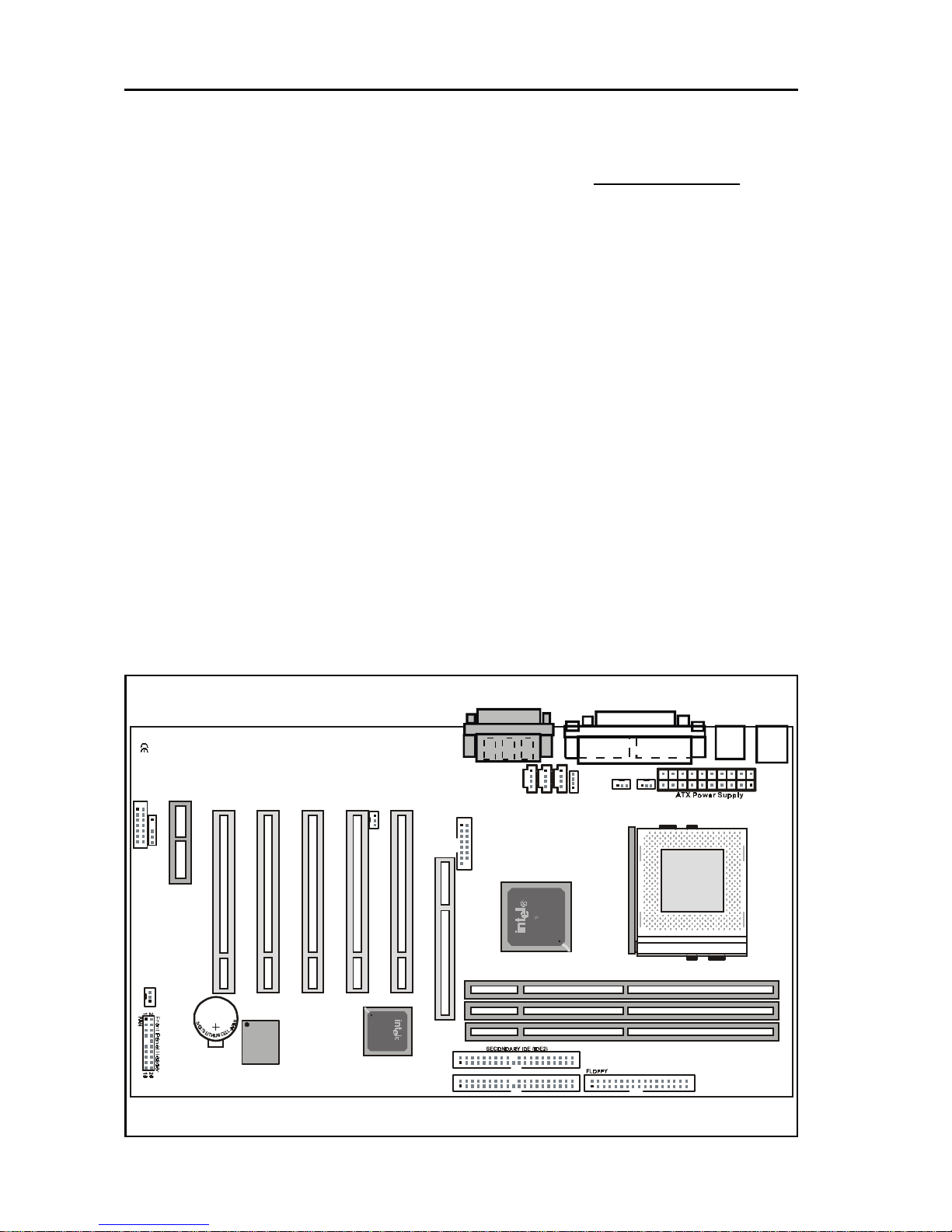
2.1 Installation Instructions
This section covers External Connectors and Memory Configuration. Please
refer to the motherboard layout chart for external connectors, slots and I/O
ports. Furthermore, this section lists all necessary connector pin assignments
for your reference. The locations of the connectors and ports are illustrated
in the following figures. Before inserting these connectors, please pay
attention to the orientations.
NOTICE !!!
1. Make sure to unplug your power supply while adding or removing
system components
2. Always work on an antistatic surface to avoid possible damage to
the motherboard or other components from static discharge.
2.2 Motherboard Layout
T-815E+S Classic Motherboard
 Loading...