

Tiffin Motorhomes PowerGlide 2019 Owner's Manual

ALLEGRO BUS POWERGLIDE CHASSIS MANUAL
TTIIFFFFIINN MMOOTTOORRHHOOMMEESS,, IINNCC..
105 2nd Street NW Red Bay, Alabama 35582 U.S.A.
2019 PowerGlide
Owner’s Manual
®
WARNING: Breathing diesel engine exhaust exposes you to chemicals known to the
State of California to cause cancer and birth defects or other reproductive harm.
• Always start and operate the engine in a well-ventilated area.
• If in an enclosed area, vent the exhaust to the outside.
• Do not modify or tamper with the exhaust system.
• Do not idle the engine except as necessary.
For more information go to www.P65warnings.ca.gov/diesel.

DISCLAIMER
ALLEGRO BUS POWERGLIDE CHASSIS MANUAL
TIFFIN MOTORHOMES, INC.
Allegro Bus Chassis Owner’s Manual
2019
Tiffin Motorhomes, Inc.
nd
105 2
Street NW, Red Bay, AL 35582 U.S.A.
Telephone 256.356.8661 • Facsimile 256.356.8219
E-Mail: info@tiffinmotorhomes.com
Many of the features and appliances described in this manual may or may not be reflected in the
actual motor home purchased, depending on the options and models selected by the motorhome
owner. All items, materials, instructions, and guidance described in this manual are as accurate
as possible at the time of printing. However, because of Tiffin Motorhomes’ ongoing and
dedicated commitment to excellence, improvement of Tiffin motorhomes is a continuing process.
Consequently, Tiffin Motorhomes reserves the right to make substitutions and improvements in
its makes and models of motorhomes without prior notification. Substitutions of comparable or
better materials, finishes, appliances, instrumentation, and instruction may be made at any time
it is deemed prudent to provide the customer with the best possible motorhome meeting the
customer’s requirements.
Copyright © 2018 by Tiffin Motorhomes, Inc. -- all rights reserved
Printed in the United States of America: Sixth U.S. Printing: June 2018
[20180601]

Tiffin Allegro Bus - PowerGlide Chassis
If you should require chassis service, you should first contact your nearest Tiffin
Customer Support
256-356-0261
Monday-Friday
6 a.m. - 4:30 p.m. CST
Powerglide®Chassis service center. Use
https://tiffinmotorhomes.com/locate_dealer/map.php to find an authorized warranty
service facility. If for some reason this is not possible or if you would like to call the
manufacturers direct, you can contact them at the following telephone numbers:
TIFFIN POWERGLIDE CHASSIS
256-356-0261
(Please have your VIN# ready)
SAFE RIDE
(Nights and weekends)
1-877-276-0619
CUMMINS ENGINE COMPANY
1-800-CUMMINS (800-286-6467)
ALLISON TRANSMISSIONS
1-800-524-2303
MICHELIN TIRE
800-TIRE-HELP (800-847-3435)
Visit our website at www.tiffinmotorhomes.com
ii

ALLEGRO BUS POWERGLIDE CHASSIS MANUAL
Table of Contents
Chapter 1
Tire Care
Tire Care 1-2
Correct Tire Pressure 1-3
Chapter 2
Allison Transmission Operation
Driving Considerations 2-2
Fluid Level Check 2-3
Chapter 3
Brake System
Brake System 3-2
Compressed Air System 3-4
Air Dryer 3-6
Engine Compression Brake 3-7
ATS Warning Lamps 4-5
DPF Maintenance 4-6
Aftertreatment Operation 4-6
Engine Indicator Lamps 4-8
Engine Starting 4-12
Cold-Weather Starting 4-13
Engine Braking (optional) 4-13
Cruise Control 4-14
Engine Shutdown 4-15
Diagnostic Fault Codes 4-15
Towing Hitch 4-16
Chapter 5
Scheduled Maintenance
Scheduled Maintenance Chart 5-2
Fluids 5-5
Lubrication Points 5-8
Maintenance Parts 5-13
Tiffin Assistance 5-15
Chapter 6
Chapter 4
Cummins Engines
Engine specs and maint. 4-2
EPA Mandates 4-4
Pre-Trip Inspection
Pre-Trip Inspection 6-2
ii

ALLEGRO BUS POWERGLIDE CHASSIS MANUAL
Chapter 7
Instruments & Controls
Graphical Instrument Cluster
Operation Guide 7-2
Overview 7-5
Indicator Quick Reference 7-6
Gauge Quick Reference 7-8
Navigation 7-9
Indicators 7-10
Gauges 7-14
Selectable Display 7-18
Alarm Messages 7-23
Menu Map 7-28
Parts Gallery 7-31
Smart Wheel Steering Wheel 7-33
Chapter 11
Allegro Club
Allegro Club Information 11-2
Chapter 8
Air Supply
Air Supply 8-2
Chapter 9
Tag Axle
Tag Axle Operation 9-2
Chapter 10
Warranty
Chassis Warranties 10-2
iii

TIRE CARE
Chapter
1
TIRE CARE
1-1
1-2
Tiffin Motorhomes: “Wherever you go…we go”
TIRE CARE
TIRE CARE
• What is the most important component of tire care?
TIRE PRESSURE
o Why?
Improved Ride
Improved Tire Wear
Improved Road Handling
Improved Braking
Tire Care
Maintaining the proper tire inflation pressure is the most important thing you can do to maximize the life of
your tires. An under-inflated tire can build up excessive heat that may go beyond the prescribed limits of
endurance of the rubber and the radial cords. Over-inflation will reduce the tire’s footprint on the road,
reducing the traction, braking capacity, and handling of your vehicle. An over-inflated tire will also cause a harsh
ride, uneven tire wear, and will be more susceptible to impact damage.
Keep in mind that the pressure rating on the side wall of your tire is the maximum pressure for that tire. This is
not necessarily the correct pressure for the tires when installed on your vehicle. Maintaining the correct tire
pressure for your vehicle’s loaded weight is extremely important and must be a part of regular vehicle maintenance.

1-3
Correct Tire Pressure
PSI=>
90
95
100
105
110
115
120
125
130
KPA=>
620
660
690
720
760
790
830
860
900
TIRE CARE
• How to determine the correct pressure:
Weigh each wheel position
Set tire pressure according to chart
Single LBS
Dual LBS
Single KG
13,340
24,280
6,060 6,300
13,880
25,580
* This Chart Shows Cold Inflation Pressures
315/80 R22.5 LRL X LINE ENERGY Z COACH
Load per Wheel-end
22.5 X 9.00” Wheel
14,380
26,180
6,520
14,880
27,760
6,740
15,220
27,760
6,900
15,840
28,840
7,180
16,540
30,440
7,500
17,380
31,640
7,880
18,180
33,080
8,250
Max
Load per
Tire
9,090
8,270
4,125
Dual KG
11,000
11,600
11,880
12,280
12,600
13,080
13,800
14,360
15,000
3,750

1-4
To determine the correct air pressure for your tires, load your motor home as you would normally travel,
including water and fuel. Go to a truck scale as found at most major truck stops and weigh each wheel
position independently, with driver and passenger(s) in the vehicle as described in the
Vehicle T ire Guide
wheel position. Then use the charts in the guide and adjust the pressure accordingly when the tires are cool or
have not been driven for more than one mile. You may call 1-800-847-3435 for a copy of the
Recreational Vehicle Tire Guide
bulletins-and-warranties/load-and-inflation-tables/#/
NOTE: Never reduce the air pressure in a hot tire.
REMEMBER: For control of your RV, it is critical that the tire pressure be the same on both sides of the axle.
(MWL43146 Rev. 03/12) to determine the correct air pressure for the weight on each
, or visit: https://www.michelintruck.com/reference-materials/manuals-
TIRE CARE
Michelin Recreational
Michelin
Emissions and Fuel Efficiency
Compliance
Your chassis was designed, and built, with components including, but not limited to, low rolling resistance tires
specifically designed and manufactured to exacting standards for regulatory fuel efficiency and greenhouse gas
emissions compliance. The vehicle owner is responsible for being sure these components are replaced with
the same or equivalent components that maintain compliance with federal and local regulations.
For help with determining tires that are the same or equal in regards to rolling resistance for maintaining
compliance with the regulatory standards, please contact Michelin at 1-800-947-3435.

2-1
Chapter
2
ALLISON TRANSMISSION OPERATION
Allison Transmission Operation

2-2
ALLISON TRANSMISSION OPERATION
Driving Conditions
• Normal driving – best fuel economy
o Select “D” and “Mode On”
• Performance
o “Mode Off”
o For mountain driving, select lower gears to maintain 2000+ engine RPM
• Hill climbing on hot days
o Keep RPMs high to cool engine
Driving Tips with the Allison 3000MH or 4000MH Transmission:
The points at which shifts occur depend upon predetermined speeds and other operating conditions. A
transmission “shift calibration” includes several sets of shift points used according to current or anticipated
operating conditions, such as engine or transmission fluid temperature. You can change shift schedules using
the MODE button.
The transmission control module (TCM) includes the capacity for two separate and distinct shift calibrations,
one for use in “Primary Mode” of operation and one in “Secondary Mode.”
Primary – This shift schedule is typically used for all normal vehicle operations.
Secondary – This is an alternate shift schedule that the TCM uses upon request. This is operatorcontrolled using the MODE button.
When you are driving under normal road conditions, the DRIVE mode is recommended for the best
performance and fuel economy. The MODE switch should be set to ON for economy mode, but MODE off
should be used when climbing hills and when extra performance is required.
The display screen on the shift control pad will indicate the highest selected gear for the transmission. When
mountainous or up-and-down terrain conditions are encountered, you should manually select a lower gear,
preferably lower than 5th gear. This can be done at any road speed by pressing the down arrow repeatedly until
the desired gear is indicated in the window of the shifter pad. When your road speed decreases to a safe point,
the transmission will downshift at a higher RPM than normal. This will decrease the use of overdrive while
pulling hills, which can result in excessive heat build-up in the transmission, and keeps the engine operating at
peak horse power and performance.
When ascending a grade, maintain engine speed to within 400-500 RPM of governed engine speed. Governed
speed will be 2200 RPM on the Cummins ISL engine model. Road speed may decrease, but the engine will be
at its peak in the power curve.
It is especially pertinent to monitor your water temperature gauge when climbing steep grades. Keep in mind
that it is not uncommon for the temperature to increase, especially in hot weather. If the gauge reaches the end

2-3
ALLISON TRANSMISSION OPERATION
zone or if the temperature warning light on the gauge panel should come on, reduce your road speed, shift to
the next lower gear and keep your tachometer within 500 RPM of engine governed speed. In many cases this
will stabilize the water temperature. If the temperature gauge continues to rise, pull to the side of the road and
shift the transmission into neutral. Bring the engine RPM to 1,700—2,000 RPM until the temperature drops
down into the normal range. This should occur in a relatively short period of time. If the temperature gauge does
not begin to drop, stays in the red zone, or continues to rise, shut down the engine and allow it to cool. After the
engine is allowed to cool check the fluid level in the reservoir and add coolant if needed.
A good “rule of thumb” for descending grades is to never use a higher gear than was used to climb the same
or similar grade. Try to keep the engine within 500 RPM of governed speed. This will give the best engine
braking and reduce the need to use the service brakes. Select a gear that will keep you at a safe speed with
minimal brake application. Never ride your brakes when descending a grade since excessive brake heat will
build up and your brakes could fade, leaving you with little or no braking power.
Your vehicle is equipped with an engine brake. The engine brake will assist in slowing your vehicle on a
downhill grade. With the engine brake switch in the ON position, release the accelerator and depress the
service brake to activate the engine brake. When the engine brake is activated the transmission will pre-select a
lower gear to aid in braking. This is indicated by a “2” in the left hand pane of the transmission shift selector.
The transmission will begin to down-shift as soon as the road and engine speed will safely allow. This will
produce a slowing effect and will remain engaged until either the exhaust brake switch is turned off, the
accelerator is pressed, or the engine speed drops to 800 RPM. If your initial speed is high, you may have to
step on the brake to slow the vehicle before the transmission will down-shift from 6th gear to 5th gear. This is
normal.
Always select (N) neutral on the transmission shift pad prior to turning off the vehicle engine.
Fluid Level Check
Use the transmission shift pad for best results in checking the transmission fluid level. The transmission will
not reach operating temperature until the coach has been driven for at least 15 miles. Therefore, it may be best
to check transmission fluid level at the end of your driving day.
Transmissions do not consume fluid. If your transmission shows to be low of fluid, it should be inspected for
leaks.

2-4
TRA NS OIL
LEVEL OK
TRA NS OIL
2QT LOW
TRA NS OIL
3QT HI
OIL TEMP
TOO LO
MUST BE IN
NEUTRAL
SETTLING
:62
ENG RPM
TOO HI
ALLISON TRANSMISSION OPERATION
Check the transmission fluid level with the following steps:
Conditions that must be met
• Be sure transmission is at operating temperature (104° to 220° F)
• Vehicle is parked on level ground with the parking brake is set
• Transmission in neutral and engine at idle
• Wait until vehicle has been stationary for two minutes
• Simultaneously press the up and down arrow keys
• Correct fluid level will be indicated by
• Low fluid level will be indicated by
• High fluid level will be indicated by
If conditions are not met one of the following messages will be displayed
• Oil temp too low
• Not in neutral
• Not stationary for two minutes
• Engine not at idle

BRAKE SYSTEM
Chapter
3
Brake System
3-1
3-2
BRAKE SYSTEM
Brake System
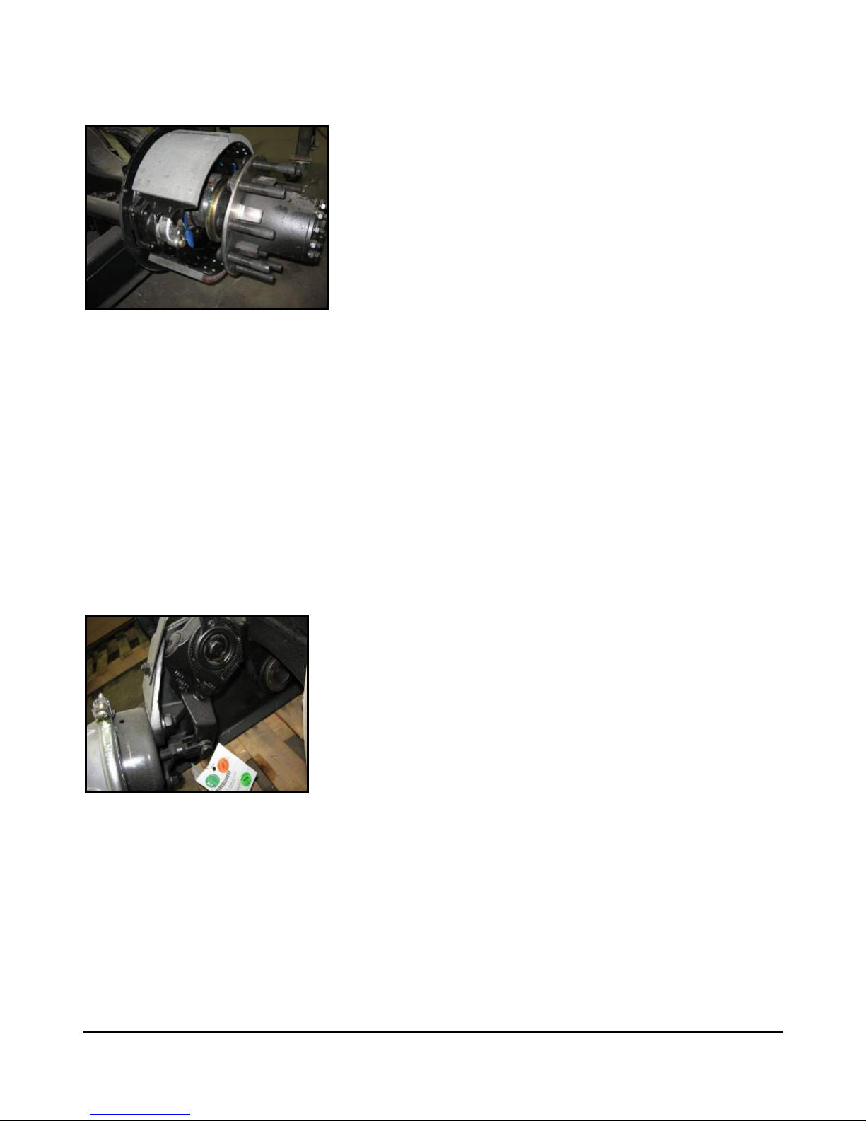
Figure 3-1: Rear Brakes
Front brakes are 17” air applied disc
Rear brakes (Figure 3-1) double as parking brake
- Park brakes are spring applied – air released
- Two large 16.5 x 7” drum brakes
- Park brake remains applied even if air pressure is lost
If air pressure is lost
- A buzzer and warning lamp will alert you
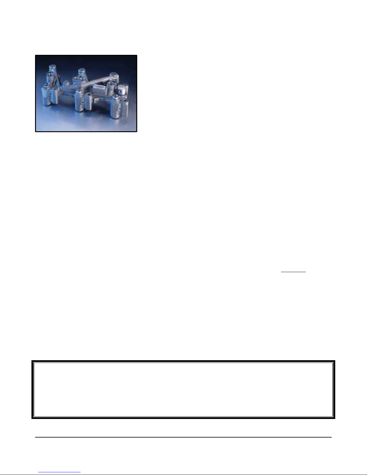
Chassis is equipped with automatic slack adjusters (Figure 3-2)
- No brake adjustment required
Figure 3-2: Automatic Slack Adjuster
The rear brakes on the PowerGlide chassis are also used as the parking brakes. This provides you the holding
power of two large drum brakes to prevent your coach from rolling, even when fully loaded on a 20% grade.
A decrease in air pressure while driving will not cause an immediate loss of brakes. If a significant leak develops
in the air system, at approximately 60 PSI you will be alerted by a lamp on the instrument panel, and by an
audible alarm. As you apply the brakes, the air supply holding the park brakes in the released position will
gradually be depleted. When system pressure drops to approximately 40 PSI the rear brakes will set. This allows
you sufficient time to pull over to the side of the road.

3-3
BRAKE SYSTEM
NOTE: The rear brakes have dual chambers – one for the service brakes and one for the park brake. The
service brakes are air applied and spring released. The park brake is spring applied and air released.
The brake system is equipped with automatic slack adjusters that avoid the need to manually adjust your brakes.
Each time you step on the brake pedal, if adjustment is needed, the adjusters will take up the slack.

3-4
Compressed Air System
36’ and 40’ Bus Non-Tag Tank Drains
BRAKE SYSTEM
3-5
43' Bus Tag Tank Drains
BRAKE SYSTEM
3-6
Warning
Air tanks should be bled of all pressure any time you perform work on the air system.
BRAKE SYSTEM
Compressed Air System
The compressed air system is comprised of multi-air storage tanks. The primary tank stores and supplies
air for the rear brakes, the secondary tank stores and supplies air for the front brakes.
When air is compressed it becomes hot. As it cools, condensed moisture forms in the system. The air system is
equipped with an air dryer to remove most of this moisture. The dryer has an automatic moisture ejector that
releases the trapped moisture back into the atmosphere. However, some moisture will form in the system
beyond the dryer, and make its way into the storage tanks. As moisture collects in the primary and secondary
tanks, it displaces the area needed for air storage, thus requiring that the tanks be drained periodically.
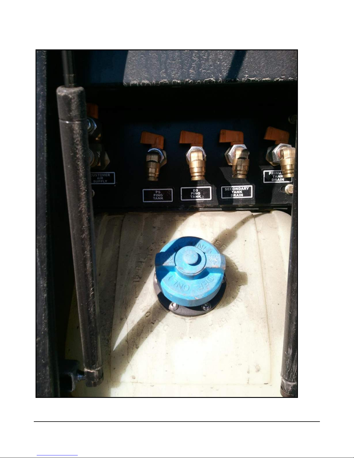
The air system is equipped with air tank drains conveniently located in the compartment with the DEF tank.
Each drain is attached to a different tank. These drains should be opened regularly for a few seconds to
remove any moisture trapped in the tanks.
Air Dryer
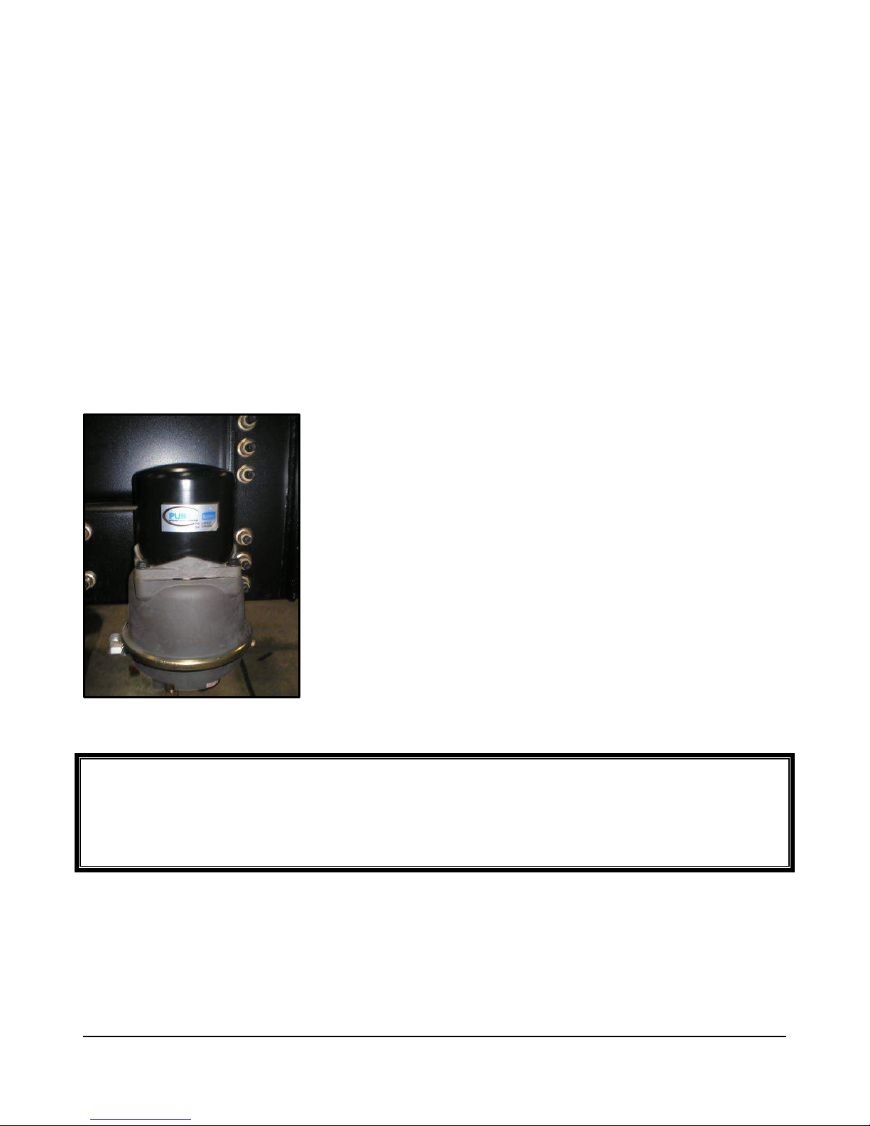
Figure 3-3: Haldex Purest Air Dryer
The Tiffin PowerGlide chassis air brake system features a Haldex Purest air
dryer (Figure 3-3), which removes the condensed moisture from
compressed air. The air dryer is equipped with a desiccant cartridge that
needs to be changed every 36 months. The dryer is located on the driver's
side (LH) frame rail (behind the rear axle).
3-7
Warning
DO NOT USE the compression brake on wet roads, hazardous, or slippery conditions.
As with any motorized vehicle, practice safety when on the road.
BRAKE SYSTEM
Engine Compression Brake
Figure 3-4: Compression Brake
The engine compression brake (Figure 3-4):
Improves braking power
Reduces the chance of overheating brakes on steep grades
Works in conjunction with the transmission to help slow the vehicle
Has two stages (low and high) for varying terrain
All brakes will build up heat when being used due to friction – this is normal. However, excessive use of the
brakes when descending a grade can result in excessive heat and can cause “brake fade” or a loss of braking
power, even with disc brakes. The proper way to use your brakes is to go slowly enough that a fairly light,
occasional use of the brakes will keep your speed from increasing.
NOTE: DO NOT maintain continual brake pedal pressure when descending a hill with any type of brake
system.
Rather, down-shift the transmission to slow the vehicle and make light, intermittent brake applications to
control downhill speeds. By utilizing the transmission gears and compression brake, continual use of the brakes
will not be necessary. When using the transmission’s lower gears to slow the vehicle on hills, be careful not to
exceed the governed speed of your engine. If engine-governed speed is exceeded, the transmission will shift up
to the next range, rapidly increasing the speed of your vehicle. If you find that you are continually using the
brakes to maintain a safe speed and to keep the RPM within this range, slow the vehicle down even further and
shift the transmission to a lower gear.

3-8
BRAKE SYSTEM
4-2
Configuration
Inline 6
Displacement
543 CU IN
8.9 L
Lube Oil Capacity
24-28 QT
23-26 L
Idle Speed
700-800 RPM
Optional Compression Brake
Up to 370 HP @ 2600 RPM
No Load Governed Speed
2400 RPM
Engine Weight (Dry)
1,695 LB
769 KG
Aftertreatment Weight
132-179 LB
60-81 KG
Chapter
4
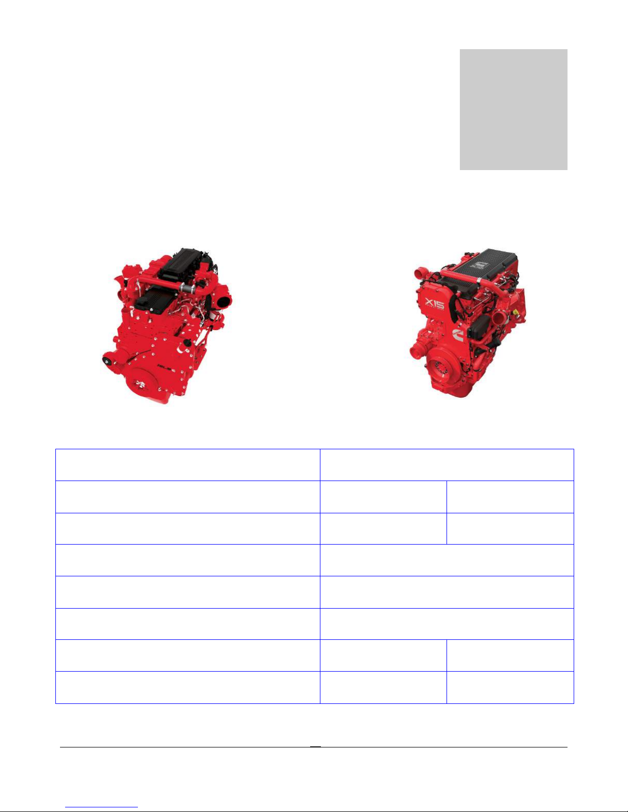
CUMMINS ENGINES
Cummins ISL & X15 Engine
________________________________________________________________________________________________________________________
Cummins ISL9 Specifications

4-3
Injection Pressure
32,000 PSI
Biodiesel Compatibility
Up to B20
Maintenance Item
Miles/Kilometers
Hours
Months
32,000 KM
32,000 KM
240,000 KM
96,000 KM
Configuration
Inline 6
Displacement
912 CU IN
14.9 L
Lube Oil Capacity
44 QT
41.6 L
Biodiesel Compatibility
Up to B20
Engine Braking Horsepower
Up to 605 HP @ 2100 RPM
Idle Speed
600-800 RPM
No Load Governed Speed
2130 RPM
Engine Weight (Dry)
2,964 LB
1,344 KG
Aftertreatment Weight*
173-211 LB
78-96 KG
Injection Pressure
32,000 PSI
Maintenance
CUMMINS ENGINES
Oil and Filter 20,000 MI
Fuel Filter 20,000 MI
Overhead Adjustment 150,000 MI
Coalescing Filter 60,000 MI
Cummins X15 Specifications
500 12
500 12
5,000 48
2,000
*Depending on configuration

4-4
Miles/Kilometers
Maintenance
CUMMINS ENGINES
Maintenance Item
Oil and Filter
Fuel Filter
Overhead Adjustment
Consult your engine Owners Manuals for more information
15,000 MI
24,000 KM
15,000 MI
24,000 KM
150,000 MI
240,000 KM
Hours Months
500 12
500 6
5,000 48
EPA Mandates
The Environmental Protection Agency (EPA) mandates that all engines built after December 31, 2009 must
reduce the level of emissions exhausted by the engine to the following levels.
Nitrous Oxides (NOx) – 0.2 g/bhp-hr
Particulate Matter (PM)- .01 g/bhp-hr
To meet EPA guidelines, diesel engines installed in Tiffin Motorhomes PowerGlide chassis for domicile
in Canada and the USA use an after treatment system (ATS) with a diesel particulate filter (DPF)to reduce
particulate matter, and selective catalytic reduction (SCR) technology to reduce NOx downstream of the
engine.
Using non-specification fluids can result in serious damage to the ATS. It is extremely important that the
following guidelines be met for vehicles with EPA10 thru EPA2017 compliant engines, or damage may
occur to the ATS, and the warranty may be compromised.
• Use "ultra-low sulfur diesel (ULSD)" with 15 ppm sulfur content or less.
• Do not use fuel blended with used engine lube oil or kerosene.
• Engine lube oil must have a sulfated ash level less than 1.0 wt %, currently referred to as CJ-4 oil.
• Use only API certified diesel exhaust fluid (DEF) in the DEF tank.
Notice

4-5
CUMMINS ENGINES
The ATS is comprised of a diesel oxidation catalyst (DOC), and a diesel particulate filter (DPF). The
DPF traps soot particles, and exhaust heat converts the soot to ash in the DPF in a process called
regeneration (re-gen). The harder an engine works, the better it disposes of soot. When the engine is
running under load and re-gen occurs without input, it is called passive re-gen. If the engine isn’t running
hot enough, the electronic controls may initiate an active re-gen, whereby extra fuel is injected into the
exhaust stream before the DPF, to superheat the soot trapped in the filter and burn it to ash. Both types
of re-gen occur without driver input.
Operating at reduced engine load will allow soot to accumulate in the DPF. When this occurs, the DPF
lamp illuminates, indicating that a re-gen must be performed, and the driver must bring the vehicle
up to highway speed to increase the load. Driving at highway speeds for 20 minutes should allow for a
re-gen to take place, and turn off the DPF lamp.
After the exhaust stream passes through the DPF, it flows through a second canister housing which is the
SCR device. A controlled quantity of diesel exhaust fluid (DEF) is injected into the exhaust stream where
heat converts it to ammonia (NH3) gas. This mixture flows through the SCR device where the ammonia
gas reacts with the NOx in the exhaust to produce harmless nitrogen (N2) and water vapor (H2O), which
then exits out of the tailpipe.
ATS War ning Lamps
Warning lamps in the driver’s message center alert you of situations with the after-treatment system.
• An illuminated DPF lamp indicates a re-gen is needed. Driving at highway speeds for 20
minutes should correct this condition.
o A blinking DPF lamp indicates the need for a re-gen is more urgent. Again, driving the
vehicle at highway speeds for 20 minutes should correct this condition.
o A blinking DPF lamp along with a check engine light indicates that the engine is unable to
effectively regenerate, and you should immediately seek service at the nearest Cummins
Authorized Dealer.
• An illuminated High Exhaust Temperature (HEST) lamp alerts the operator of elevated exhaust
temperatures while the engine is performing an active re-gen. Do not operate, or park the
vehicle near flammable objects while the HEST lamp is illuminated.
• An illuminated DEF warning lamp indicates that the DEF tank should be refilled at the next
opportunity. This light will illuminate when the tank level is at approximately 10%.
o A blinking DEF warning lamp indicates the tank level has dropped to approximately 5%.
o A blinking DEF lamp along with the check engine lamp indicates the tank level has
dropped to approximately 2.5%. A 25% reduction in engine torque will be applied with
this condition.

4-6
CUMMINS ENGINES
o When the tank is empty the Stop Engine Light will be illuminated and the vehicle speed
will be limited to 5 MPH. Filling the tank with new DEF will remedy this condition.
DPF Maintenance
Eventually ash will accumulate in the DPF and the filter will require servicing. DPF servicing must be
performed by an authorized technician, following the engine manufacturer’s instructions. DPF cleaning
will be required at approximately 200,000 miles of service. A record must be maintained for warranty
purposes, which includes:
• Date of cleaning or replacement
• Vehicle mileage
• Particulate filter part number and serial number
Aftertreatment Operation
Diesel Particulate Filter
Soot is composed of the partially burned particles of fuel that occur during normal engine operation
(black smoke).
Ash is composed of the partially burned particles of engine oil that occur during normal engine operation.
Over time, both soot and ash accumulate in the DPF and must be removed. Soot is removed by a
process called regeneration. Ash is removed by removing the DPF and cleaning it at specified intervals.
A vehicle with an ATS has up to four additional indicator lamps on the dashboard. These additional
lamps, along with the check engine lamp, alert the operator of the status of the ATS.
Ultra low sulfur diesel fuel is required for an engine equipped with a DPF. If ultra low sulfur diesel is not
used, the engine might not meet emissions regulations, and the DPF or DOC can be damaged.
To maximize the maintenance intervals of the DPF, Cummins Inc. recommends the use of a lubricating
engine oil meeting Cummins Engineering Standard 20081. The use of oil meeting CES 20081 also
requires the use of ultra low sulfur diesel fuel to maintain the specified oil drain interval without risk of
engine damage.
Regeneration

4-7
CUMMINS ENGINES
Regeneration is the process of converting the soot collected in the DPF into ash.
Under some operating conditions, such as low speed, low load, or stop and go duty cycles, the engine
may not have enough opportunity to regenerate the DPF during normal vehicle operation. When this
occurs, the engine will illuminate the DPF lamp to inform the vehicle operator that assistance is required,
typically in the form of operating the vehicle at highway speeds for approximately 20 minutes.
Heat is required for the regeneration process to occur. Regeneration can be classified into two different
types: passive regeneration and active regeneration.
Passive Regeneration
Passive regeneration occurs when the exhaust temperatures are naturally high enough to oxidize the soot
collected in the DPF faster than the soot is collected.
Passive regeneration typically occurs when the vehicle is driven at normal highway speeds and/or under
heavy loads.
Active Regeneration
Active regeneration occurs when the exhaust temperatures are not naturally high enough to oxidize the
soot in the DPF faster than it’s collected.
Active regeneration requires assistance from the engine in to increase the exhaust temperature. This is
typically accomplished by the engine injecting a small amount of diesel fuel into the exhaust stream,
which is then oxidized by the DOC, and creates the heat needed to regenerate the DPF.
Active regeneration will occur more frequently in vehicles operated at low speed, low load, or stop and go
duty cycles. Active regeneration only occurs if the engine ECM has detected that the DPF restriction has
reached a specified limit, and may only occur if the vehicle is moving above a preset speed threshold. The
engine ECM will activate and de-activate active regeneration as needed.
Active regeneration is largely transparent to the vehicle operator, the vehicle operator may notice an
increase in turbocharger noise during an active regeneration event, and may notice that the high exhaust
temperature lamp is illuminated, if the vehicle is so equipped.
During active regeneration, the exhaust temperature can be hotter than when the engine is operating at
full load. The exhaust temperature during a normal active regeneration event could reach 1100°F, and
possibly 1500°F under certain conditions.

4-8
CUMMINS ENGINES
Warning
Active regeneration can occur any time the vehicle is moving, and the exhaust temperature can remain
hot after the vehicle has stopped moving. The exhaust temperature could reach 1500°F, which is hot
enough to ignite or melt common materials, or to burn people. If the HEST lamp is illuminated do not
operate or park the vehicle with the exhaust near people, or flammable materials.
Aftertreatment Warm-up
The ATS warm up function is used to help prevent the buildup of water condensation in the ATS during
extended idle operation.
After approximately four hours of engine idle operation, the engine speed will increase to around 1100
RPM, and remain at this speed for 10 minutes. During this time the ATS is warmed up enough to
evaporate any water that has condensed in the system.
The ATS warn-up function can be stopped by depressing the throttle, clutch, or brake pedal. If the
engine continues to idle, the ATS warm-up function will try to raise the idle speed until the ATS
temperatures are suitable.
Engine Indicator Lamps
General Information
The following engine indicator lamps cover only the lamps controlled by the engine ECM.
Wait to Start Lamp
The WAIT TO START lamp illuminates when the intake air heater needs to warm the intake air prior to
starting the engine. The WAIT TO START lamp on time will vary depending on the ambient air
temperature.
The WAIT TO START lamp is amber and looks similar to this:
.
Check Engine Lamp

4-9
CUMMINS ENGINES
The CHECK ENGINE lamp illuminates when the engine needs to be serviced at the first available
opportunity.
The CHECK ENGINE lamp is amber, and looks similar to this:
Another function of the CHECK ENGINE lamp is to flash for 30 seconds at key-on when one of the
following occurs. This flashing function is referred to as the MAINTENANCE lamp. The
MAINTENANCE lamp could flash for any of the following reasons:
o Maintenance required (if the Maintenance Monitor is enabled).
o Water-in-fuel is detected.
o Coolant level is low.
Stop Engine Lamp
The STOP ENGINE lamp indicates, when illuminated, the need to stop the engine as soon as it can be
safely done. The engine must remain shut down until the engine can be repaired.
For engines with the Engine Protection shutdown feature enabled, if the STOP ENGINE lamp begins to
flash, the engine will automatically shut down after 30 seconds. The flashing STOP engine lamp alerts the
operator to the impending shut down.
The STOP ENGINE lamp is red in color, and looks similar to this:
Malfunction Indicator Lamp (MIL)
The engine in this vehicle is required to conform to EPA Heavy Duty On-Board Diagnostic (OBD)
regulations. OBD exist to make sure the engine is operating within the prescribed emissions limits. The OBD
system monitors the ATS to detect malfunctions that adversely affect emissions. If a malfunction is detected
the malfunction indicator lamp (MIL) will illuminate, and a diagnostic fault code will be logged in the engine
control module.
The MIL lamp is amber, and looks similar to this:
Diesel Particulate Filter (DPF) Lamp
The DPF lamp indicates, when illuminated or flashing, that the DPF needs to be regenerated.
The DPF lamp is amber, and looks similar to this:

4-10
CUMMINS ENGINES
An illuminated DPF lamp indicates that the DPF needs to be regenerated at the next possible
opportunity. This can be accomplished by:
1. Changing to a more challenging duty cycle, such as highway driving, for at least 20 minutes.
2. Have a Cummins authorized repair location perform a stationary regeneration.
NOTE: Stationary regeneration is considered a normal maintenance practice and is not covered by
Cummins Inc. warranty.
A flashing DPF lamp indicates that the DPF needs to be regenerated at the next possible opportunity.
Engine power may be reduced automatically.
When the DPF lamp is flashing, the operator should:
1. Change to a more challenging duty cycle, such as highway driving, for at least 20 minutes.
2. Have a Cummins authorized repair location perform a stationary regeneration.
A flashing DPF lamp combined with an illuminated CHECK ENGINE lamp indicates that the DPF
needs be regenerated immediately. Engine power will be reduced automatically. When these lamps are
illuminated together you should immediately seek service from a Cummins authorized repair location.
NOTE: If the engine is unable to complete a DPF regeneration cycle, the STOP ENGINE lamp will
illuminate and the vehicle will have to be towed to a Cummins authorized repair location.
High Exhaust Temperature (HEST) Lamp
The HEST lamp is amber, and looks similar to this:
The HEST lamp indicates, when illuminated, that exhaust temperatures are high due to regeneration of
the DPF. The lamp could illuminate during normal engine operation or during stationary regeneration.
NOTE: The OEM determines whether or not the HEST lamp is installed on the vehicle. The OEM also
specifies the temperatures, vehicle speeds, and other conditions at which the lamp illuminates. Refer to
the OEM service manual for additional information regarding this lamp.
When this lamp is illuminated, make sure the exhaust pipe outlet is not directed at any surface or material
that will melt, burn, or explode.
o Keep the exhaust outlet away from people, and anything that can burn, melt, or explode.
o Nothing within 0.6 m [2ft] of the exhaust outlet
o Nothing that can burn, melt, or explode within 1.5 m [5ft] (such as gasoline, wood, paper, plastics,
fabric, compressed gas containers, or hydraulic lines).
o In an emergency, turn off the engine to stop the flow of exhaust.
 Loading...