

Page 1

Steadicam
®
Volt
™
LIT-817001, RevA
Page 2

Introduction 1
Volt Components 2
Get Started 7
Neutral Balance 8
Powering On 11
Operating with Volt 15
Control Box settings 19
Installing the Volt 25
Control box 27
Gimbal prep 29
Mounting Volt motors 35
Flip button 37
Adding Belts 39
Upgrading gimbals
Archer/Archer2 gimbal 45
Ultra2/Shadow gimbal 49
PRO gimbals 53
Balance Ultra2/PRO 57
Troubleshooting and Notes 61
Wiring and pin-outs 63
Contact Tiffen 65
The Tiffen Company
90 Oser Avenue
Hauppauge, NY 11788
Visit us at tiffen.com
Table of Contents
Page 3
1 2
The Steadicam® Volt™
Welcome to the future of professional Steadicam® stabilizer operating!
Working with the sled’s inertia and neutral balance, the Volt generates
an “articial bottom-heaviness” to keep the horizon level and headroom
stable. With the Volt, the operator can concentrate on precise framing,
timing, navigating, and other more interesting aspects of operating.
The strength of the roll and the tilt assistance can be individually
ne-tuned to suit the operator’s preferences, and easily adjusted for
different shots. The assistance can feel like operating a sled with a very
long drop time – easy to tilt or roll – to full gyro-simulation, with the
sled locked hard to the horizon in roll or tilt or both!
Because the sled is always balanced neutrally top-to-bottom, all
pendular effects from acceleration and deceleration are eliminated. Plus,
there is no re-balancing needed when switching to low mode!
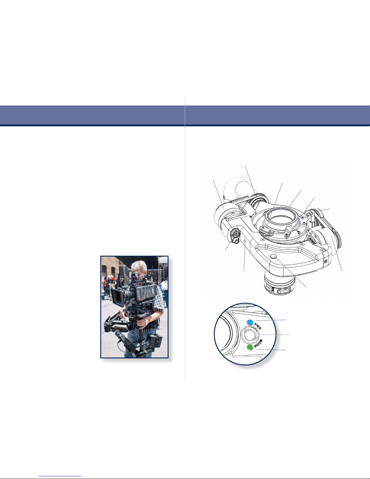
Introduction Components
Trunnion
pulley
Handle pulley
Trunnion motor
and belt
Pan encoder
Pan encoder ring
Steadicam® Volt™ shown on M-1™ gimbal
Main power/
control input &
Encoder jack
Handle motor
and belt
Power LED (blue)
Gimbal button
Mode LED (green)
Trunnion screw
access
Invert button access
The Volt also allows behaviors
that were impossible before. Like
“friction mode” which emulates a
uid head with tilt hold and a xed
horizon, bringing you new control
options for each and every shot.
In use, the Volt is completely
transparent to the operator, and it
feels exactly like regular Steadicam
operating – with perfect horizons.
The operator is always in full
and direct control of framing,
and can easily override the Volt’s
assistance.
Encoder cable guide
Page 4
3 4
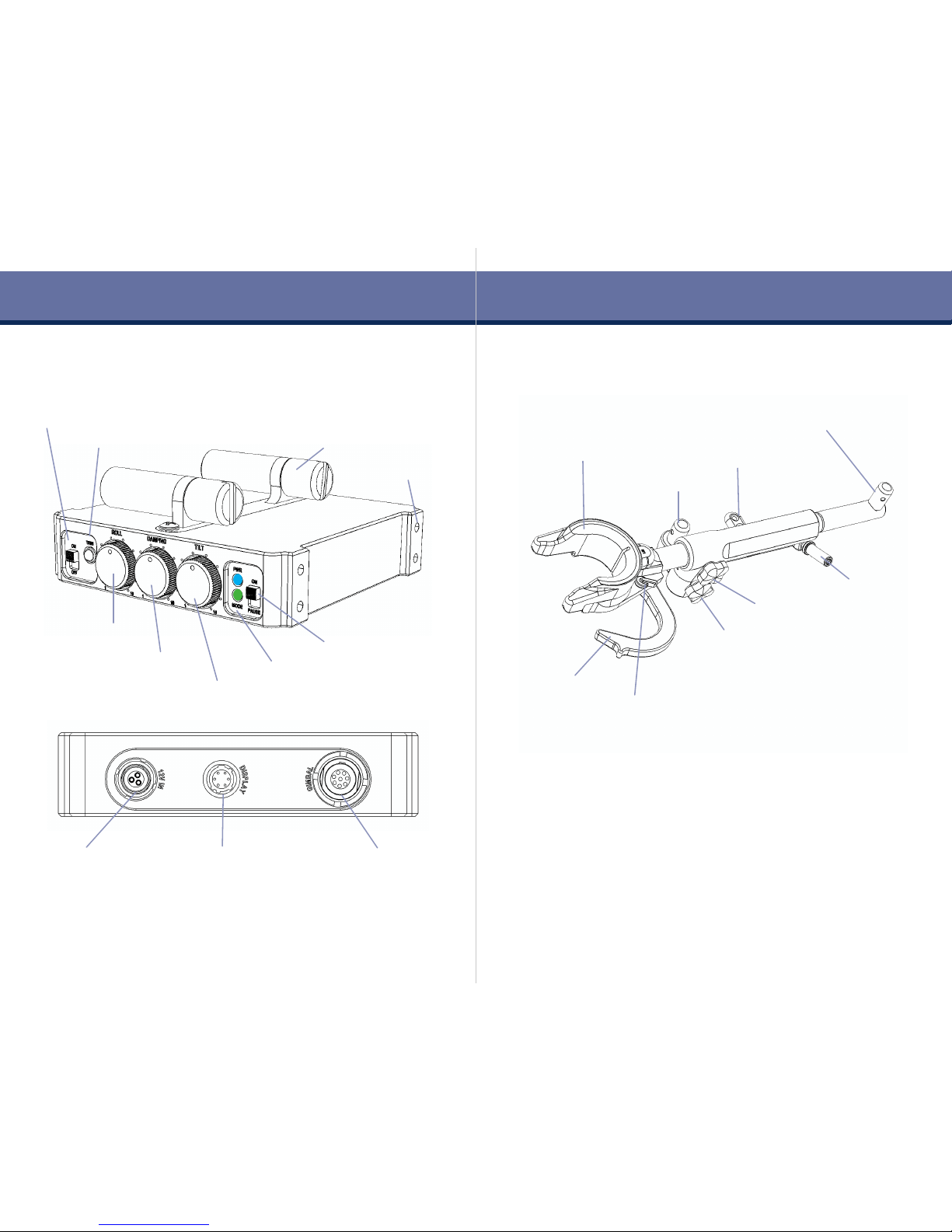
Components
Nose box rods
Power and Mode LEDs
Run/pause switch
Steadicam® Volt™ Control Box
Main power switch
Level trim button
Power input jack
from sled power
Display jack
(RESERVED)
Main power/control
output to Volt
Roll strength dial
Tilt strength dial
Damping adjuster
Steadicam® Padded Dock
The new dock
The padded dock is designed to protect the Volt electronics as well as
make docking and balancing easier. The low-prole design ensures
nothing contacts the Volt gimbal motor assembly when docked, and
the “over-center” arm swings into place to secure the sled. Docking
on the gimbal also reduces shock loads on your gimbal bearings. You’ll
note a low, primary balance stud on the side, which is barely higher
than your gimbal handle, making it a simple task to lift for balancing
regardless of the sled build.
MDR-3 mount
Dynamic balance stud
Tool holder
Arm holder
Padded dock insert
specic for your gimbal
Static balance stud
Over-center hook
Hook lock lever
Dock tilt lock knob
Stand lock knob
Note: The Lemo connectors rotate up to 90˚ in the control box chassis
to allow you more options when running cables.
Page 5

5 6
Included with Steadicam® Volt™ for M-1
• Volt Gimbal Motor Assembly (hockey stick) and pulleys
• Volt Control Box (mustache box)
• Pan encoder assembly and pan encoder ring for gimbal
• 12V power cable (817-0131)
• Gimbal cable, short (817-0135)
• Padded Dock (with insert for your gimbal) and case (817-7980)
• Nose box mounting rods
• Spare adhesive tapes for pan encoder ring
• This operation manual (LIT-817001) on USB drive
Included with Upgrade Kits for other gimbals
• Volt compatible yoke and mounting kit
• Power cable for your rig
• Blue pin wrench for your gimbal
• Mounting options you selected
• Upgrade kit details start on page 45
Tools required for installation
• Blue “whale” gimbal tool for your gimbal.
• Imperial Allen key set for install and belt adjustment.
• Flat screwdriver for nose box rods.
• Loctite® 222™ for post top screws and upgrade kits.
Components Mount options
Nose box adapter
U2, Shadow, Clipper, Archer
MDR-3 adapters
PRO or any other MDR setup
Page 6

7 8
Balance
Neutral balance
In order for the motors to exert maximum balancing assistance to
the roll and tilt axes, we balance the sled completely neutral. No drop
time at all! This also eliminates any pendulum effect when accelerating
or stopping the sled. Static and dynamic balance are now even more
critical, so panning the camera will not create diagonal forces and the
sled can easily be held at any angle without rotating.
Before you begin
The two major components of Steadicam® Volt™, the motor assembly
and the control box, contain advanced sensors and electronics.
Each may be mounted left or right, to optimize the controls for your
operating, but you must be aware of the differences these choices
present for the Volt electronics.
• The control box may be mounted for regular or goofy operators.
If your knobs are to the right of the sled (regular operator), you’ll
align the gimbal handle to the rear of the post on power up.
If your knobs are to the left of the sled (goofy operator) you’ll
align the gimbal handle to the front of the post on power up.
See page 11 about powering on.
Right knobs = REAR, Left knobs = FRONT
• Similarly, the Volt motor assembly may be mounted left or right
on the gimbal. If you’re doing this yourself, be aware that left
side is default mode and right side mounting requires pressing
the internal “ip” button once to reorient the Volt. See page 39
to learn about the ip button. If the system was installed at your
dealer, the ip procedure will have been performed already.
• We strongly encourage professional installation of the Volt
components onto your system by an authorized dealer.
• Installation instructions for Volt compatible gimbals, and upgrade
kits for other gimbals, are provided later in this manual.
• For more information visit tiffen.com/steadicam/voltsystem/
Let’s get started!
Page 7
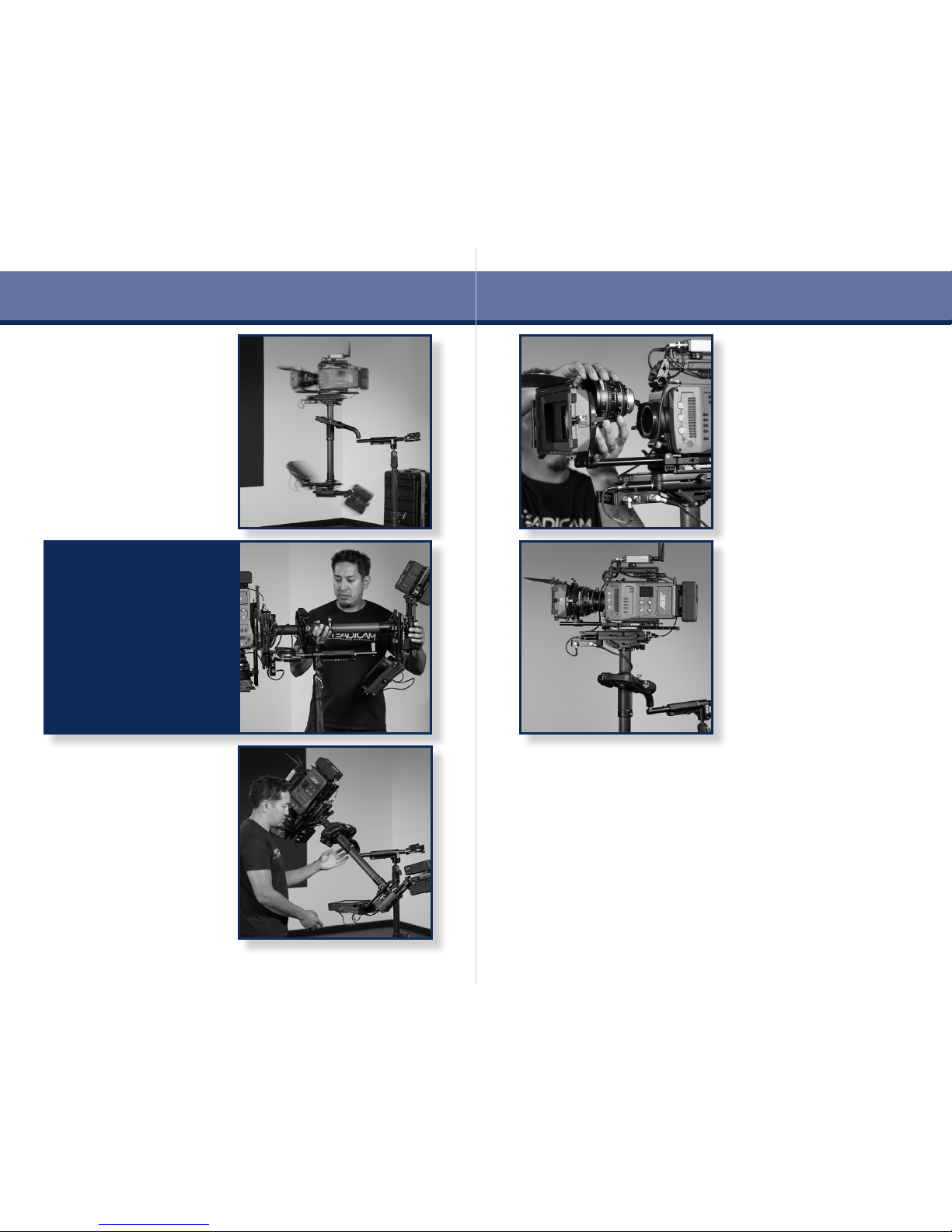
9 10
Then, change the balance to
be completely neutral top-to
bottom. It should hold any post
angle and not rotate.
TIP: For a refresher on
dynamic balancing, see
Section One of The Steadicam
Operator’s Handbook.
Balance the sled with a normal
to long drop time. BOTH static
and dynamic balance are
important here. You know how
to dynamic balance, right?
NOTE: You may wish to
temporarily unplug the gimbal
cable while dynamic balancing
to allow multiple rotations.
Make sure the sled does not
pan when holding a tilt. If so, a
tiny adjustment to your side-
side balance should correct this.
Otherwise, go back and re-
check your dynamic balance.
TIP: When you change
anything ABOVE the gimbal and
re-balance at the top stage,
dynamic balance is maintained!
When changing accessories
above the gimbal, like lenses
or lters, re-balance on the pin
with a normal drop time and
then go fully neutral again.
Balance
Page 8
11 12
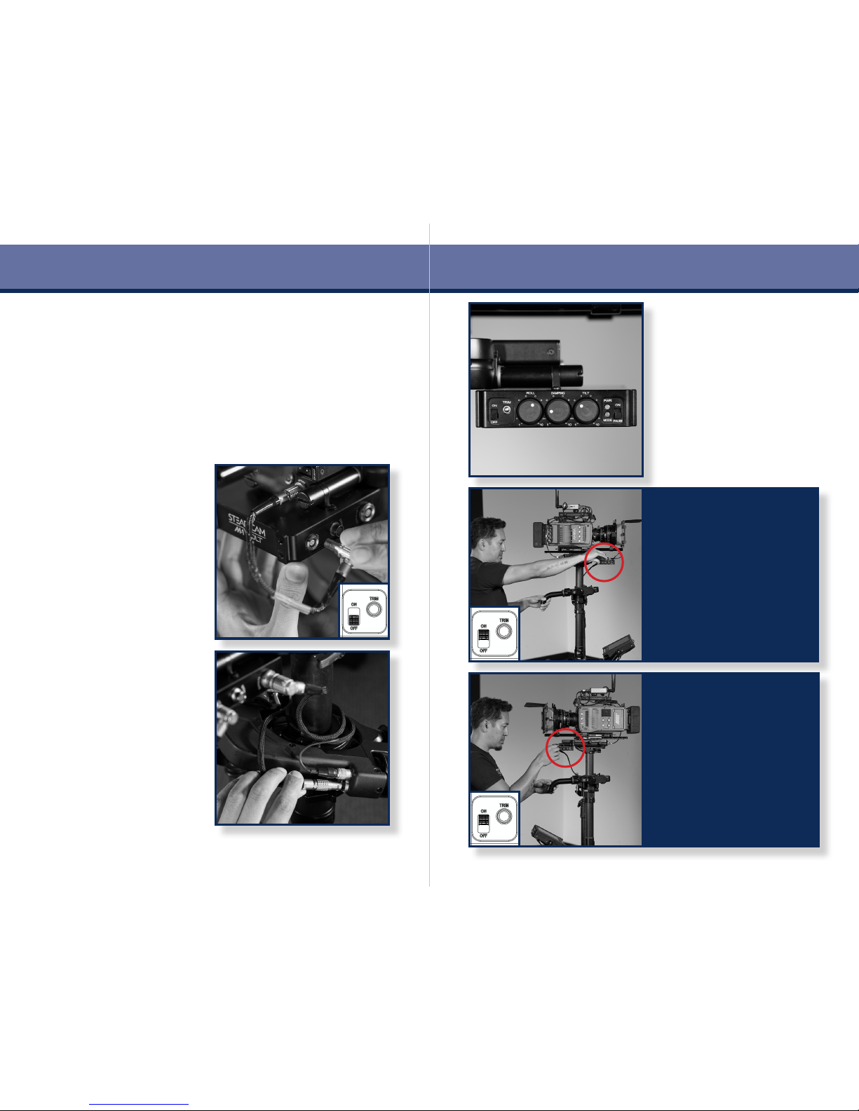
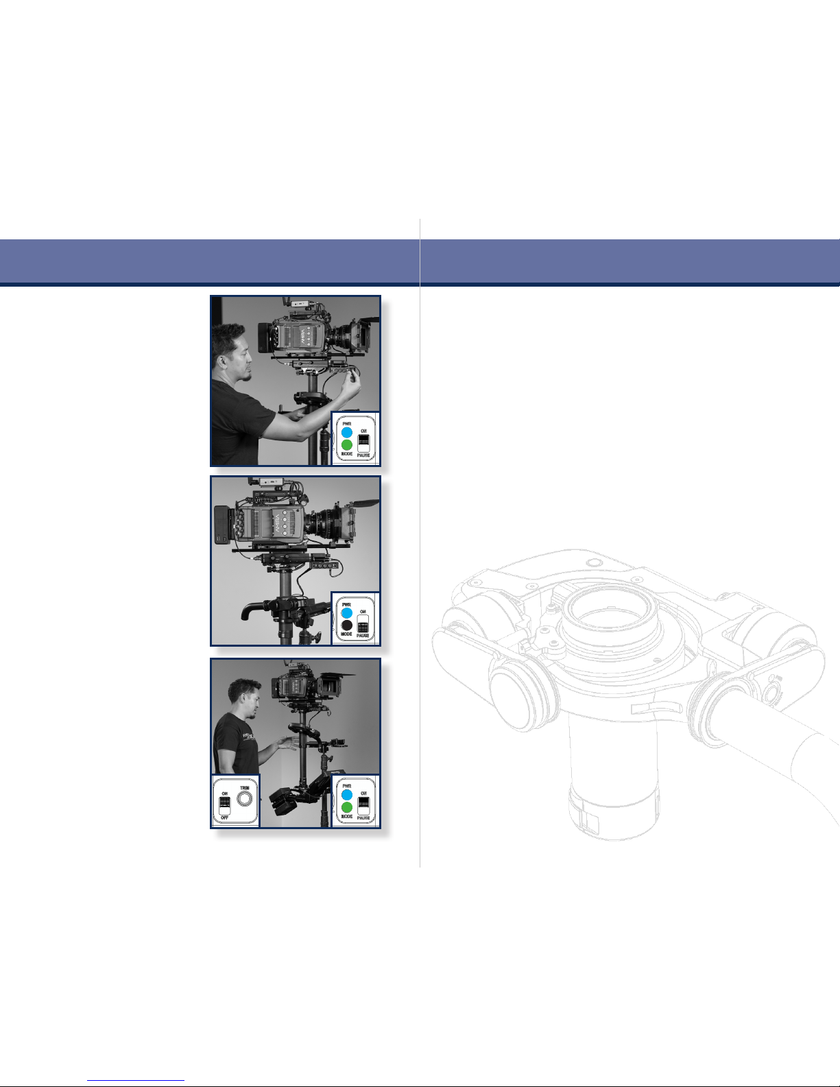
Powering up
Adding the Steadicam® Volt™ to your system requires an extra step
when powering up, and when picking up your sled. First, you’ll align
the pan encoder while powering on, and later you’ll run the system
when you want the Volt motors active. It’ll become second nature, but
pay close attention while you’re getting started for best results.
IF the control box is mounted
for regular operators (knobs
on the RIGHT) align the gimbal
handle with the REAR of the
post and simultaneously power
on the Volt. Wait 2.5sec while
the system registers the pan
encoder position.
The blue LEDs glow.
You’ll do this EVERY TIME you
power on the Volt.
Before powering on the system,
double check that the PAUSE
switch is engaged.
TIP: Consider using the Roll,
Damping and Tilt settings
shown here as a starting point.
More suggestions on page 21.
Make sure the power switch is
in the OFF position and plug in
the power cable from your sled
to the Volt control box.
NOTE: If you’re using an
aftermarket power cable,
conrm the polarity is correct.
Volt is protected against reverse
voltage, but won’t work very
well without power.
Plug in the Volt gimbal cable and
wrap a couple of loops around
the post as needed to control
any slack.
NOTE: The Volt control box will
not power up without the gimbal
cable properly connected.
IF the control box is mounted
for goofy operators (knobs
on the LEFT) align the gimbal
handle with the FRONT of the
post and simultaneously power
on the Volt. Wait 2.5sec while
the system registers the pan
encoder position.
The blue LEDs glow.
You’ll do this EVERY TIME you
power on the Volt.
Power on
Page 9
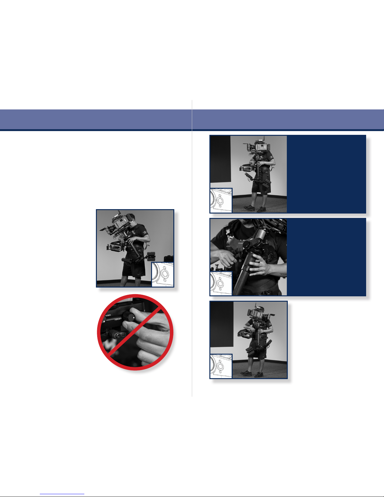
13 14
Powering on the system sets
the roll and tilt trims to default
horizon for a vertical post with
level tilt head.
In the next section, we’ll
explore trimming and modes.
Pick up the sled on your arm or
use the balance pin.
With the post vertical, ip the
pause switch to ON and the Volt
becomes active.
The green LEDs glow.
You should now feel the horizon
assistance and articial bottom-
heaviness of normal mode.
Power on
The Volt only needs to have
the post encoder aligned when
powering on.
Pausing and activating the Volt
can be toggled with the handle
in any orientation.
If you do power down,
remember to align the handle
again when powering back up.
Page 10
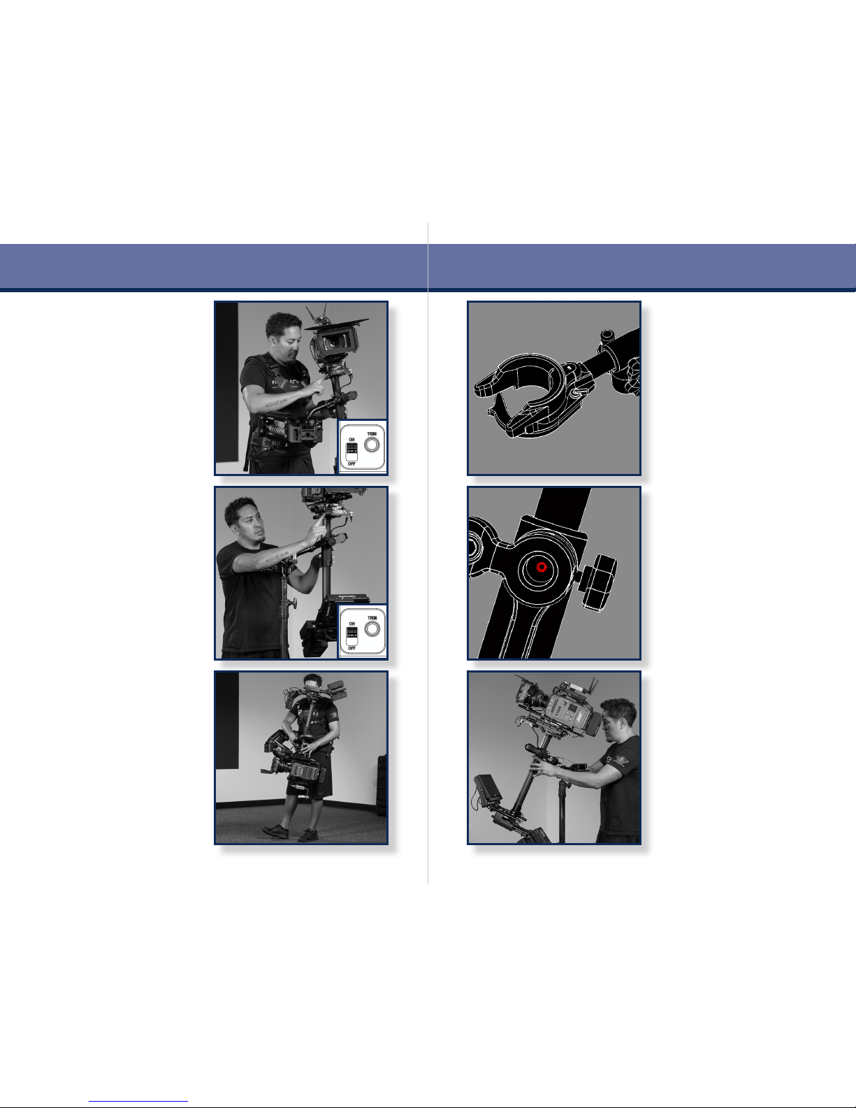
15 16
To trim, tilt the sled to any
angle and SHORT-press the
gimbal handle (thumb) button.
The new trim angle is set
immediately.
In normal mode, the articial
bottom-heaviness will return
the sled to THIS angle.
This can be done on the y,
during the shot - a huge
advantage to your operating.
Operating with the Steadicam® Volt™
The best thing about adding this tool to your system is that you’re still
operating a mechanical stabilizer, and using your skills and years of
experience to craft each shot. Here are some tips on how to optimize
the Volt, starting with trimming the post angle and the two operating
modes. We’ll adjust the control box dials later.
DO NOT TRIM with your top
stage balance like you used to...
Leave the sled in perfect neutral
balance at all times!
The two operating modes are
toggled with a LONG press of
the gimbal button.
In normal mode, the sled will
return to your trimmed tilt
angle, simulating a normally
balanced Steadicam sled.
Normal mode is always default
and displays SOLID green LEDs.
Operating
The second mode is called the
“Friction mode” and displays
PULSING green LEDs.
In friction mode, the sled
will remain tilted where the
operator places it and require
force to change tilt position.
It’s like having a uid head on
your Steadicam!
Using your sled’s integrated
tilt head maintains the vertical
post, ideal for panning.
First, pause the system, change
the tilt and re-balance the sled.
Then run the Volt and set a new
tilt trim by short pressing the
gimbal button.
Page 11
17 18
Operating
Quick low mode is now easier
than ever! When ipping,
there is no need to re-balance
because the sled is neutral.
Simply invert the sled
and rotate the monitor for
viewability.
NOTE: If you tilt the head,
make sure to set a new trim.
To reset the roll horizon to
default, LONG-press the trim
button on the control box for 6
seconds until both LEDs on the
control box turn off and pulse
back on.
Horizon is now reset.
Any previous TILT trim will be
maintained.
Should you wish to set the
ROLL trim, SHORT-press the
trim button on the control box
and position the sled to the new
level position while the LEDs
blink for 5 seconds.
When LED blinking stops,
your new horizon position (or
Dutch angle!) is now stored in
memory.
The dock offers the ability to
tilt the gimbal up to 30˚ while
remaining docked and secure.
To enable this feature, remove
the set screw from beneath the
stand mount with a 1/8” Allen
ke y.
Tilt angle is now secured with
the tilt lock knob pictured.
The included padded dock is
essential to protect the Volt’s
motors and electronics. Other
methods of docking may
damage the unit.
Always use the over-center
hook while docked.
TIP: You can remove
unnecessary docking rings and
gain precious gimbal height!
TIP: Instead of using the tilt
dock, you can also place the rig
on the balance stud and engage
the Volt motors.
Setting trim will hold the shot
with next to no operating
required!
Page 12

19 20
The pause switch is there to
keep the Volt powered on and
tracking the encoder and motor
positions.
Pausing does NOT require you
to align the gimbal handle
again, and your previous trim
setting will be maintained.
It’s great for quickly re-
balancing or standing by.
The trim button on the control
box has two functions:
• SHORT-press sets ROLL trim
to the current post angle.
• LONG-press of 6 seconds
reverts roll trim to default.
Control box settings
The three dials on the control box allow you to customize the behavior
of the Volt in two axes, roll and tilt, independently. Additionally, the
damping dial controls how the system returns the sled to vertical. Here
are some general guides to all of the control box switches and knobs.
Settings
The ROLL dial controls the
strength of the motors in the
roll axis. This equates to how
strongly the rig seeks a level
horizon side-to-side.
To help retain subtlty of control,
start with low assist levels and
add strength as needed for each
shot.
More isn’t always better!
Damping works like friction to
keep the sled from oscillating.
Set the damping in proportion
to your TILT strength, but use
as little as possible.
The operator should do most
of the damping (like normal
operating) rather than letting
the electronics do it.
The TILT dial controls the
strength of the motors in the tilt
axis. This alters the behavior:
In normal mode, more tilt
strength equates to stronger
articial bottom-heaviness.
In friction mode, more tilt
strength equates to rmer hold
at the operator’s set post angle,
like drag on a uid head.
Page 13

21 22
ROLL Dampen TILT
Recommended settings
Try these settings for the different situations listed. These recipes are
just a starting point; experiment, starting with reduced strength and
nd exactly what works best for you, for each shot.
TYPICAL MODE
Every day operating, easy tilt.
ROCK AND ROLL
Free to tilt or roll Dutch angles.
GYRO SIMULATOR
Tilt and roll set to 11.
WHIP PANS
Roll/tilt equal, vertical post.
VEHICLE MODE
High roll/tilt resistance.
FRICTION MODE
Fluid head sim, TILT is drag.
SO MANY TILTS
Normal mode, when tilting more
than 60˚ from vertical.
Additional thoughts on settings:
• Use higher motor strength in both axes for heavier rigs and rigs
with more inertia, like long mode. Less strength for lighter rigs.
• Full tilt assist is available to 22.5 degrees from vertical, HALF
assist at 45 degrees, and ZERO assist beyond 67.5 degrees,
allowing extreme tilts and a natural rest position without the
motors intervening.
• When using friction mode, increasing the TILT strength enables the
sled to “stick” to a tilt angle with more authority. It’s like the drag
setting on a uid head.
• Damping becomes LESS effective with increased motor strength
settings. Tune this to taste.
• Share settings with other Volt operators as we all explore the
future of Steadicam® operating!
• For more information visit tiffen.com/steadicam/voltsystem/
Settings
Page 14

23 24
Page 15

25 26
Installation
Installing Steadicam® Volt™ yourself
Professional installation is recommended, but a mechanically inclined,
professional Steadicam® Operator such as yourself should be able to
install a Volt in roughly an hour. But unlike other “horizon” gadgets,
you’ll probably never want to take it off!
The steps involved are:
• Before beginning you should decide two details:
1. Which side of the sled you’ll mount the control box knobs.
2. Which side you’ll mount the gimbal motors.
• Add the control box to the top stage.
• Upgrade and balance the gimbal if your gimbal is not Volt
compatible from the factory. Kits start on page 49.
• Prepare the gimbal for Volt.
• Install the gimbal motor assembly.
• Install power and gimbal cables.
• If mounting the gimbal motors on the RIGHT side of gimbal, press
the FLIP button one time while powered on.
• Sit down for a moment to mentally prepare yourself for more
creative, accurate and consistent shots!
NOTE: This portion of the manual takes you through a detailed
RIGHT-side install on an M-1 gimbal, with special notes for upgraded
gimbals and LEFT-side installs. The two sides are essentially mirror
images with minor differences.
Because specications are subject to change, visit tiffen.com/
steadicam/voltsystem/ for the latest.
Note about choosing sides
The Volt gimbal motor assembly, casually referred to as the hockey
stick, may be mounted to either side of your gimbal yoke. In general,
regular operators prefer to mount it to the left and goofy operators
mount it to the right. This allows maximum viewability of the monitor
and places the gimbal button conveniently near your thumb. However,
broadcast users may wish to test t their zoom controller onto the
handle to ensure access to the gimbal button. Also, keep in mind your
rest position may need to change if the Volt gimbal motor assembly
contacts your shoulder. The choice of side is up to you!
RIGHT side mount
(typically goofy)
LEFT side mount
(typically regular)
Page 16

27 28
Add the included short rod
extensions to the nose box of
your M-1 top stage and tighten
with a at head screwdriver.
Slide on the control box and
secure with the threaded rod
caps. Tighten with a at head
screwdriver.
Other Tiffen rigs can utilize the
nose box adapter.
Remove the three Allen screws
from the top of your nose box,
slide the adapter onto the rig
and fasten with the included
Allen screws.
Snug down the assembly by
tightening the two set screws
on the bottom.
Installing the Control Box
The control box can be mounted to the nose of your sled with the
knobs facing either side, to accommodate regular or goofy operators.
Mounting to an integrated rod system, like on the M-1 nose, is easy. If
you’re using rod adapters or MDR plates on other rigs, make sure the
control box is afxed rigidly to the sled.
Installation Control Box
Ensure the power switch is in
the OFF position and connect
the short power cable from sled
power to the 12V IN port.
NOTE: If you use an
aftermarket power cable,
conrm the polarity is correct.
Volt is protected against reverse
voltage, but won’t work very
well without power.
REMEMBER: If your box is
mounted with the knobs to the
RIGHT (regular), you’ll align
the gimbal handle to the REAR
when powering on later.
However, if your box is mounted
with the knobs to the LEFT
(goofy), you’ll align the gimbal
handle to the FRONT when
powering on later.
See page 11 about power up.
Now let’s get to the gimbal!
Page 17

29 30
Installing the Steadicam® Volt™
The initial steps for ALL gimbals require you to pull the gimbal from
your post, so take particular care if this is the rst time you’ve
disassembled the components of the system. The remaining steps can
be performed with the gimbal ON or OFF the post, though you may
nd installing the belts easier with it removed.
If you’re upgrading a non-Volt-compatible gimbal, exchange the yoke
and balance the gimbal using the notes as shown starting on page
45. Then return to this page to see how the rest goes together.
Take a moment with your blue
whale wrench to make sure
the gimbal top cap is tight and
everything spins smoothly.
Use alcohol to clean the top cap
when you’re done.
NOTE: The pan encoder ring
will cover the wrench holes.
Future gimbal servicing may
require removing the encoder.
Gimbal prep
Peel off the backing from the
four adhesive strips on the pan
encoder ring.
Careful, this stuff is sticky!
Carefully line up the two pins of
the pan encoder ring with either
two of the pin-wrench holes and
press it onto the gimbal.
Orientation is not important.
Make sure the ring sits ush
and is adhered all the way
around.
To install the pan
encoder ring onto the
gimbal of any rig, you
must remove the top
stage from the post
to gain access to the
gimbal.
The modular design
of the M-1 makes this
extremely easy.
Page 18

31 32
Installation
For M-1 gimbals, replace
BOTH covers with the supplied
threaded cap adapters using the
same pins on the blue whale
wrench.
Leave the trunnion screws in
place.
Next, if your gimbal is wearing
trunnion covers, remove BOTH
of them using the smallest pin
set on the blue whale wrench
supplied with your sled or
gimbal upgrade.
Slide the gimbal handle pulley
over the gimbal handle.
Line up the lock screws with the
four holes on the knurled blue
ring.
Use a 0.05” Allen key to tighten
the four lock screws enough to
secure the pulley. Do not over-
tighten.
TIP: If you’re upgrading a PRO
gimbal, it’s easier to install
the handle pulley during the
upgrade process.
For upgraded gimbals, install
one thread adapter ONLY on the
side of the gimbal where you
will mount the motor assembly.
Right side shown here. If
mounting Volt on the left,
thread the adapter to that side.
Leave the trunnion screws in
place.
M-1 gimbals use a 1/8” Allen
wrench to remove the small
button screw and Belleville
washer of the gimbal trunnion
from the PULLEY side.
We will be re-using the washer,
but set aside the screw.
Right side install shown.
Page 19

33 34
Installation
Gimbal upgrades will install the
pulley with bearing OVER the
trunnion screw.
The blue pin wrench is used to
secure the pulley.
For LEFT side motor installs on
any gimbal, remove the encoder
from the horseshoe bracket
with your 1/16” Allen key, and
re-route the cable so it exits
opposite the pulley side and
re-attach.
Install the trunnion pulley in
place of the M-1 trunnion screw,
with the washer behind it. Use
the narrow pins on your blue
whale wrench to tighten.
NOTE: The pulley should be
installed as shown, with the
relief around the lock screw
hole facing outwards.
With a 5/64” Allen wrench,
remove the place-holding set
screws from the two holes
opposite the gimbal handle.
Afx the pan encoder horseshoe
to the top of the gimbal, as
shown, using a 3/32” Allen
wrench to turn the included
1/2” long 8-32 button head
screws.
Use a 1/16” Allen key to attach
the pulley lock bracket to the
pulley side of the gimbal with
the included SHORT 4-40
screws.
Use the same wrench to lock
the pulley in place using the
LONG 4-40 screw (part 817-
7958) through the lower hole in
the lock bracket.
Right side shown.
Page 20

35 36
Installation
Using the 1/8” Allen key
inserted through the hole in
the side of the housing, tighten
the trunnion screw into the
threaded cap adapter.
Take your time to make sure
not to cross the ne threads.
Fully seat the fastener, but do
not over-tighten.
Before mounting the Volt
motors, check that the internal
wiring is properly routed and
the captive trunnion screw is
aligned with the housing.
TIP: Use a 1/8” Allen key to
wiggle and turn the trunnion
screw a few times to ensure it’s
seated in the Volt housing.
Hold the gimbal handle up
slightly to enable proper
clearance while installing the
Volt.
Align the relief on the inside of
the Volt and t it against the
gimbal.
Snug the opposing pair of set
screws on Volt motor assembly
with a 1/16” Allen key.
There’s one above and one
below the yoke. Tighten them
each a little until they both
contact the yoke.
Do not over-tighten.
You’re almost there!
Gimbal Motor Assembly
Thread the encoder cable
through the guide and attach it
to the horseshoe with a 1/16”
Allen key and 4-40 screws.
Plug in the Hirose cable.
Page 21

37 38
Pop out the little plastic plug
from the cover.
Use a non-metallic object to
carefully press and hold the
invert button for 3 seconds. All
LEDs will pulse off to indicate
the mode change.
Power off the unit and you’re
done ipping.
Installation
Important step for RIGHT mounted Volt
Left side mounting is default to the electronics within the Volt, so if
you mount the hockey stick on the right side, you must press the
ip button on the internal PC board. It’s just a button press, but pay
attention here.
If you mounted Volt on the LEFT side of the gimbal, skip this step!
Flip Button
Make sure the pause switch
is DOWN, indicating the Volt
motors will not run.
Switch the power ON and the
blue LEDs will illuminate.
Only press it once!
Each consecutive 3-second
press will toggle LEFT/RIGHT
side operation.
Replace the plastic cover.
NOTE: If you ip your Volt
to LEFT side mounting in the
future, you’ll have to repeat the
invert button process.
Plug in the 90˚ end of the
gimbal cable to the control box,
wrap a loop or two around the
post and plug in the Volt.
The LEMO connectors rotate
90˚ in the control box to allow
for convenient cable placement.
Page 22

39 40
With the same Allen key, turn
the trunnion motor belt tension
screw counter-clockwise, to
slide that motor toward the
gimbal.
TIP: If you’re installing belts
with the gimbal ON the rig,
stand your sled on a table so
the gimbal handle is free to
move during belt install.
First, move the handle motor as
close as possible to the gimbal
handle by turning the belt
tension screw counter-clockwise
with a 7/64” Allen key.
Adding the belts
The two belts transfer power from the Volt motors to the gimbal yoke
and gimbal handle. The belts will never stretch and should not need
replacement with normal use. Installing them will take nding the right
belt angle and rotation of the pulleys, but they are self-aligning once in
place. Let’s put on our belts!
NOTE: Right side build shown here; left side is a mirror image.
Installation Motor belts
Place the other belt over the
trunnion motor pulley and over
the top of the trunnion pulley.
Use your ngers to walk the
belt over the sidewall of the
trunnion pulley.
TIP: If the belt is stubborn, try
lifting the gimbal handle while
installing the belt to help walk it
onto the pulley
Place one of the belts (they’re
identical) over the handle pulley
and over the top of the motor
pulley.
Rotate the handle and use your
ngers to walk the belt over the
sidewall of the pulley.
Be careful not to get pinched!
Slowly adjust each belt tension,
a little at a time, so the Volt is
loaded evenly.
Adjust BOTH belt tensions by
turning each tension screw
clockwise with the 7/64” Allen
ke y.
Page 23

41 42
The belts should not have any
slack, but not be so tight as to
create friction.
Slowly adjust, test and repeat.
TIP: You may wish to adjust
the tension again with Volt
powered on to check its
behavior.
The nishing touch is to spin
the trunnion weight into the
1/4-20” threads of the trunnion
pulley.
Just make sure it’s on tight,
no need to over-torque it.
Installation
Your Volt equipped sled should now be ready
for action! Flip back to page 7, and get ready to
balance before powering on.
Plug in the 90˚ end of the
gimbal cable to the control box,
wrap a loop or two around the
post and plug in the Volt.
The LEMO connectors rotate
90˚ in the control box to allow
for convenient cable placement.
TIP: Depending on your normal
builds, you may prefer the
optional “long” gimbal cable.
If you haven’t yet, reinstall the
gimbal onto the sled.
With the gimbal lock open, slide
the gimbal back onto the post
and re-assemble the top stage.
Motor belts
Page 24

43 44
Page 25

2
1
1
1
2
.222ETITCOLYLPPA
222ETITCOLYLPPADNALABMIGECNALABER
.GNICNALABFOEMITTA
0121C410B-ICSX3
0321F8004-ICSX5
3217-503
1217-503
2217-503
1117-518X2
8
5
1
7
-
5
0
3
7317-5
13
878431-GRO
8317-513
0321B210B-ICS
108-RHW
3117-503
0121N4004-ICS
0121C2004-ICS
4217-503
108-RHW
0321B210B-ICS
6217-503
4117-503
)FER(071310-GRB
7217-503
)FER(071310-GRB
5367-008
812401-CSM
)FER(1017-503
)FER(9017-408X2
)FER(024501-GRB
)FER(724501-GRB
1
2
R
E
H
C
R
A
,
E
D
A
R
G
P
U
L
A
B
MI
G
ELBITAPMOCTLOV
9291-548-818:xaF0064-348-818:enohP
EMAN
ETAD
:STNEMMOC
REENIGNE
DEKCEHC
NWARD
SNOISIVER
L
A
I
T
N
E
D
I
F
N
O
C
D
N
A
Y
R
A
T
E
I
R
P
O
R
P
81/11/5
81-11-70
81/11/5
FRO.R
FRO.R
WM
D
C
B
8 7 65
4
3
2
1
E
F
A
VER
.ON.GWD
EZIS
:ELTIT
®
SIHTNIDENIATNOCNOITAMROFNIEHT
.ONMETIREBMUNTRAPNOITPIRCSED.YTQ
13117-503POTSLABMIG,REHSAW1
24117-503LOOTLABMIG,YSSA1
31217-503,EBUTECARRENNI1
42217-5032REHCRA,LABMIG,GNIRRETUO1
53217-503LABMIG,EGNALF1
64217-503,LABMIG,EGNALF1
76217-503LABMIG,TFAHSTOVIP1
87217-503LABMIG,REHSAW1
98517-503TLOV,EKOY1
017317-513
ESAELER
KCIUQ,ELDNAH1
118317-513LABMIG,ELDNAH1
215367-008KT"065.,LLAW"550.,EKARB1
311117-518LA
BMIG,EKOY,PAC2
41
571821
-TNIGL461.X23-8TRESNILACILEH3
51812401-CSM6#,TIBRENNAPSLLIRD1
61878431-GRO4/3X8/5X61/1,GNIR-O1
710121C2004-ICS
XEH
C_TES,61/1X04-4,WCS1
810121N4004-ICSXEHC_TES8/1X04-41
910321F8004-ICSXEHº28F4/1X04-4,WCS5
020321B210B-ICS
KLBSS8-81XEHTUB8/3x23-8,WCS
NOLFET
2
120121C410B-ICSSSPUCTES61/7X23-8,WCS3
22108-RHWSS,REHSAW8#2
DNASEHCNINIERASNOISNEMID
HSINIFSSECORPRETFAYLPPA
:SECNARELOT
LANOITCARF46/1
HCAM:RALUGNA 1 DNEB 1
X."1.
XX."10.
XXX."500.
XXXX."5000.
.R.I.T300.:YTICIRTNECNOC
010.-500.:SEGDEPRAHSKAERB
R500.-R300.:STELLIFDENIHCAM
SMR36HSINIFENIHCAM
40519AC,knabruB,.evAanoniW5182
ELGNADRIHT
NOITCEJORP
:DEIFICEPSESIWREHTOSSELNU
YB.VEROCENOITPIRCSEDETADDEVORPPA
WMA 830081ESAELERNOITCUDORP81/11/50
P
CB 560081SETONNOITCURTSNIDDA 8102/12/6
45 46
Archer/Archer2
Gimbal upgrade
It’s recommended you have an experienced Steadicam technician do
the service for you, but upgrading an Archer or Archer2 gimbal is a
fairly straightforward procedure. Here are the assembly notes used
by the factory for reference.
Visit tiffen.com/steadicam/voltsystem/ for more information.
ASSEMBLY PROCEDURE
1. REMOVE GIMBAL FROM SLED AND DIS-ASSEMBLE ALL PARTS FROM
TOP BEARING PORTION OF GIMBAL. BE CAREFUL TO NOT DAMAGE
ANY PARTS AS SOME WILL BE RE-USED UPON RE-ASSEMBLY.
2. PERFORM BEARING CLEANING OR RE-LUBRICATION IF REQUIRED.
3. PRESS BRG-105420 INTO 305-7122 OUTER RING, CAREFULLY AND
EVENLY ONLY ON THE OUTER RACE OF THE BEARING UNTIL IT IS
FULLY SEATED.
4. PRESS BOTH BRG-105427 BEARINGS INTO 305-7122 OUTER RING
CAREFULLY AND EVENLY ONLY ON THE OUTER RACE OF THE BEARING
UNTIL THEY ARE FULLY SEATED.
5. INSTALL 305-7124 ONTO 305-7101, AND ALIGN SCREW CLEARANCE SLOT WITH SCREW HOLES IN 305-7101.
6. INSTALL AND TIGHTEN SCI-4004N1210 INTO 305-7124 AND THEN
INSTALL AND TIGHTEN SCI-4002C1210 INTO SAME HOLE AND TIGHT-
EN.
7. THREAD 305-7121 INTO 305-7101 AND FULLY TIGHTEN WITH 305-
7114 WRENCH.
8. INSTALL 800-7635 INTO 305-7121.
9. INSTALL 305-7123 ONTO 305-7122 USING 3X SCI-4008F1230
SCREWS AND LOCTITE 222. NOTE ORIENTATION OF RING WITH RESPECT TO 305-7122.
10. IF GIMBAL IS NOT BEING OUTFITTED WITH A VOLT SYSTEM AT
THIS TIME, INSTALL 3X SCI-B014C1210 INTO THE THREADED HOLES
IN 305-7122. OMIT IF A VOLT SYSTEM IS TO BE INSTALLED.
11. NOTE SOME NEWER ARCHER 2 ASSEMBLIES ALREADY FITTED
WITH 315-7137 AND ASSOCIATED PARTS. IN THIS CASE, ASSEMBLY
OF 305-7158 YOKE AND ASSOCIATED PARTS ARE ONLY REQUIRED.
12. IF AN OLDER ARCHER GIMBAL IS TO BE MODIFIED, ASSEMBLE
ALL HANDLE COMPONENTS TOGETHER AS SHOWN NOTING THE USE
OF LOCTITE 222 WHERE REQUIRED.
13. INSTALL COMPLETED YOKE ASSEMBLY ONTO 305-7122 USING
2X 804-7109 ADJUSTMENT C SCREWS AND BALANCE GIMBAL AS
REQUIRED USING BALANCE PROCEDURE AND MSC-104218 SPANNER
SCREWDRIVER BIT.
14. COMPLETE ASSEMBLY BY INSTALLING 2X 815-7111 CAPS. OMIT IF
A VOLT SYSTEM IS TO BE INSTALLED.
Perform the balancing procedure found on the
next page prior to Volt installation.
Page 26

SNOISIVER
D
C
B
2
1
E
F
.ONMETIREBMUNTRA
PN
OITPIRCSE
D.
YTQ
13117-50
3P
OTSLABMIG,REHSA
W1
24117-50
3L
OOTLABMIG,YSS
A1
31217-50
3,
EBUTECARRENN
I1
42217-50
32
REHCRA,LABMIG,GNIRRETU
O1
53217-50
3L
ABMIG,EGNAL
F1
64217-50
3,
LABMIG,EGNAL
F1
76217-50
3L
ABMIG,TFAHSTOVI
P1
87217-50
3L
ABMIG,REHSA
W1
98517-50
3T
LOV,EKO
Y1
017317-513
ESAELER
KCIUQ,ELDNA
H1
118317-51
3L
ABMIG,ELDNA
H1
215367-00
8K
T"065.,LLAW"550.,EKAR
B1
311117-51
8L
ABMIG,EKOY,PA
C2
41
571821
-TN
IG
L461.X23-8TRESNILACILE
H3
51812401-CS
M6
#,TIBRENNAPSLLIR
D1
61878431-GR
O4
/3X8/5X61/1,GNIR-
O1
710121C2004-ICS
XEH
C_TES,61/1X04-4,WC
S1
810121N4004-IC
SX
EHC_TES8/1X04-
41
910321F8004-IC
SX
EHº28F4/1X04-4,WC
S5
020321B210B-ICS
KLBSS8-81XEHTUB8/3x23-8,WCS
NOLFET
2
120121C410B-IC
SS
SPUCTES61/7X23-8,WC
S3
22108-RH
WS
S,REHSAW8
#2
/12/6
47 48
Archer/Archer2
Gimbal Balancing Procedures for:
Archer 2 Series 305-7120-XX
1. Mount simulated camera weight (maximum payload capacity of sled
recommended) onto sled and place onto appropriate balance spud.
2. Fine tune fore-aft and left-right balance by adjusting fore/aft and
side/side adjustment knobs on stage. Verify balance using a bubble
level attached atop the stage on a at surface.
3. Balance sled with an approximate 3 second drop time by ne tuning
vertical position of gimbal.
4. With the front of the sled facing left, and the stage perpendicular
to the curved gimbal handle, raise the sled to the right to a horizontal
position and release until it swings back to a vertical position.
5. Unit should always return to the established vertical position. If it
does not, ne-tune the adjustment pin screws (part# 804-7109) using
included #6, 0.125” spacing spanner screwdriver and repeat the previ-
ous step.
6. To adjust pin screws remove bearing caps (815-7111) to access pin
screws
7. Gimbal ring (305-7122) to yoke (305-7158) clearance should have
zero end play but swing free, this is adjusted by turning pin screws.
8. The adjustment pin screws should have some resistance when turn-
ing.
9. If the unit is leaning to the left of vertical: turn the right adjustment
screw counter-clockwise and the left adjustment screw clockwise in
equal increments. If leaning right of vertical, reverse this procedure.
Warning: turn these screws in small increments (1/16 of turn) as
it will have a magnied affect when drop time is set at 3 seconds or
more.
10. Repeat drop test again. If unit does not repeat check to make sure
all clamps, plates, camera and whatever else might shift or become
loose is stable and not shifting the balance point.
11. Re-install bearing cap covers, if not installing Volt.
Page 27

1717-008
4717-008
0611B230D-ICS
363741-RHW
5317-518
1117-518X2
7717-008X2
573091-RHWX2
).FER(124501-GRBX2
DERIUQERSA30-/20-/10-9717-008X2
8717-008
10-8717-008
300731-NIP
30-97
17-008X2
20-9717-008X2
10-4117-503
5717-008
1
.222
ETITCOLYLPPA
2 .GNICNALABFOEMITTA222ETITCOLYLPPADNALABMIGECNALAB-ER
1
2
1
).FER(0121S0207-ICSX8
).FER(7017-008
).FER(7017-008
).FER(0121C800A-ICS
).FER(1217-008
).FER(2217-008
C
C
0121C400A-ICS
X3
0121C800A-IC
S
.ONMETIREBMUNTRAPNOITPIRCSED
60-0017-008
.YTQ
110-4117-503LOOTLABMIG,YSSA1
21717-008PMALCGNIRAEB1
34717-008PACPMALCGNIRAEB1
45717-008TLOV,EKOY1
57717-008WERCSKCOL2
68717-008PIRGELDNAH1
710-8717-008PIRGELDNAH1
810-9717-0080000.,LABMIG,NOINURT2
920-9717-008"0100.-,LABMIG,NOINURT2
0130-9717-008"0100.+,LABMIG,NOINURT2
111117-518LABMIG,EKOY,PAC2
215317-518POTSLABMIG,REHSAW1
31300731-NIP"61/3,ESAELERKCIUQ,NIP1
510121C400A-ICSXEHC_TES8/1x23-6,WCS3
610121C800A-ICSXEH
C_TES4/1x23-6,WCS1
710611B230D-ICSXEHTUB1x23-01,WCS1
81363741-RHWSS.KHT70.-40.DO44.DI91.,8#,REHSAW1
91573091-RHWELLIVELLEB"720.X"573.X"091.,REHSAW2
60-0017-008
2U/WODAHS,EDARGPULABMIG
ELBITAPMOCTLOV
C
DEIFICEPSESIWREHTOSSELNU:SETON
9291-548-818:xaF0064-348-818:enohP
EMAN
ETAD
:STNEMMOC
REENIGNE
DEKCEHC
NWARD
:EMANELIF
SNOISIVER
LAITNEDIFNOCDNAYRATEIRPORP
81/91/40
81-11-70
81/91/40
FRO.R
FRO.R
WM
D
C
B
8 7 65
4
3
2
1
E
F
A
VER
.ON.GWD
EZIS
:ELTIT
C
®
:REPGNIWARDTERPRETNI
90025.41YISNA
SIHTNIDENIATNOCNOITAMROFNIEHT
FOYTREPORPELOSEHTSIGNIWARD
YNA.YNAPMOCNEFFITEHT
ELOHWASAROTRAPNINOITCUDORPER
FONOISSIMREPNETTIRWEHTTUOHTIW
.DETIBIHORP
SIYNAPMOCNEFFITEHT
DNASEHCNINIERASNOISNEMID
HSINIFSSECORPRETFAYLPPA
:SECNARELOT
LANOITCARF46/1
HCAM:RALUGNA 1 DNEB 1
X."1.
XX."10.
XXX."500.
XXXX."5000.
.R.I.T300.:YTICIRTNECNOC
010.-500.:SEGDEPRAHSKAERB
R500.-R300.:STELLIFDENIHCAM
SMR36HSINIFENIHCAM
40519AC,knabruB,.evAanoniW5182
ELGNADRIHT
NOITCEJORP
60-0017-008
:DEIFICEPSESIWREHTOSSELNU
YB.VEROCENOITPIRCSEDETADDEVORPPA
WMA 830081ESAELERNOITCUDORP81/02/40
PCB 560081SETONN
OITCURTSNIDDA 8102/12/6
FRO.RC 0121C400A-ICS&0121C800A-ICSDDA 8102/21/7
49 50
Ultra2/Shadow/Clipper
ASSEMBLY PROCEDURE
1. REMOVE GIMBAL FROM SLED AND DIS-ASSEMBLE MAIN BEARING
HOUSING FROM GIMBAL HANDLE. BE CAREFUL TO NOT DAMAGE ANY
PARTS AS SOME WILL BE RE-USED UPON RE-ASSEMBLY.
2. PERFORM BEARING CLEANING OR RE-LUBRICATION IF REQUIRED.
3. INSTALL 800-7174 USING 8X SCI-7020S1210 SCREWS AND 222
LOCTITE. NOTE ORIENTATION OF BEARING CLAMP.
4. THREAD 800-7171 INTO 811-7107 AND FULLY TIGHTEN WITH 3057114-01 WRENCH.
5. DISASSEMBLE YOKE COMPONENTS AND THEN RE-ASSEMBLE USING NEW 800-7175 YOKE AS SHOWN NOTING THE USE OF LOCTITE
222 WHERE REQUIRED.
6. REMOVE 800-7121 SUB ASSEMBLY FROM 800-7122 BY FIRST
LOOSENING SCREW SCI-A008C1210.
7. INSTALL 800-7178 OR 800-7178-01 AS REQUIRED AND RE-ASSEMBLE 800-7121. NOTE THAT 800-7178-01 WILL BE USED FOR SLEDS
WITH A GIMBAL STAGE REMOTE AND 800-7178 FOR THOSE
SLEDS WITHOUT.
8. INSTALL COMPLETED YOKE ASSEMBLY ONTO 800-7107 USING INITIALLY 2 X 800-7179-01 PARTS ON EITHER SIDE OF YOKE.
9. BALANCE GIMBAL AS REQUIRED USING BALANCE PROCEDURE.
NOTE THAT PIN- 137003 IS USED TO INSTALL AND REMOVE 8007179-XX PARTS.
10. COMPLETE ASSEMBLY BY INSTALLING 2X 815-7111 CAPS. OMIT IF
A VOLT SYSTEM IS TO BE INSTALLED.
Gimbal upgrade
It’s recommended you have an experienced Steadicam technician do
the service for you, but upgrading an Ultra2 or Shadow gimbal is a
fairly straightforward procedure.. Here are the assembly notes used
by the factory for your reference.
Visit tiffen.com/steadicam/voltsystem/ for more information.
Perform the balancing procedure found on
page 57 prior to Volt installation.
Page 28

.ONMETIREBMUNTRA
PN
OITPIRCSED
60-0017-008
.YTQ
110-4117-503LOOTLABMIG,YSS
A1
21717-008PMALCGNIRAE
B1
34717-00
8P
ACPMALCGNIRAE
B1
45717-008TLOV,EKO
Y1
57717-008WERCSKCO
L2
68717-008PIRGELDNA
H1
710-8717-008PIRGELDNA
H1
810-9717-00
80
000.,LABMIG,NOINUR
T2
920-9717-00
8"
0100.-,LABMIG,NOINUR
T2
0130-9717-00
8"
0100.+,LABMIG,NOINUR
T2
111117-518LABMIG,EKOY,PA
C2
215317-51
8P
OTSLABMIG,REHSA
W1
31300731-NI
P"
61/3,ESAELERKCIUQ,NI
P1
510121C400A-IC
SX
EHC_TES8/1x23-6,WC
S3
610121C800A-IC
SX
EHC_TES4/1x23-6,WC
S1
710611B230D-IC
SX
EHTUB1x23-01,WC
S1
81363741-RH
WS
S.KHT70.-40.DO44.DI91.,8#,REHSA
W1
91573091-RH
WE
LLIVELLEB"720.X"573.X"091.,REHSA
W2
SNOISIVER
D
C
B
3
2
1
E
F
51 52
Ultra2/Shadow/ClipperUpgrade kit
Page 29

53 54
PRO CineLive, PRO CineHD
Gimbal upgrade
It’s recommended you have an experienced Steadicam technician
do the service for you, but upgrading a PRO gimbal is a fairly
straightforward procedure. Here are the assembly notes used by the
factory for your reference.
Visit tiffen.com/steadicam/voltsystem/ for more information.
ELXAELBMI
GECALPER
HCTAMOTDERIUQERSA
TRAPORP-IPGTSETAL
B.VERX11-MIGN/P
2
4
1.222ETITCOLYLPPA
2 .GNICNALABFOEMITTA222ETITCOLYLPPADNALABMIGECNALAB
3.XX-9717-008FOLAVOMERROFDESU300731-NIP
1
3
PIRGLABMIGORP
ELDNAHLABMIGORP
7617-718
6617-718
0121N600B-ICSX2
4617-718
1117-518X2
3211B420D-ICSX2
573091-RHWX2
124501-GRBX2
DERIUQERSA30-/20-/10-9717-008X2
5617-718
0611B040D-ICS
5317-518
30-
9717-008X2
20-9717-008X2
300731-NIP
10-0197-518
4
.YSSAFOTRAPTON,ORP-IPGMORFYLETAREPESDEREDROEBNACTRAP
O
R
P
,
E
D
A
R
G
P
U
L
A
B
MI
G
ELBITAPMOCTLOV
9291-548-818:xaF0064-348-818:enohP
EMAN
ETAD
:STNEMMOC
REENIGNE
DEKCEHC
NWARD
SNOISIVER
LAITNEDIFNOCDNAYRATEIRPORP
81/02/40
81-21-70
81/91/40
FRO.R
FRO.R
WM
D
C
B
8 7 65
4
3
2
1
E
F
A
VER
.ON.GWD
EZIS
:ELTIT
®
SIHTNIDENIATNOCNOITAMROFNIEHT
FOYTREPORPELOSEHTSIGNIWARD
DNASEHCNINIERASNOISNEMID
HSINIFSSECORPRETFAYLPPA
:SECNARELOT
LANOITCARF46/1
HCAM:RALUGNA 1 DNEB 1
X."1.
XX."10.
XXX."500.
XXXX."5000.
.R.I.T300.:YTICIRTNECNOC
010.-500.:SEGDEPRAHSKAERB
R500.-R300.:STELLIFDENIHCAM
SMR36HSINIFENIHCAM
40519AC,knabruB,.evAanoniW5182
ELGNADRIHT
NOITCEJORP
:DEIFICEPSESIWREHTOSSELNU
METI
.ON
REBMUNTRAPNOITPIRCSED.YTQ
110-9717-0080000.,LABMIG,NOINURT2
220-9717-008
"0100.-,LABMI
G,NOINURT2
330-9717-008"0100.+,LABMIG,NOINURT2
41117-518LABMIG,EKOY,PAC2
55317-518POTSLABMIG,REHSAW1
610-0197-518ORP,RENNAPS1
74617-718GNIRLABMIG1
85617-718TLOV,EKOY1
96617-718LABMIG,GNIRRETUO,PAC1
017617-718REDOCNE,YSSA1
11124501-GRB.KHTmm4xmm8,GNIRAEB2
21300731-NIP"61/3,ESAELERKCIUQ,NIP1
310121N600B-ICSXEHC_TES61/3x23-8,WCS2
413211B420D-ICS
X
E
H
T
U
B
4
/
3
x
2
3
-
0
1
,
W
C
S
2
5
10611B040D-ICS
X
E
H
T
U
B
4
/
1
-
1
x
2
3
-
0
1
,
W
C
S
1
61573091-RHWELLIVELLEB"720.X"573.X"091.,REHSAW2
YB.VEROCENOITPIRCSEDETADDEVORPPA
WMA 830081ESAELERNOITCUDORP81/02/40
PCB 560081SETONNOITCURTSNIDDA 8102/12/6
ASSEMBLY PROCEDURE
1. REMOVE PRO GIMBAL FROM SLED AND DIS-ASSEMBLE ALL PARTS
FROM TOP BEARING PORTION OF GIMBAL. BE CAREFUL TO NOT DAMAGE ANY PARTS AS SOME WILL BE RE-USED UPON RE-ASSEMBLY.
2. PRESS PRO BEARING INTO 817-7164 GIMBAL RING CAREFULLY
AND EVENLY ONLY ON THE OUTER RACE OF THE BEARING UNTIL IT
IS FULLY SEATED. IF ANY CLEANING OR RE-LUBRICATION OF A USED
BEARING IS REQUIRED, DO IT BEFORE INSTALLATION.
3. INSTALL 817-7166 BEARING CAP AND THREAD ON 817-7167 ENCODER ASSY SECURELY USING 815-7910-01 SPANNER TOOL.
4. IF GIMBAL IS NOT BE OUTFITTED WITH A VOLT SYSTEM AT THIS
TIME, INSTALL E 2X SCI-B006N1210 INTO THE THREADED HOLES IN
817-7164. OMIT IF A VOLT SYSTEM IS TO BE INSTALLED.
5. DISASSEMBLE PRO YOKE COMPONENTS AND THEN RE-ASSEMBLE
USING NEW 817-7165 YOKE AS SHOWN NOTING THE USE OF LOCTITE
222 WHERE REQUIRED. NOTE THAT THE USE OF LATEST PRO GIMBAL
AXEL (P/N GIM-11X) IS REQUIRED AND IS NOT INCLUDED WITH THE
GIMBAL UPGRADE KIT. IMAGE OF THE CORRECT AXEL IS SHOWN BE-
LOW FOR COMPARISON.
6. IF VOLT IS TO BE INSTALLED AT THIS POINT, FIRST INSTALL 3057175 PULLEY (NOT SHOWN) ONTO THE PRO GIMBAL HANDLE BEFORE
INSTALLING THE HANDLE ONTO THE YOKE.
7. INSTALL COMPLETED YOKE ASSEMBLY ONTO 817-7164 USING INITIALLY 2 X 800- D 7179-01 PARTS ON EITHER SIDE OF YOKE.
8. BALANCE GIMBAL AS REQUIRED USING BALANCE PROCEDURE.
NOTE THAT PIN-137003 IS USED TO INSTALL AND REMOVE 800-7179XX PARTS.
9. COMPLETE ASSEMBLY BY INSTALLING 2X 815-7111 CAPS. OMIT IF
A VOLT SYSTEM IS TO BE INSTALLED.
Perform the balancing procedure found on
page 57 prior to Volt installation.
Page 30

SNOISIVER
D
C
B
3
2
1
E
F
METI
.ON
REBMUNTRA
PN
OITPIRCSE
D.
YTQ
110-9717-00
80
000.,LABMIG,NOINUR
T2
220-9717-008
"0100.-,LABMI
G,NOINUR
T2
330-9717-00
8"
0100.+,LABMIG,NOINUR
T2
41117-518LABMIG,EKOY,PA
C2
55317-51
8P
OTSLABMIG,REHSA
W1
610-0197-518ORP,RENNAP
S1
74617-718GNIRLABMI
G1
85617-718TLOV,EKO
Y1
96617-71
8L
ABMIG,GNIRRETUO,PA
C1
017617-718REDOCNE,YSS
A1
11124501-GR
B.
KHTmm4xmm8,GNIRAE
B2
21300731-NI
P"
61/3,ESAELERKCIUQ,NI
P1
310121N600B-IC
SX
EHC_TES61/3x23-8,WC
S2
413211B420D-ICS
X
E
H
T
U
B
4
/
3
x
2
3
-
0
1
,
W
C
S
2
510611B040D-ICS
X
E
H
T
U
B
4
/
1
-
1
x
2
3
-
0
1
,
W
C
S
1
61573091-RH
WE
LLIVELLEB"720.X"573.X"091.,REHSA
W2
55 56
Upgrade kit PRO CineLive, PRO CineHD
Page 31

57 58
Gimbal balancing U2, Shadow, Clipper, PRO
BALANCE PROCEDURE
1. Mount simulated camera weight (maximum payload capacity of sled
recommended) onto sled and place onto appropriate balance spud.
2. Fine tune fore-aft and left-right balance by adjusting fore/aft and
side/side adjustment knobs on stage. Verify balance using a bubble
level attached atop the stage on a at surface.
3. Balance sled with an approximate 3-4 second drop time by ne tuning vertical position of gimbal.
4. With the front of the sled facing left, and the stage perpendicular
to the curved gimbal handle, raise the sled to the right to a horizontal
position and release until it swings back to a vertical position.
5. The sled should always return to the established vertical position
as noted by the bubble level. If it does not, ne-tuning of the gimbal
spacers 800-7179-XX or 815-7110-XX on either side of the yoke will
be required as noted in the next steps to shift the gimbal center with
respect to the yoke to help achieve balance.
a) If after the swing test in step 4 the sled has the right side
of the sled is slightly raised, this will indicate that the gimbal bearing
housing will need to be shifted to the left with respect to the positioning in the yoke. (See image below with respect to gimbal orientation.)
b) If after the swing test in step 4 the sled has the left side
of the sled is slightly raised, this will indicate that the gimbal bearing
housing will need to be shifted to the right with respect to the positioning in the yoke. (See image below with respect to gimbal orientation.)
c) Note that the 800-7179-xx and 815-7110-xx spacers come
in three different sizes (.000”, +.001” and -.001”) as indicated by the
grooves cut into the parts (Refer to image below). The type of spacer
used will depend on the gimbal that is being balanced.
6. Dock the sled such there is no weight applied to the gimbal.
7. Remove the 815-7111 cap from using the supplied blue gimbal tool.
8. Remove the SCI-D020B1123 (10-32 screw) using a 1/8” hex key,
along with washer WHR-190375.
9. In order to remove the BRG-105421 and spacer, insert 3/16” ball
lock plunger (PIN-137003) into the spacer and pull out the spacer and
bearing.
RIGHTLEFT
Page 32

59 60
U2, Shadow, Clipper, PRO
10. Note the type of spacer installed
11. If the gimbal housing bearing needs to be shifted to the left as
noted in step 5a, this means that the spacer on the left side of yoke
will need to be decreased (i.e. go from .000 to -.001) and the spacer
on the right will need to be increased (i.e. go from .000 to +.001).
12. Replace spacers as required, re-assemble gimbal, verify that there
is no Left – Right play in the gimbal, and repeat steps 4-11 as required
until the gimbal is balanced.
13. Note that if the gimbal cannot be balanced within approximately
1-deg of accuracy, make sure all clamps, plates, camera and whatever
else might shift or become loose is stable and not shifting the balance
point, and re-test.
You can now y with the upgraded
yoke OR install the Steadicam™ Volt®
starting on page 25.
Page 33

61 62
Troubleshooting
If you’re experiencing undesirable behaviors,
check the following:
• Is the control box receiving power? The control box will not power
on without the gimbal cable attached to the motor unit.
• Is the Volt motor unit receiving power? Power LEDs should
illuminate on both the control box and gimbal handle.
• Is the Volt paused? It’s okay, we’ve all done that.
• Did you remember to align the gimbal handle before powering on?
Control box knobs on the right, align with the rear of the post;
knobs on the left, align with the front of the post.
• Did you tilt the top stage? Remember to re-balance and
electronically set a new tilt trim to keep the post vertical.
• If you mounted the Volt on the RIGHT side of the gimbal, did you
remember to press the “ip” switch once? See page 37.
• Does the gimbal cable have enough slack or is a cable catching?
• Is the control box mounted rigidly? It shouldn’t move at all.
• Did the rig balance change? Precise, neutral balance is key to
getting the most out of the Volt system.
• Did you trim for headroom with the stage knobs? That’s not how
we do it with Volt. Instead, leave the rig neutrally balanced and
trim for headroom electronically OR by using an integrated tilt
head and a new trim setting.
• Did the control box have time to warm up? Wait 3-4 minutes after
powering up from cold before you store a new trim.
• The Volt allows such light control on the post that you may need to
re-learn how to hold lock-offs. Less is truly more.
• Did you remember to eat breakfast? Some say it’s the most
important meal of the day.
• Visit tiffen.com/steadicam/voltsystem/ for more info.
Notes
A few additional notes on the Volt™ kit:
• Units are delivered with the latest available rmware. Stickers on
the printed circuit boards indicate the rmware version.
• The current software revisions this manual reect are:
Control box, M1VC-1_2
Motor drive, M1VG-1_0
Motor drive, M1VX-1_0
• The die cut foam in the cardboard shipping box is sized for a
Pelican™ iM2200 case.
• New M-1™ sled cases are shipped with Volt™ compatible foam
cutouts. Legacy cases may be modied by users.
• Refer to the M-1™ user guide for additional electronic info and
mechanical adjustments for the gimbal and top stage.
Page 34

63 64
Electronics
12V IN
LEMO ECG.0B.303.CLL
1- PWR GND
2- 11-17Vdc
3- n/c
DISPLAY
HIROSE HR10-7R-6S73
1- VCC 5V
2- LED DATA
3- LED CLK
4- GP6
5- SIG GND
6- SIG GND
GIMBAL
LEMO ECG.1B.308.CLL
1- PWR GND
2- 11-17VDC
3- SIG GND
4- GP3
5- SIG GND
6- GP4
7- SIG GND
8- GP5
GIMBAL
LEMO ECG.1B.308.CLL
1- PWR GND
2- 11-17VDC
3- SIG GND
4- GP3
5- SIG GND
6- GP4
7- SIG GND
8- GP5
PAN ENCODER:
HIROSE HR10-7R-4S(73)
1 - PHASE A
2 - PHASE B
3 - VCC 5V
4 - GND
Page 35

The Tiffen Company
90 Oser Avenue
Hauppauge, NY 11788
Phone: (631) 273-2500 or 1(800) 645-2522
Fax: (631) 273-2557
Tiffen-Steadicam
2815 Winona Avenue
Burbank, CA 91504
Phone: (818) 843-4600 or 1(800) 593-3331
Fax: (818) 843-8321
Tiffen International Ltd.
Pinewood Studios
Pinewood Road
Iver Heath SL0 0NH
United Kingdom
Phone: +44 (0) 1753 783 960
Email:
techsupport@tiffen.com
Web:
tiffen.com/steadicam
65
Designed and manufactured in the United States of America.
Patents pending. Tiffen reserves the right to change specications, accessories,
etc. without prior notice.
There is no implied or expressed warranty regarding this material.
STEADICAM®, M-1™ and Steadicam® Volt™ are trademarks of the Tiffen
Company, LLC.
All other trademarks and product names appearing herein are the property of
their respective owners.
LIT-817001, RevA © 2018 Tiffen Company, LLC. Created by E. Barthelman
 Loading...