

Page 1
Lowel Stands Instructions
General Warnings
Lowel light stands and
mounts are professional
lighting tools. Read both
stand and light fixture
instructions & warnings
before using.
n Not for household use.
Use only for mounting
of film and video lighting
fixtures.
n Do not mount equipment
that is too heavy.
n Extend stand sections
equally.
n Do not overextend
stands. At least 3" of each
stand section should
remain unextended.
n Extend stand base
legs fully.
n Make sure all stand
locking knobs are tight.
n Make sure all fixture
and accessory locking
screws fit into safety
undercut and rotate tight.
n Do not rig or hang
equ ipment directly over
people.
n Weights should be used
to increase stand stability.
n Use a safety cable or
cord for equipment
mounted overhead.
Stand Feature s
All Lowel Stands and Poles
are constructed with thickwall, anodized gun-metal gray
aluminum alloy tubing to
deliver an exceptionally high
strength-to-weight ratio.
All have a standard 5/8"
(1.59 cm) top stud with safety
undercut, adjustable base
spread and, except for
Grand Stand, collar-clamping
for each segment.
All have wall thickness of
.049" and are finished in
gun-metal gray with yellow
stand collars, except for
air-cushioned stands
(KSA & Grand Stand)
which have black
stand collars & knobs.
Lowel-Light
Manufacturing, Inc.
90 Oser Avenue,
Hauppauge, NY 11788
Call: 800 645-2522
or 631 273-2500
e-mail: info@lowel.com
www.lowel.com
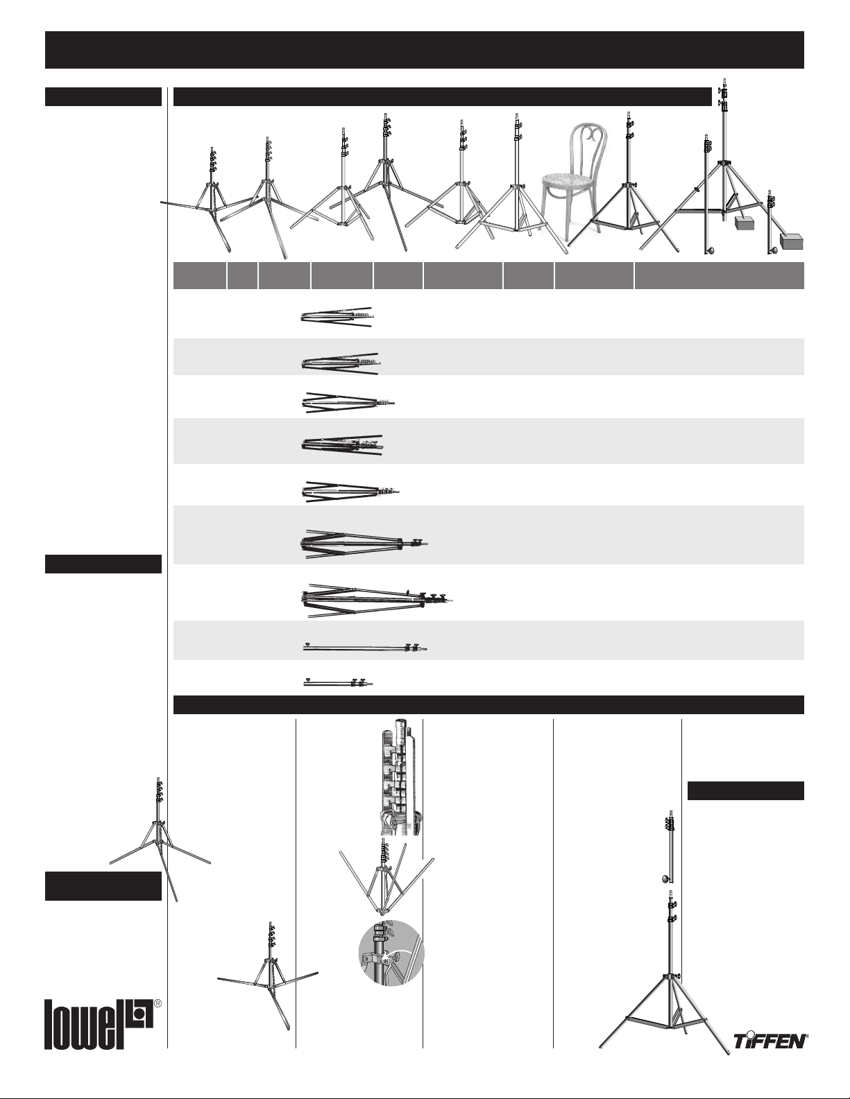
Lowel Stands
nd
a
KS
KSA
St
TO
Uni
Max.HeightCode
7'11" (2.4 m)UN-33
7
'11" (2.4 m)UN-55
9' (2.74 m)O1-33
7
' (2.2 m)UN-66
7'7" (2.3 m)DT-33
9' (2.7 m)
10.5' (3.1 m)GS
6.6' (2 m)KP
3' (91 cm)KPH
nd
a
t
s
-
Uni
Name
Uni-stand
Uni TO
Stand
Omnistand
U
ni Sr.
S
tand
KS Jr.
Stand
KS Stand
KSA Stand
Grand
Stand
Full Pole
Half Pole
Stand Use Note s
Uni, Uni TO & Uni
Sr. Stands
Extend stand legs fully as
shown for maximum stability.
When extending stand sections
to desired height, begin with
lowest section first.
Don’t fully extend any section
unless necessary. When using
with Tota/Omni, extending top
section of stand may
A
result in some loss
of stability. With Tota-light
mounted, rotate light head so
it lines up in parallel with one
of the legs for most stable balance. Fig.A The
3 Uni-stands can be set
up with its legs extended in tripod fashion or
Fig.B, set
flat on the floor
depending on the users
need for stability vs.
height.
nd
a
t
s
-
ni
Om
Folded Length Max. Base
21.5" (54.6 cm)
2
1.5" (54.6 cm) 3'7" (1.1 m)
27" (69 cm)
2
2.5" (57.2 cm.)
28" (65 cm) 3'1" (99 cm)
36" (91 cm)
43" (1.1 m)
34" (89 cm) ———
18" (46 cm) ———
Packing up
When collapsing the
Uni-stands, line up
all rotating stand
locking collars
(collars are marked
A, B, & C) with the
lowest locking collar in the center
shaft
(collar
is nonrotating &
marked D).
Slide stand legs
into notched
slots.
Tighten all
knobs.
This will
B
allow proper fit of Uni-stand
leg as it folds in against center shaft & locking collars.
Uni
D
iameter
3'7" (1.1 m)
3'1" (94 cm)
3'10" (1.2 m)
3'5" (1 m)
4'5" (1.35 m)
nd
a
St
.
Sr
M
in. Tube Diameter
Max. Tube Diameter
3/8" (.95 cm)
7
/8" (2.2 cm)
1
/2" (1.27 cm)
1" (2.54 cm)
1
/2" (1.27 cm)
7/8" (2.2 cm)
3/4" (1.9 cm)
1 1/8" (2.9 cm)
3/4" (1.9 cm)
1 1/8" (2.9 cm)
7/8" (2.2 cm)
1 1/8" (2.9 cm)
1" (2.54 cm)
1 3/8" (3.51 cm)
7/8" (2.2 cm)
1 1/8" (2.9 cm)
7/8" (2.2 cm)
1 1/8" (2.9 cm)
.
r
J
KS
Omni-stand, KS
& KS Jr. Stands
When extending stand sections to desired height, begin
with lowest section first. Don’t
fully extend any section
unless necessary. See chart
above for maximum heights.
When heights greater than 9
feet are required, use the KS
or KSA Stand with a Lowel
Full or Half Pole.
Grand Stand &
KSA Stand
The Grand Stand and KSA
Stand both feature air cushioning which allows the stand
section to descend gently,
preventing lamp damage.
All Lowel air-cushioned
stands have collars & locking
knobs that are black-finished.
Both stands have two holes in
the bottom of their legs that
nd
a
St
2.4 lbs (1.1 kg)
2.6 lbs (1.2 kg)
2.6 lbs (1.2 kg)
3
.3 lbs (1.5 kg)
3
.5 lbs (1.6 kg)
4 lbs (1.8 kg)
6.75 lbs (3 kg)
1.75 lbs (.8 kg)
1.1 lbs (.5 kg)
nd
a
St
KS
Number of Risers
Single-strut leg brace,
s
olid bar legs. 4 Risers.
S
ingle-strut leg brace,
solid bar legs. 4 Risers.
S
ingle-strut leg brace,
solid bar legs. 3 Risers.
S
ingle-strut leg brace,
solid bar legs. 3 Risers.
Single-strut leg brace,
solid bar legs. 3 Risers.
Double-strut leg brace,
tubular legs with holes
for casters or anchors.
Double-strut leg brace,
tubular legs with holes
for casters or anchors.
2 Risers (3 sections).
2 Risers (3 sections).
accept Lowel Anchors and
Casters.
The Grand Stand has an
extendible leg that can be
used to keep the stand vertical
on uneven surfaces (steps,
hills, etc.). The Grand Stand
can also be nailed to platforms when necessary.
When extending stand
sections to desired height,
begin with lowest section
first. Don’t fully extend any
section unless necessary.
Full Pole
& Half Pole
Lowel Poles can be used
to extend Lowel Grand
Stands, KS and KSA
Stands, to hand-hold
a light above crowds,
to extend lights
down from
overhead
clamps,
nd
e
a
St
Pol
l
Ful
KSA
Legs /
ViP & other small lights. Wide base for more stability,
large locking knobs. Legs lie flat to floor or in tripod
arrangement, and fold up for more compact packing.
Stud has 1/4 20 thread. Smallest folding Lowel stand.
V
iP, Tota/Omni, Rifa-lite 44 & other small lights.
S
turdier than Uni-stand, ideal for use with Tota/Omni
in GO-85 Case.
Tota & Omni lights, Rifa-lite 44 & small flags. Sturdy
& lightweight, an industry standard.
T
ota/Omni, DP Light, Rifa-lite 55 & 66, Fren-L 650,
Caselite, Scandles. Legs can lie flat to floor or in
s
tandard tripod arrangement, and fold up for more
c
ompact packing. Designed to fit into lid of Caselite.
T
ota/Omni, DP Light, Rifa-lite 55 & 66, Fren-L 650,
Caselite, Scandles. Smaller closed than KS
(for more compact packing).
D
P Light, Rifa-lite 88, Fren-L 650, Basic Boom.
Industry standard medium sized stand, taller & more
stable than KS Jr.
KSA is same as KS but with air-cushioned riser
2 Risers.
sections, black castings & knobs.
Variflector, larger/heavier lights, Big Boom.
Extra wide base, one leg extends longer for use
on uneven ground, gray anodized stand with
2 Risers.
air-cushioned sections & direct screw clamping.
Extend KS, Grand Stand. Forms: boom, background
support, rigs. Updated with extra section & additional
length for added security when used at original length.
Same as Full Pole.
Recommended Uses & NotesWeight
S
tud has 1/4 20 screw thread.
and to form booms, rigs
and various mounting and
adjusting devices.
Problems, info, etc.
Lowel equipment and kits are sold
through authorized Lowel Dealers
and, in some countries, Authorized
Lowel Distributors. Repairs, problems, suggestions, and requests
for brochures, instructions, parts
lists may be handled by your
authorized Lowel Dealer
(Distributor) or directly with
Lowel. Electrical repairs should be
made only by Lowel or a qualified
electrician.
ver: 5.1 © 2006 Lowel-Light Mfg., Inc.
984
Grand Stand
Half Pole
Page 2
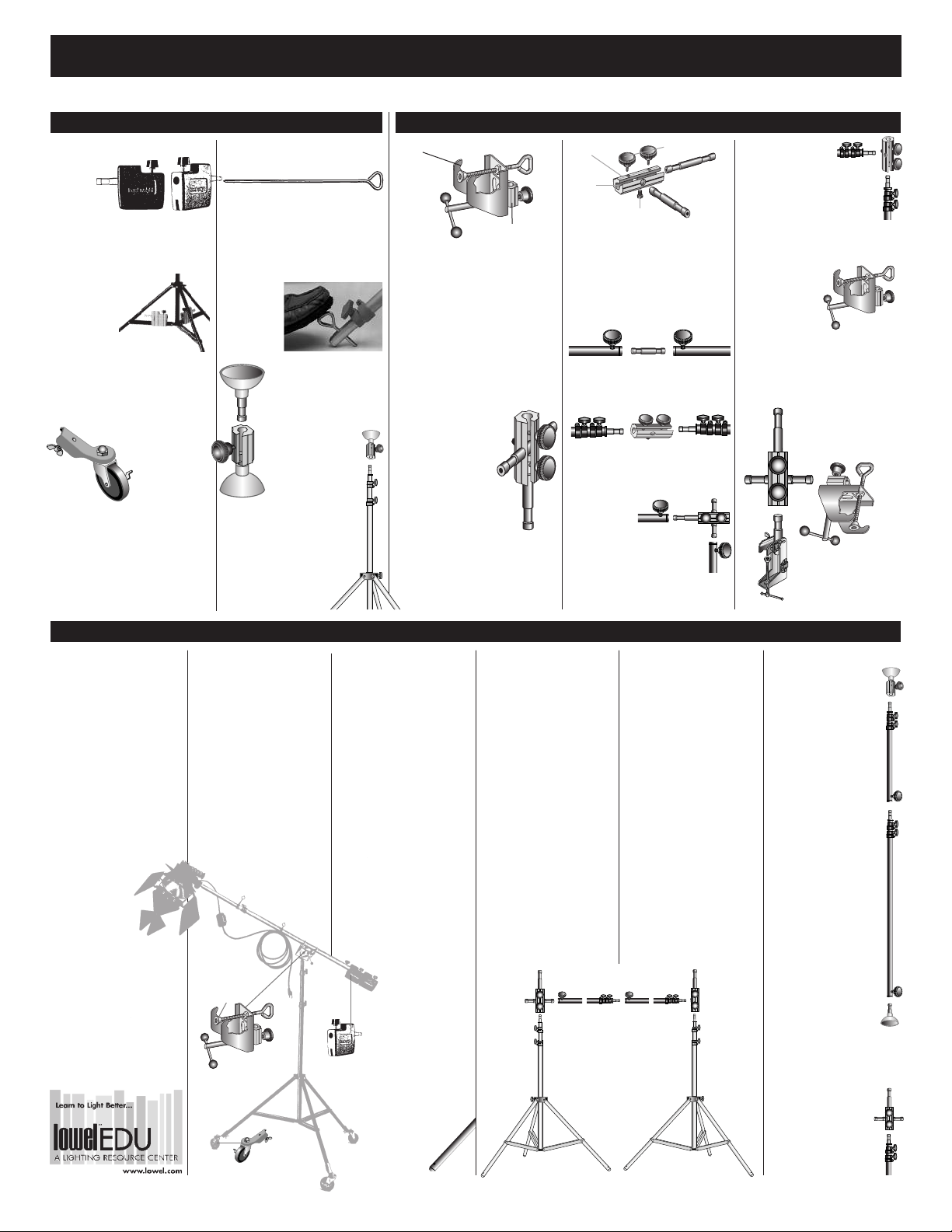
Lowel Stand Accessorie s Instructions
Stand Accessories Interlink System
Lowel Weight
Code:
LW
Weight: 4.25
lbs (1.93 kg)
Modular counterweight. A 5/8" (1.59
cm) stud locks on female end of
Lowel poles to counterbalance
booms. Two or
three weights
fit together.
For additional
ballast, tighten
knob securely
to hold weights together. Slots in
bottom fit on stand leg struts to
increase stability.
Lowel Casters (3)
Code: LC
Weight:
2.4 lbs (1.09 kg)
Lockable wheels
fit leg holes on
KS, KSA and Grand Stands.
Especially helpful for booms and studio lighting. (Set of 3). Unscrew
wing-nut bolt, place stud thru leg
hole, attach wing-nut & tighten.
Lowel Anchors
Code: LA (Set of 4)
Ground spikes fit through leg holes
in KS, KSA and Grand stands to
increase stability when used on
grass, sand etc. and are recommended especially when reflectors are
used. A hand, foot or rock can be
used to force
the Anchor
through the
holes in the
legs and into
the ground.
Ceiling Link
Code: KCL
A
Set includes one male A,
one female B.
Holds one or more
lights with Lowel
Clamps and Grips.
The female half
B
attached to a stand to secure
it against a ceiling.
Rubber and aluminum components lock onto ends of Lowel
poles. Compression secures
rig in place to make floor
to ceiling poles.
of the set can be
V groove Locking knob
Tilt control
Lowel Grip
Code: KG
This versatile clamp attaches to
stands, poles, pipes, 2" x 4"s etc. to
support lights with Interlink; makes a
boom out of Stand and Pole; works
with Space-clamp, Maxa-mount,
Frame-up. Tilts 180°; pans 360° and
locks securely.
Lowel Interlink
Code: K1-10
Interconnects various
Lowel components. Adds
B
multiple mounting positions; joins two Lowel
Poles (male or female
ends) in a straight line or at
right angles (90°). Both 5/8"
(16mm) studs are removable
and have a 1/4-20 threaded
hole to simplify mounting accessories with 1/4-20 bolts.
Stand fitting
Body
Cross
hole
Use 7/16' wrench
The three main parts of the
Interlink can be used together
or separately.
The following are a few of the various Interlink combinations.
Stud can connect the female ends
of two Lowel Poles (or other
components).
Body can interlock two male ends of
Lowel Poles (or other components
such as clamps).
Full Interlink
can connect the
female ends of Lowel
Poles (or other components)
at 90° (right) angle.
Identical studs
1/4-20
threaded
hole
Body can connect
the male end of
Poles, or a Stand and Pole, to
form a 90° (right) angle.
Interlink or just the stud
can be locked into the 5/8" female
connection on a Lowel Grip and the
assembly can then be clamped onto
any part of any
stand, pipe, 2x4 etc.
A light or another
Grip can be
attached to the stud.
Interlink can be locked onto a Totaclamp A, Lowel Grip B, or various
accessories.
B
A
Booms, Supports & Rigs
The following booms are
assembled from components
described on this sheet. The
same components can be used
individually and in other combinations, as required. The
equipment may also be
extended or adapted using
additional Lowel components
(see "Stands, Poles, Booms,
Rigs" sections at lowel.com or
in Lowel Catalog). Also, see
"Warnings" on front page.
Tighten all knobs
adequately with
hand leverage only.
Never raise stand or
adjust boom while
people are under it.
Basic Boom
Code: SP-91
1 KSA Stand (KSA)
1 Grip (KG)
1 Full Pole (KP)
2 Lowel Weights (LW)
1 Set (3) Lowel Casters (LC)
1 Pkg (10) Cable Clips (K4CC)
Big Boom
Code: SP-90
1 Grand Stand (GS)
1 Grip (KG)
1 Full Pole (KP)
2 Lowel Weights (LW)
1 Set (3) Lowel Casters (LC)
1 Pkg (10) Cable Clips (K4CC)
D1
D2
Putting together
a Boom
1 Assemble casters A to
stand B through holes in
end of legs and tighten
wing nuts.
3 Lock Grip D onto stud and
lock tilt control D1,
at convenient angle, using
knob with balls on ends.
4 Extend pole E half way;
insert it into V portion of
Grip D2; cradle and tighten
lock knob.
5 Lock one weight F into
female end of pole.
6 Lock light or other
equipment onto 5/8” male
E
D
stud on boom.
7 Lock in second weight.
8 Adjust for balance using
extension on pole
or move entire Pole
within Grip.
F
Background
Support
Code: SP-93
2 KS Stands (KS)
2 Interlinks (K1-10)
2 Full Poles (KP)
This versatile rig supports
seamless paper rolls, black
velour, other material, adjusts
from 32" (81.3 cm) to 10’
(3.05 m) wide. Accepts two
back lights without additional
clamps; components can be
used separately as well.
1 Attach Interlink A to one
stand, Interlink B to other
stand.
2 Remove cross stud from
Interlink B by loosening
retaining bolt with 7/16"
wrench or Vise-grip.
AC D
3 If seamless paper is to be
used, insert pole or two
interlocked poles C and
D (or pipes if preferred)
through roll. (Some
small diameter cardboard
tubes may necessitate
substituting 1/4-20 bolts
for knobs on poles.)
4 Lock poles to Interlinks.
Elevate both stands
simultaneously,
if possible.
Other materials suitable for
background or blocking or
diffusing light may be
clamped or taped to poles.
Lights may be mounted to
studs projecting from
Interlinks and will be well
positioned for backlight
sources.
B
Floor-toCeiling Pole
1 Assemble required
number of poles H
and/or half poles I
to reach vertical span.
2 Lock on ceiling link
F and G at opposite
ends.
3 To hold securely,
cups on ceiling link
must be flattened
completely against
floor and ceiling.
This is most easily
done by pressing
down with a foot
while extending
a pole section with
one hand and locking
collar clamp on
pole with the
other hand.
Lights that are not too
heavy can be attached
with suitable clamps
such as the Tota-clamp.
4 An Interlink J
inserted between pole
and top ceiling link
can also support
a light.
F
I
H
G
J
Caution: Test for safety of
A
B
installation and never
use poles horizontally.
 Loading...