

Page 1
Instructions
Warnings 2
Setup & Lamp Installation 3
Rear Panel 3
Mounting 4
Accessories 4-6
Warranty, Problems, Repairs & Information 7
®
Page 2
Warnings
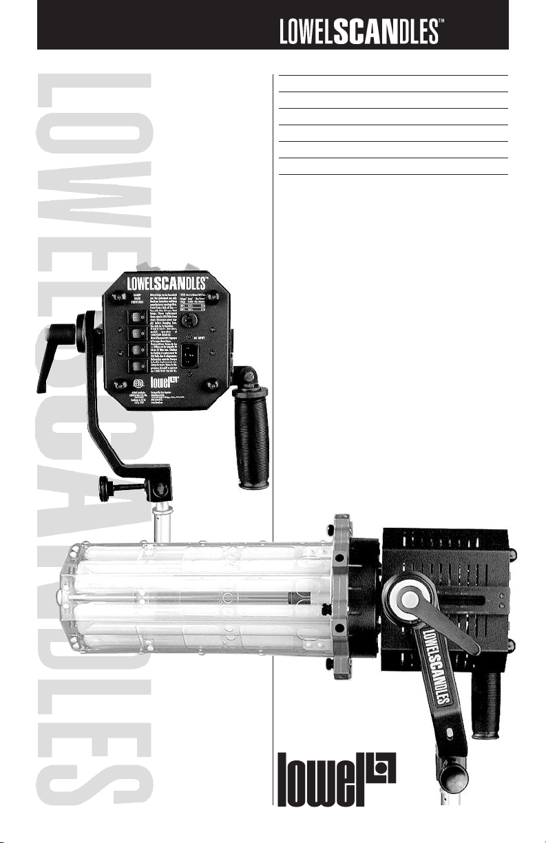
The LowelScandles™ fluorescent
system is a professional lighting
system. Read these instructions
and lamp manufacturers warnings before operating.
n Don’t leave fixture unattended.
n Not for household use.
Use only for photographic
lighting (video & film imaging).
n Do not exceed maximum rated
wattage for unit.
n Use maximum 24 Watt lamps.
n Always unplug fixture
before relamping.
n Always unplug unit before
changing fuse.
n Make sure lamps are securely
seated in lamp socket.
n Do not use near standing water.
n Do not open unit,
no user serviceable parts inside.
n Internal ballasts produce
high start-up voltage.
n Never bypass plug’s
ground pin.
n Do not interfere with unit’s
ventilation.
n Make sure clamp is tightened
at yoke.
n Always use Safety Cables,
when attaching to overhead pipes
or grids.
n Do not attempt to open unit,
no user serviceable parts inside.
n Always use with supplied
Lowel AC Cable.
n Do not use the ballasts in
ambient [room] temperature greater
than 105°F as this will
void their warranty.
n This is a portable location
light, It complies with UL 1573
for still photographic lights when
used with the supplied T1-80 cable.
For use as a portable stage lighting
unit use with Lowel T1-808 10'
unswitched cable rated for ‘hard
service’.
Fluorescent
Warnings
n Avoid looking directly at the
tubes for extended periods of time.
n Make sure lamps are well
sealed.
n Fluorescent tubes contain
highly poisonous mercury.
n In the event of lamp breakage,
avoid contact with broken pieces,
and dispose of properly.
n Read lamp manufacturers
information fully.
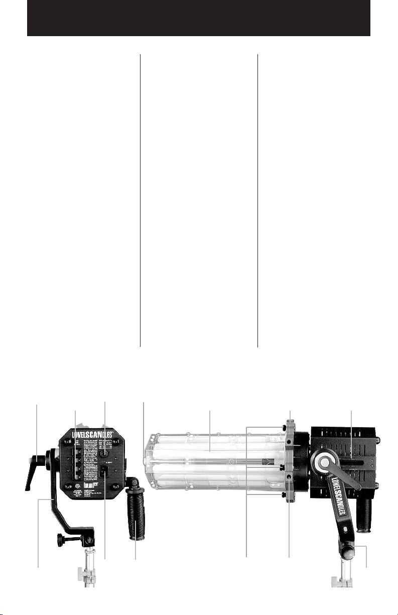
Locking
Handle
Rotating
1/2 Yoke
Lamp
Pair
Switches
Fuse
Holder
AC
Cable
Input
Lamp Shield
Locking Nuts
Swing
Down
Handle
Lamps surrounded
by Polycarbonate
Lamp Shield
Front Accessory
Retaining
Screws
2
Universal Rotating
Speed Ring and Front
Accessory Holder
Softbox
Mounting
Holes
Sliding
Stage
Stand
Fitting
Page 3
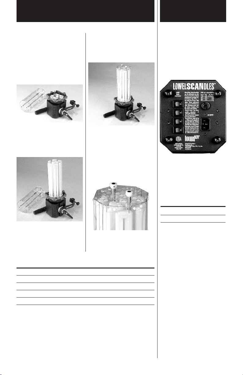
Setup & Lamp Installation
Rear Panel
n Loosen the side yoke locking
handle so that the yoke can be easily
positioned out of the way for the
following procedure.
n Place the fixture on its 4
small support feet so that the sockets
face up, making sure that the AC Cable
is not connected.
n Gently snap the 8 fluorescent
lamps into the cluster of sockets on
the front of the fixture. Start with the
center lamps.
Note: The procedure is the same
whether installing 12" or 8" lamps.
n Position the Polycarbonite
Lamp Shield over the installed lamps
so that the holes in the metal plate end
of the shield line up with the ends of
the lamps.
n Gently slide the shield down
over the lamps until it completely
covers the lamps. Carefully tighten the
2 nylon Locking Nuts A on the front of
the shield. This tightens the threaded
ends of the shafts at the fixture body
to securely hold the shield and lamps
in place.
A
A
n The AC power cord attaches to the
socket on the rear panel and contains a
master power switch.
Lamp Switches
There are 4 lamp switches A,
each controlling a pair of lamps.
By turning one or more pairs of lamps
off, you can vary the output of the light.
Remember that there is also a master
power switch in the supplied
AC Cable.
A
A
A
A
B
Fuse Replacement
To open the fuse cover B, first make
sure that power has been disconnected
to the fixture. Use a small flathead
screwdriver to remove and replace fuse
if needed.
Fuse Use 5 x 20mm / 250V fuse
Voltage Fuse Max. Power
120 V 2.5 A 2.2 A
230 V 1.6 A 1.4 A
Lamp chart
Lowel Code Wattage Size Description Color temperature
LSF-24DA 24W 12" Dulux L 24 W/12 5300°k (Daylight)
LSF-24TU 24W 12" Dulux L 24 W/32 3000°k (Tungsten)
LSF-18DA 18W 8" Dulux L 18 W/12 5300°k (Daylight)
LSF-18TU 18W 8" Dulux L 18 W/32 3000°k (Tungsten)
Film Use
If using Scandles with conventional film, initial experiments suggest a minus 1/4
or 1/2 green filtration for film exposures.
3
Page 4

Mounting Accessories
Mounting
on stand
n Holding the fixture
with lamps & shield
installed, carefully position the
stand fitting end of the yoke arm
on the 5/8" stud of the stand.
n Tighten the locking arm to
prevent the light from falling
forward. Make sure to align one
of the stand legs directly underneath
the lamps for best stability. Add
weights to the stand base for safety if
needed.
n Recommended Lowel Stands:
KS or larger for best stability,
however Uni Sr., and KS Jr. can
be used for more portability.
Mounting on boom
n Rotate the yoke counter-clockwise
to position it for attachment to a 5/8"
stud on the end of a boom using either
of the stand fitting holes. Experiment to
find the position that best suits your
purpose.
1
2
Mounting Yoke
The yoke of the LowelScandles
light is designed to allow maximum versatility when mounting
the fixture.
C
A
A Yoke
B Locking handle
C Sliding stage adjustment
D Stand fitting
n The yoke can rotate approximately
300 degrees, and has 2 additional 5/8"
stud mounting holes, allowing it to
attach from different angles.
n The yoke arm also has a hole for
attaching safety cables which must be
used whenever hanging the fixture
from boom or rail.
n The locking handle can be loos-
ened to allow the fixture to slide back
& forth. This is useful to reposition the
light’s center of gravity, making it more
stable on the stand, especially when
attaching front accessories which can
cause the balance to shift.
D
Attaching
Accessories
B
B
B
B
A Universal Rotating Speed Ring
and Front Accessory Holder
B Front Accessory Retaining Screws
C Softbox Mounting Holes / Screw
threaded accessory holes.
The LowelScandles light has a number
of front attachment accessories which
can be used to help vary the output
and quality of the light. They attach to
the installed Universal Rotating Speed
Ring, either by using the 4 retaining
screws on the front of the ring, or the 6
softbox mounting holes on the side of
the ring. In addition, there are 2 screw
threaded holes on the side of the ring
(1/4-20, and 3/8-16) for additional
options).
C
A
C
n Whenever mounting fixture over-
head, always attach safety cables
between the fixture and the rail using
the hole in the yoke.
4
Page 5

Accessories
Collapsible Cone &
Front Diffuser
n The sections of the cone are
made of clear plastic and come with
installed reflective material, which
should be suitable for most lighting
purposes. Each section opens to allow
color gels, diffusion or other reflective
materials to be used for special purpose lighting effects.
n Assemble the Collapsible Cone
by zipping the 3 sections together.
n To attach the cone & ring
to the front of the rotating speed ring,
place the fixture with lamps & shield
installed on a table, facing up so that
it rests on its 4 rear panel support
feet, or securely on a stand, facing
straight up.
n Remove the 4 plastic retaining
nuts from the screw posts on the speed
ring and carefully place the cone over
the lamps so that its metal ring rests in
Hard Cone Reflector
n The Hard Cone Reflector
is designed for studio use. It is not
collapsible. Attach the Hard Cone
Reflector using the same procedure
as the Collapsible Cone.
n Place the fixture, with lamps
& shield installed, on a table facing
up so that it rests on its 4 rear panel
support feet.
n Attach the narrow end
of the cone to the Mounting Ring by
lining up the 3 snaps.
the recess of the ring. Replace the 4
plastic nuts and tighten securely.
If you want additional softness, attach
the front diffuser to the front of the
cone reflector by collapsing the cone
slightly to get the elastic of the diffuser
over it. Note: diffuser reduces output
by approximately 50%.
5
n Remove the 4 plastic retaining
nuts from the screw posts on the speed
ring and carefully slide the reflector
over the lamps so that its metal ring
rests in the recess of the ring.
n Replace the 4 plastic nuts and
tighten securely. You can attach the
Lowel Fin-S clip adjustable barndoor
to the rim of the reflector for additional
light control.
Page 6

Accessories
Chimera-style
Softboxes &
Lanterns
B
C
A
B
C
B
A Universal Rotating Speed Ring and Front Accessory Holder
B Front Accessory Retaining Screws
C Softbox Mounting Holes / Screw threaded accessory holes
n Universal Rotating Speed Ring
allows attachment of all current
professional softboxes & chinese-style
lanterns.
n There are 8 evenly spaced blocks
with mounting holes on the ring. 6
of these are for softbox attachment.
There are also 2 screw-threaded
holes on the ring for additional
options. These holes have their size
inscribed on them (1/4-20 or 3/8-
16).
6
n Assemble lanterns or softboxes
per manufacturers instructions and
attach to the speed ring by flexing
the rods into the predetermined
holes.
n Once installed, rotate the speed
ring to position the softbox or
lantern for desired use.
Page 7

Warranty, Problems, Repairs & Information
Lowel-Light Manufacturing, Inc.
(Lowel) warrants that its products
(other than those products which by
their nature are consumed), under
normal use in accordance with operating instructions, will perform to the
specifications published by Lowel at
the time of purchase, for the following
periods, from the date of purchase by
the consumer:
Five Years – With respect to stands
and poles.
Two Years – With respect to lighting
fixtures only.
One Year – With respect to all other
products (other than those products
which by their nature are consumed).
Lowel warrants that its products which
by their nature are consumed, such as
gels and Gaffer-tape, under normal use
in accordance with instructions for use,
will perform to the specifications published by Lowel at the time of purchase. In the event of a defect reported
by the consumer within the applicable
time period, if any, Lowel will, at its
option, replace or repair the defective
merchandise at no charge to the consumer for either parts or labor.
The consumer should be aware that
Lowel does not manufacture lamps and
therefore makes no warranty with
respect to these products. However, the
warranty of the manufacturer of such
products, if any, shall be assigned to
the consumer if permitted by such
manufacturer.
Repairs and Replacement Parts
If Lowel shall; upon the request of the
consumer, install, alter, modify, or
repair any Lowel product, or component thereof, then Lowel shall warrant
such product or component from the
date of such installation, alteration,
modification, or repair, in accordance
with the specifications published by
Lowel at such date, for the applicable
time period, if any, for such product or
component, and under the conditions,
limitations, and procedures set forth in
this warranty. Lowel will not be
responsible for any loss, damage or
expense of any kind resulting from the
installation, alteration, modification, or
repair of any Lowel product by any
entity other than Lowel.
Procedure
In order to make a claim under the
above warranty, the consumer must,
within the applicable time period, if
any, bring or send, postage paid, the
defective product and proof of purchase (or, if applicable, proof of installation, alteration, modification, or
repair by Lowel) to the consumer’s
Lowel dealer or to the Lowel factory at
90 Oser Avenue, Hauppauge, N.Y.
11788
Warranty Exclusions
THE WARRANTY SET FORTH ABOVE
IS THE ONLY WARRANTY MADE BY
LOWEL WITH RESPECT TO
LOWEL PRODUCTS AND LOWEL
DISCLAIMS ALL WARRANTIES OF
MERCHANTABILITY AND FITNESS
FOR A PARTICULAR PURPOSE AND
ANY LIABILITY WITH RESPECT TO
SAME WHETHER IN CONTRACT,
TORT OR OTHERWISE. IN NO EVENT
SHALL LOWEL BE LIABLE FOR LOST
PROFITS, OR ANY CONSEQUENTIAL
OR INCIDENTAL DAMAGES
INCURRED BY THE CONSUMER.
Some states do not allow limitations
on how long an implied warranty lasts,
and some states do not allow the
exclusion or limitation of incidental or
consequential damages, so the above
limitation may not apply to you.
General
This warranty gives you specific legal
rights, and you may also have other
rights which vary from state to state.
Repairs, problems, suggestions
and requests for brochures/catalogs,
instructions and parts lists can be
handled through your Authorized
Lowel Dealer / Distributor or directly
through Lowel. Electrical repairs
should be made only by Lowel or by a
qualified electrician.
For further
information,
contact us:
Lowel-Light Manufacturing, Inc.
90 Oser Avenue
Hauppauge, N.Y. 11788
Call: 800 645-2522
e-mail: info@lowel.com
web: www.lowel.com
7
Page 8

DP Light Instructions DP Light Instructions
LowelScandles is a trademark of
Lowel-Light Manufacturing, Inc.
LowelScandles was designed
by Gary Regester
© 2010 Lowel-Light Manufacturing, Inc. 111
Lowel-Light Manufacturing, Inc.
90 Oser Avenue, Hauppauge, N.Y. 11788
Call: 800 645-2522
e-mail info@lowel.com
www.lowel.com
®
 Loading...