

Page 1

Model 200 Instructions
Warnings
Lowel Prime™ LED equipment is a professional lighting system. Read these
instructions, as well as accessory instructions and applicable warnings before
operating.
n Do not leave fixture unattended.
For fixed (stationary) use in studio's, theaters,
and similar locations.
n Not for household use. Use only for
photographic lighting (video & film imaging).
n Always unplug unit before
changing fuse.
n Do not use near standing water.
n Never bypass plug’s ground pin.
n Do not interfere with unit’s ventilation.
n Do not operate unit with
Accessory Barndoors closed.
n Make sure clamp is tightened at yoke.
n Always use Safety Cable,
when attaching to overhead pipes or grids.
n Always use with supplied Lowel
AC Cable.
LED Warnings
n Avoid looking directly at the LED's
for extended periods of time.
n LED's take time to reach standard
operating output level, and frequently have
slightly higher output during the first 1/2 hr,
when powered up.
Mounting the Fixture
On Lighting Rail:
Attach clamp tightly to yoke of fixture, according
to clamp mfrs. instructions. Hang clamp on pipe
or grid and tighten the large screw so that the
clamp and fixture are securely mounted. Do not
loosen bolt attaching clamp to fixture, to position
light. Attach safety cable between the fixture and
the rail for necessary security.
On Stand:
There are 2 options for stand mounting of the fixture, using the 5/8" female stand fitting or using
the optional Male Stud. Choose proper size stand
for fixture. For all models, the Lowel Grand Stand
or larger is preferred, however the following stands
may also be used. Always use sufficient stabilizing
weight on stand base.
Model Lowel Stand
200 KS or KSA
400 KSA
600 Grand Stand*
*Do not use with top stage extended
Each fixture comes with:
n Gel Frame
n Safety Cable
n Standard C Clamp
yoke hanging mount device
n Female 5/8" Stand Fitting
n 2 Standard 120v AC power cables with
male Edison connectors (or appropriate international CE approved plug). For 120v, use the
unswitched T1-808 AC cable for C-clamp grid, or
pipe hung 'studio' use. Use T1-80 switched AC
Cable for use on stand or boom where access to
fixture power switch may be out of reach.
YokeControl
Clamp
Tilt Lock
Handle
Accessories
Door
Brake
Disk
Control
Handle
Female 5/8" Stand-fitting:
For use on stand only. Allows mounting the fixture
on 5/8" male stand stud. Make sure the stand
is large enough to support the weight of the
fixture while maintaining good balance at the
desired height. Attach the female stand-fitting
tightly to the yoke and rotate yoke so it is on the
underside of the fixture. Tighten yoke, clamp locking lever, and place female stand-fitting over
stand, making sure that its locking screw is loosened enough to allow the fitting to completely fit
over the 5/8" stand stud. Tighten knob, making
sure its screw is under the safety cut of the stand
fitting stud. Add additional weight to base of stand
for increased stability.
Male Stud (Code, FLS-MS):
For use of fixture with Matthews style stands that
have a female cup instead of a male stud. Attach
the optional Male Stud in the same manner as
described above for Female 5/8" Stand Fitting,
again rotating the yoke to the underside of the fixture and tightening yoke clamp. Carefully place
Male Stud into female cup on stand top and tighten. Add additional weight to stand base for
increased stability.
Specs & Performance: Daylight & Tungsten Models
15.5" (39.3 cm)
14.9" (38 cm)
17.7" (44.9 cm)
Daylight Model
Code: PRM-200DA
Color Temperature: 5600˚K
Color Rendering Index: 91+
Weight: 13.5 lbs (6 kg)
Tungsten Model
Code: PRM-200TU
Color Temperature: 3300˚K
Color Rendering Index: 91+
Weight: 13.5 lbs (6 kg)
3.5" (8.9 cm)
Lowel Prime LED is not a color mixing
LED system. There are dedicated
Tungsten and Daylight color models.
However, for optimal color balance of light output, tungsten color models have a small qty of
daylight (C) LEDs, and daylight color models
have a small qty of tungsten (W) LEDs, integrated into the front panels.
The color temperature of each fixture can be
changed slightly (aprox 100-200 degrees K) by
changing settings in the in DMX mode. This may
help critical color balance to other light sources.
See Changing DMX Operation Mode, in the SET
Function section of this instruction sheet.
Beam Angles:
points at which intensity
drops to 50% of maximum.
Foot Candle readings taken with Tungsten
color model, at center of beam, using a Minolta
CL-200 meter.
Fuses & Power Consumption
Note - Most electrical equipment briefly consumes a higher amount of electrical current during startup (ignition). Consult the below chart to confirm that your electrical wiring is sufficient for the fixtures
used. All fuses must be rated at 250VAC. Lowel Prime LED's auto-set from 90-240 VAC.
110V 240V
Model Fuse Nominal Peak Nominal Peak
200 3 A / 250 V 0.714 A 0.97 A 0.403 A 0.61 A
PRIME LED Model 200 Consumes 85 Watts
Current Ignition Current Ignition
Current Current
Problems, repairs & info
Repairs, problems, suggestions
and requests for brochures/catalogs,
instructions and parts lists can be
handled through your Authorized Lowel
Dealer/Distributor or directly through
Lowel. Electrical repairs should
be made only by Lowel or by
a qualified electrician.
Lowel Prime LED equipment is a product of the
ongoing collaborative relationship between
Lowel-Light and Fluotec, Mexico
Clamp
Female 5/8"
Stand Fitting
Safety
Cable
Male Stud
(optional)
Lowel-Light Manufacturing, Inc.
90 Oser Avenue, Hauppauge, N.Y. 11788
Call: 800 645-2522 or 631-273-2500
Fax: 631-273-2557
e-mail info@lowel.com
www.lowel.com
ver. 1.3 © Lowel-Light Mfg., Inc 2011
281
Page 2
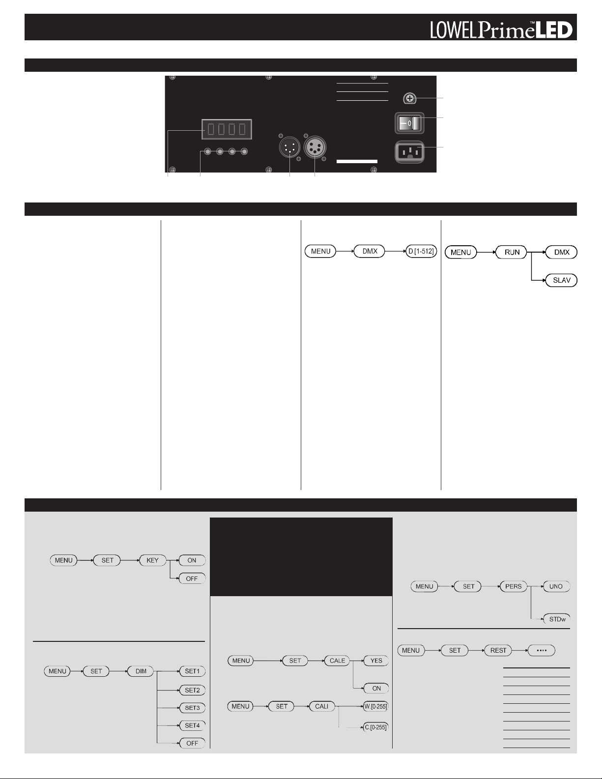
Lowel Prime™LED Control Panel
MENU ENTERUPDOWNDOWNDOWN
DMX IN DMX OUT
DOWN
LOWEL
LED
T
UNGSTEN
Pr ime
200
T
UNGSTEN
ON OFF
FUSE 3A
POWER IN
Serial Number
MODE L: PRM- 200T U
I
nput Nominal Peak
Voltage Current Cu rrent Fuse
120VAC 0. 714A 0.97A 3A/250V (USA /Canada)
220VAC 0.403A 0.610A 3A/250V (Worldwide)
WARNING:
Not f or r esident ial use . For
professional use only. Rea d our inst ructions
and la mp m anufac turer’ s wa rnings first.
Disconnect f rom main s upply bef ore servi cing.
AVERTISSE MENT:
Impr opr e à l’us age
domestique . Empla cements mouillés .
CAUTION:
Risk of fi re - Use repl acement
fuses ra ted a t 3.00 Amps and 250 Volts. Use
only in dr y locat ions. Di sconnect Power Befo re
Changing Fus e.
CAUTION:
Employer des fusi bles de rech ange
de 3.00 Amps et 250 Volts. Emplacements secs.
Débrancher avant de cha nger le fusible.
AMPERAGE:
0.97 Amps at 120 Volt s.
0.610 Amps at 220Volts
A
C POWER INPUT
USA/Canada: 110-120V, 60 Hz, 82W
W
orldwide: 100-240 V, 60Hz, 82 W
Cable Diameter: 6.5~8mm
Power Cable: 18~16AWG
Data Cable: 3 pi n shielded
Light Source: LE D
™
Manual & DMX Operation
Controlling Lowel
Prime LED
The fixtures of the Lowel Prime LED Series are all
dimmable models, which can be controlled either
manually on the fixture or remotely via a console
with DMX-512 protocol.
Fuse
AC Power Switch
To operate the Control Panel, first familiarize
yourself with the placement and functions of
the controls.
LED
Display
Rear Panel Connections & Functions
Power In
This IEC connector accepts the AC cable. The fixture will auto-set itself from 90-240 VAC. Use the
proper cable for the country of use.
AC Power Switch
Turning on the AC Power switch causes the fixture to light at whatever dimming level it was at
when last powered down (factory shipped at
100%). The unit will retain its previous dimming
level even if unplugged.
Fuse
Always power down & unplug the fixture before
changing its fuse. Open the fuse holder with a
phillips head screwdriver to replace the fuse.
Lowel Prime 400 LED's use fuses rated at 3
Amps and 250 Volts.
DMX In/Out Connectors
There are two 4 pin XLR style DMX connectors,
labeled IN and OUT. In a DMX chain, remember
that the last fixture in the chain needs a DMX
Terminator plugged into its DMX Out connector.
LED Window
& Function Buttons
The LED window shows the status of choices
made with the function buttons beneath it.
MENU Repeated pressing of the MENU Key
scrolls the unit thru its sub-menu list (DIMM,
RUN, DMX, SET).
ENTER To select a menu or to confirm the values
selected.
UP Button To increase a value, 1 step at a time,
or scroll up thru a sub-menu.
DOWN Button To decrease a value, 1 step at a
time, or scroll down thru a sub-menu.
Manual Dimming
0% to 100%
Lowel Prime fixtures can be dimmed manually on
the rear of the unit, or by DMX console.
To manually dim the light to a desired level, press
the MENU button until you see DIMM, then Press
ENTER. Use the Up & Down buttons to set dimming level from 1-100. Powering the fixture down
keeps its dimming level set, so it will return to
that level the next time it is turned on.
Function Buttons:
Menu / Enter / Up / Down
DMXInDMX
Out
DMX Addressing
& Dimming
DMX-512 protocol allows you to assign one of
512 possible control addresses to the fixture.
Multiple fixtures must be connected to each
other, daisy chain style, using DMX cables, with
the DMX OUT on the console connected to the
first fixture's DMX IN connector. The DMX OUT
connector of the 1st fixture is then connected to
the DMX IN connector of the second fixture, and
so on, until all fixtures are connected. The last
fixture needs a DMX Terminator plugged into its
DMX OUT connector.
When the fixture is receiving a valid DMX signal,
a blinking red dot is visible in the lower right corner of LED Window.
To ADDRESS a fixture, scroll the MENU list to
DMX, and hit ENTER. Next, scroll to the DMX
address number you want for the fixture.
Pressing ENTER again and hitting MENU sets
fixture to that address and enables DMX dimming. After addressing the whole chain, fixtures
may be controlled alone or in a group, from the
DMX console. Manual dimming on each unit is
inoperative during DMX operation.
AC Input
Slave Controlling Fixtures
Without Console
Multiple fixtures, connected with DMX cables as
described above, can all be controlled as one by
using the Slave function. This means they will all
dim up or down together, controlled by the first
fixture in the chain (not by a DMX console).
On the first fixture in the chain, in MENU, select
RUN and hit ENTER. Using the up/down buttons shows 2 choices, DMX and SLAV. Select
DMX for the first fixture in the chain and SLAV
for the rest.
The SET Function
Locking / Unlocking User Control
This tamper proof security ability allows the user to disable the
function buttons, locking out the fixture from manual control.
It can be restored by use of a keycode password.
n To Lock (Disable Use):
Choose ON, and press ENTER. LED display window
will show only a single red dot. NOTE: Lock takes aprox.
10 seconds to engage.
n To Unlock (Enable Use): Press these buttons in the following
order: MENU + UP + DOWN + UP + DOWN + ENTER. Then
press: MENU + SET + KEY+ OFF + ENTER.
Accessing Stored Alternate
Dimming Curves
To vary the rate of dimming when using a DMX
console, there are four factory installed dimming
behavior curves. They are accessible thru
the SET menu. Press ENTER to advance
at each step.
The fixture ships preset to dimming curve
number 4.
Choosing SET allows access to functions that most users will
not ever need access to. They include locking access to fixture controls, using stored alternate dimming curves, mfrs
calibration settings, as well as restoring the fixture to all of
its original (pre-calibration) settings. Always hit ENTER to
advance thru the Menu choices.
IMPORTANT – If you accidentally wander in any of the SET
sub-menu's, hit MENU button to return to the main Menu.
Enabling / Adjusting Factory Calibration
It is not recommended to make adjustments to the Calibration settings. They are used by the factory to calibrate the fixture to established specifications. Calibration levels for warm and cool LED sets
are listed on a label found inside the Front Accessories door for use
in restoring the fixture to Mfrs. Spec. after Resetting it.
A.
Calibration must first be enabled, using sequence A,
and choosing YES. (Default setting is NO).
B.
Use sequence B to alternate between the cool
and the warm color LED sets, adjusting levels.
Set by hitting ENTER.
Changing DMX Operation Mode
This sequence allows the daylight & tungsten LEDs to be separated,
and given DMX addresses, for separate control.
n UNO - the fixture operates as 1 address.
n STDw - creates separate DMX channels for each color.
Second color gets next numerical DMX address.
Note: When using this Mode, make sure the next
numerical DMX address is available for the second
color's address.
Resetting the System
Reset the fixture to its factory default
settings, by following the above button
sequence. See the chart for default
values.
The '4 dots' sequence is as follows:
UP + DOWN + UP + DOWN +
ENTER. UP + DOWN + UP +
DOWN + ENTER. LED says OK when
fixture is reset
MENU DEFAULT VALUE
DIMM D.100
RUN DMX
DMX D.001
SET -> KEY OFF
SET -> DIM DIM4
SET -> CALE NO
SET -> CALI W.255
C.255
SET -> PERS UNO
 Loading...