

Page 1
Lowel i & id-light Instructions
Warnings
The Lowel i & id-lights are professional DC powered lighting fixtures.
Read these instructions and lamp manufacturer’s warnings before operating.
n Not for house hold use, use only
for film, video or imaging purposes.
n The units use lamps of several
different voltages. Make certain that power
source voltage matches lamp voltage.
Example: never connect a 12 volt lamp
to a 30 volt source.
n Do not use near standing water,
or in rain.
n Units such as this emit
considerable light and heat, and if not
properly used, could be dangerous.
n Lights should not be positioned
extremely close to people. Ultraviolet light ray
emissions can cause damage to the eyes and
reddening of the skin. The likelihood of either
occurring is increased with length of exposure, focus intensity and proximity. Therefore,
lights should be kept away from people.
n Avoid aiming the light at, or placing
too close to, people, delicate objects or
flammable materials.
n Do not interfere with ventilation
by covering the lights in any way.
n For proper ventilation, do not tilt
down beyond 45 degrees or operate sideways.
Yes
No
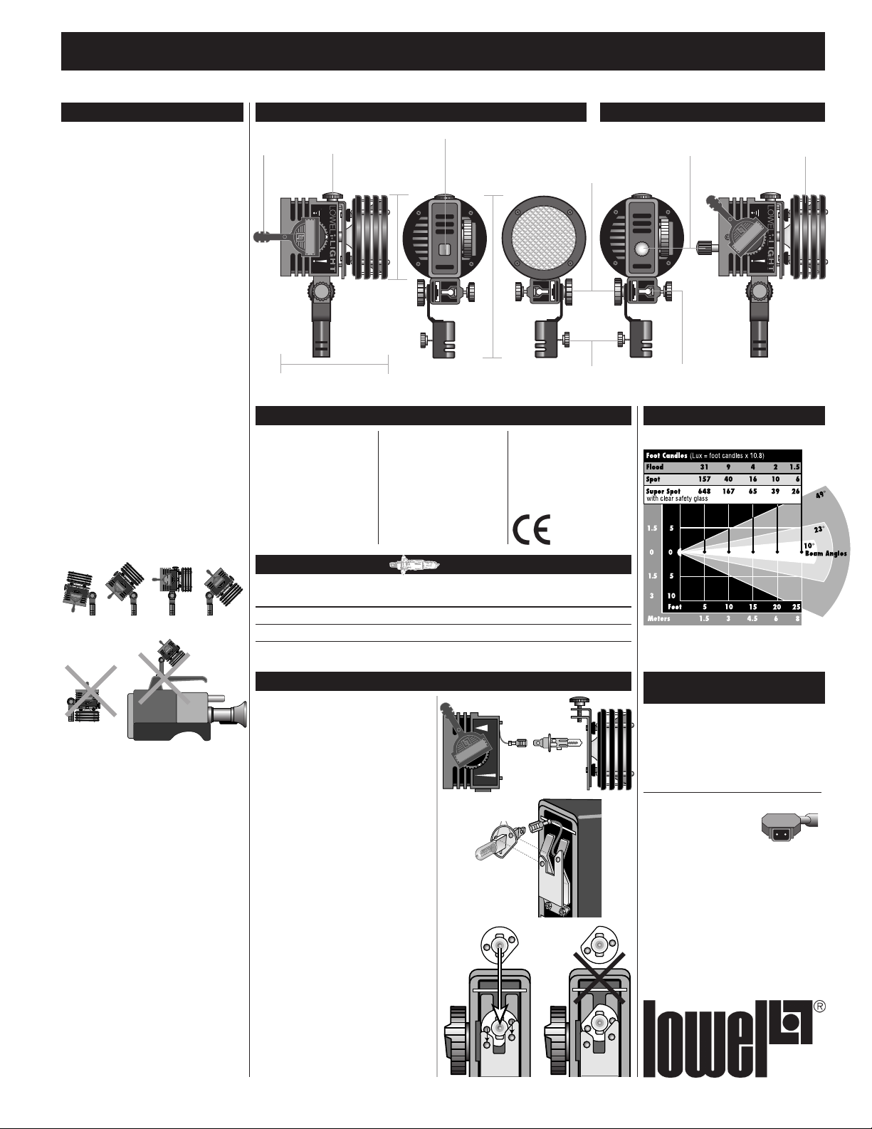
i-light id-light
Focus
knob
Screw-in lock
for front-end
4.6” (11.7 cm)
AC switch 20 KHz Rotary
3.7” (9.4 cm)
160° constant tension
no-yoke tilting from
stand-fitting. Stand fitting can
swap for accessory handle
6.7” (17 cm)
Stand fitting & locking knob
for 5/8” stand tops
i-light Technical Data
Weight:
i-light with 4' cable:
1.2 lbs (544 g)
id-light with 4' cable:
1.5 lbs (635 g)
Max wattage: 100
Max amperage: 8.3
Beam control:
continuously variable
Fits on: stands, studs,
camera tops, etc.
Materials: primarily
aluminum and Ryton
Cable: 4' (1.25 m) #16/2
with cigarette lighter
connector CE Model with
#18/2 cable
Switch: in-head
U.S. Patent: 4777566
Lamp/Beam Data
Lamp Volts Watts °K Avg F. C. (lux) at 10' (3 m)
Code Life Flood Spot Focus Range Super Spot
i-100 12/14 100 3200 500 hr* 9 (99) 40 (430) 5:1 167 (1800)
i-55 12/14 55 3200 500 hr* 4 (40) 29 (315) 8:1 120 (1300)
*At 12v.
Front-end comes
dimmer control
Slot & lock for umbrella
and gel-frame
off for easy, no-tool
lamp change
Performance
With 12v, 100w, 3200°K, i-100 lamp
Beam angles-points at which intensity drops
to 50% of maximum
n Do not tilt light down if mounted on
top of a camera, while illuminated. Camera
damage could result.
n Do not leave fixtures unattended.
n Unplug fixtures when not in use.
n Never touch hot parts only touch
handles & knobs for light adjustments.
n Do not touch i or id-light upper front
end knob while operating the light,
high temperature is present.
n Lights should be operated with lamp
filament horizontal.
n Avoid mounting lights directly over
people unless secured with a safety cord
or cable.
n Keep light power cable away
from front housing when hot, to avoid
damage.
n Never store i or id-light without first
removing the power cable from the power
source.
i & id Lamp Replacement
1 Turn focusing knob A to spot position.
2 Unscrew the small knob B located on top
of the front reflector assembly. Remove
front assembly by tilting “downward”.
3 Holding the focus knob in spot position
grasp the rear metal portion of the lamp C
and push in.
4 This will release the two “dimple” studs D
which seat the lamp in its socket.
5 While continuing to push the lamp
assembly E in, gently slide it upwards
and out of the socket. Slowly pull the
lamp forward slightly. This will expose
a single-wire connector F.
6 Separate the lamp from the single-wire
connector. Make sure single-wire
connector does not fall back into the
lamp housing.
7 Connect this wire to the replacement
lamp. Align connected lamp with the
flat side of the metal lamp base facing
down (the 4 o'clock position).
8 While pushing in, gently slide the lamp
downwards until the two “dimple” studs
are seated in the socket.
9 Replace the front reflector assembly
and tighten the top knob.
i & id Power Cable
AB
C
F
DEF
C
& Connectors
The i-light standard power cable terminates
in a standard cigarette lighter plug.
Special i-lights are avalible with 4-pin XLR,
or Anton Bauer (2 pin battery plate, camera)
cable connectors.
i & id-light Connector
i-86 Anton Bauer
The Anton Bauer connector can be supplied
by a Lowel Dealer or directly from Lowel for
installation by a qualified electrician.
NOTE: If you connect a battery with
reversed polarity (plus is minus /
minus is plus) to the id-light, the fixture will not light, and a red warning
LED will illuminate on the side of the
fixture.
Battery Tap
Page 2
Lowel i & id-light Instructions
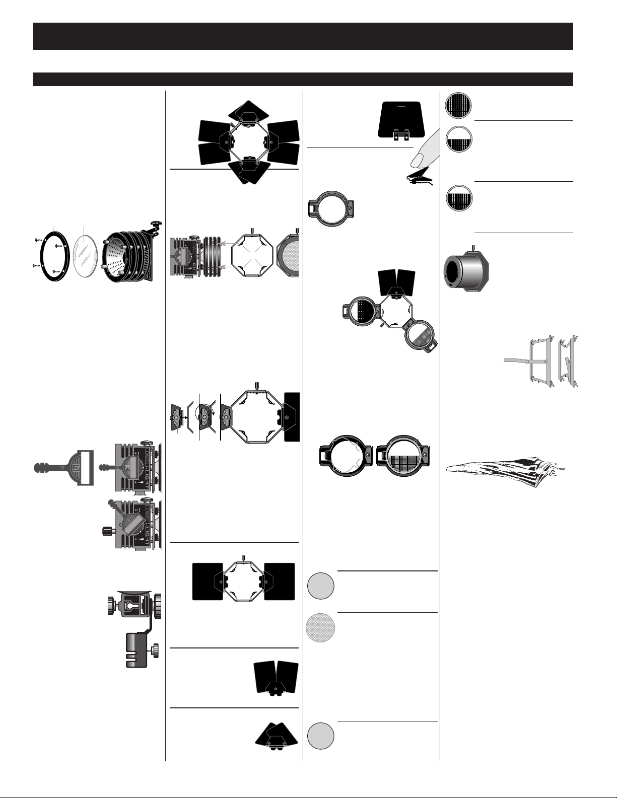
Light Control s
i & id- lights are supplied with the
iP #2 Reflector
This computer designed, faceted high intensity reflector gives improved light output. It can
be used with either the supplied Prismatic
Glass (focusing) or Clear Safety Glass (high
intensity non-focusing super-spot only).
Never operate Pro or i / id-lights without prismatic or safety glass installed.
Changing Pro & i / id
Front Housing Glass
(Prismatic or Clear Safety)
A
B C
1 Remove the four screws A located on the
front of the light and lift off the cover plate
B, and the Prismatic Glass C
2 Replace the Prismatic glass with Clear
Safety Glass. Reassemble in reverse.
Another option is to purchase the
#2 Reflector with Front
Housing & Safety Glass
Code: iP2-19
Pro & i / id Focusing and
Focus Knob Extension
Code: iP-35
Turning focusing knob, located on the side
of the housing, alters
the beam of light
from flood to spot. A
focus knob extension
accessory snaps into
focus knob for left-hand
or on-camera focusing.
Compact filament lamps may fail if subjected
to shock or vibration while on. Operating the
focus smoothly will help prevent lamp failure.
Attaching
gel frames
A
& umbrellas
i & id-lights have
a Universal Mounting Bracket
(UMB) A located below the
fixtures adjacent to the stand
fitting B. It facilitates the
mounting of i / id & other ViP Lights
to stands and accepts several light control
accessories.
B
Pro-light & i-light
arndoors
B
Barndoor Frame
Code: iP-21
Accepts swing-in accessories, and/or leaves.
Rotates 360°.
Attaching the Barndoor Frame
to the front of the light with and without
barndoors.
1 Loosen the knob A on the Barndoor
Frame.
2 Set the frame clamp retaining feet B into
the first ventilation groove C of the light.
3 Tighten knob. Proper installation allows
full 360-degree rotation of the complete
barndoor assembly.
Attaching the leaves to
the Barndoor
A
Expandable Leaves and Nonexpandable
barndoors are attached to the frame by constant-tension lock fasteners A located on the
rear of the doors. The lock fasteners require
a 1/2 (180-degree) turn to remove or install
the barndoors. Lock fasteners should be on
the “inside” of the barndoor flap, It is possible
to install a barndoor leaf backwards so that
it will not close over the light. It is important
to align the barndoor leaf to the frame.
2-way Barndoor
Barndoor Frame with two removable nonexpandable leaves. Frame accepts
swing-in accessories and additional leaves.
Rotates 360°.
Expandable Rectangular Leaf
Code: iP-22
Changes from small to
large rectangle.
Expandable Triangular Leaf
Code: iP-23
Changes from triangular
to square shape.
AC
B
Code: iP-25
Non-expandable Clip-on leaf
Code: iP-24
Rectangular leaf. Can be
attached to, or removed
from, Barndoor Frame.
Gel-Jawz
Attach to barndoor leaves to hold
gels. Use two per light.
Code: CL-15
Swing-in
Accessory
Holder
Holds Light Control
Accessories, attaches to the Barndoor Frame in
a similar manner as the barndoor leaf. Align
Accessory Holder on Barndoor Frame. The
lock fastener requires a 1/2 (180-degree) turn
to remove or install the
Accessory Holder. When
in use, Accessory
Holder
swings over
the light and
locks onto the other
side of the frame. Three holders
can be attached to the Barndoor
Frame simultaneously, but only one can be
used at a time. A full barndoor set and a single
holder can be used at once. Quickly swinging
one holder out of position and swinging in
another is a valuable user convenience.
Code: iP-30
Changing Light Control
Accessories
Simply release the captive retaining spring clip
located inside the Holder and remove accessory. Insert new accessory and secure retaining
spring clip. A scrim and glass accessory may
be mounted together in a single Accessory
Holder. Separate holders for each accessory
are recommended for fast in-use changes.
Swing-in Accessories
Diffused Glass
softens highlights and shadows.
Absorbs U.V. Iight rays Light loss
approximately 40%.
iP Prismatic Glass
Code: iP-52
Supplied with all Pro & i-lights.
Gives an evenly dispersed flood,
produces a more uniform spot and
a fresnel-like barndoor cut. When
used in holder with Clear Safety
Glass (iP-49) installed in front
housing, allows focusing use when
swung in & super spot use when
swung out.
Dichroic Filter
converts 3200 K lamps to average
daylight; absorbs U.V. Iight rays
Light loss approximately 65%.
Code: iP-50
Code: iP-51
2
Full Scrim
reduces light by approximately
one stop.
Half Scrim
covers half of reflector and rotates
360° darkens washed out
foregrounds, compensates for
actors “burning up” as they
approach a light.
Graduated Scrim
Code: iP-56
same principle as half scrim
but effect is more gradual
and more extreme.
Snoot
as does a Barndoor Frame. iP
Snoots can be “piggy-backed.”
Code: iP-54
Code: iP-55
Code: iP-53
Produces a reduced circle of
light; Barndoors and barndoor accessories may also be
added to the end of the
Snoot. A Snoot attaches to
the light in the same manner
Pro & i Gel Frame
Code: iP-40
Holds 5 x 6" gels.
Unfold frame,
extending frame bar and
insert through front slot of
UMB Lock with knob. Pans and tilts with the
light, collapses for storage.
Pro & i Gels
Size: 5 x 6" (12.52 x 15.25 cm) sheets
Tota-brella
Photographic umbrellas
convert relatively hard light sources,
such as spotlights, into relatively soft sources
that provide soft shadows and highlights.
Although not appropriate for every subject
or mood, the quality of light can be very
beautiful. There are two umbrellas suitable
for use with the i & id lights:
Silver (Code: T1-25), reflective umbrella.
White (Code: T1-26), a white nylon
umbrella that produces a softer light and also
may be used as a large diffuser. To mount
umbrella insert umbrella shaft through round
hole in UMB and lock with knob. Tota-brella
and Tota-frame cannot be used simultaneously.
Warning - When lights with umbrellas are
extended very high, or used on undersized
stands or in areas of heavy “traffic”, it is
advisable to add weight (such as the Lowel
weight) to the base of the stand to reduce the
chance of lights falling over which could
damage the umbrella, the lamp and possibly
cause personal injury.
Warning - To prevent possible umbrella
damage, avoid full or near-full spot reflector
settings on the i or id-light and do not use
with a Clear Glass as Super-spot.
Page 3

Stands
The i & id-lights will lock onto stands with
top studs up to 5/8” (16mm). We recommend
the Uni-stand or Uni TO Stand, for most
applications. Where elevation greater than 7’
9” is required, we recommend Lowel KS
stands with Half or Full Poles. i or id-lights
can be positioned low on any stand with a
Tota-clamp. Lowel-weights add to stand stability and should be used when appropriate.
Uni-stand
Code: UN-33
Size: 21.5"
(54.6 cm) folded.
Extends to 7'11"
All aluminum stand,
wide base, legs can lie
flat to floor,
large locking
knobs. Folds compactly
to fit in smaller kits.
Uni TO Stand
Code: UN-55
Size: 21.5" (54.6 cm)
folded.
Maximum height:
7'11" (2.4 m)
Base diameter: 43"
New stand,
based on
design
combination of Uni-stand
& Omni-stand. More stable than
Uni-stand, more compact than
Omni Stand.
Vipod & Stud-link
Code: ViP-35S
Supports i / id or other ViP Lights
on flat surfaces. Vipod can be
screwed, Gaffer-taped or
clamped to vertical surfaces. Stud-link is removable. The Low Link can
also be mounted on the
Vipod by attaching the Low link to the Vipod
using the knob provided with the Lowel link.
Tota-mount
Code: T1-32
Tota-mount supports
any of the ViP fixtures
atop doors and partitions. Doors can be
open or closed.The
light can be inside or
outside room, since swinging arm extends
past most door jambs. Tota-mount can be
flipped over and nailed to studio set walls or
Gaffer-taped to windows or tile, wood, metal
and other wall surfaces.
Mounting Tota-mount &
Vipod with Gaffer Tape
Use 12”of
Gaffer-tape
on each bar
on Tota
Mount or
side of Vipod
and burnish
down with a
coin. Avoid
wallpaper,
Lowel i & id-light Instructions
soft composition board or flaking paint. Never
attach to the ceiling with tape. Use original
Lowel Gaffer-tape. Many substitutes leave
adhesive residue or lack sufficient strength.
When properly attached, Tota-mount or Vipod
will support the Iight for days. However, on
dirty or poorly bonded surfaces, or with
improper or poorly applied tape, there is the
danger of the mount falling down and causing
serious damage. Check adhesion periodically.
Prevent direct light from overheating tape.
Remove tape when cool, by peeling back
diagonally. Tota-mount should not be used
with lights heavier than 3 lbs. (1.33 kg)
Tota-clamp
Code: T1-30
Tota-clamp supports most lights
that fit standard 5/8” studs.
Tota-clamp can be attached to
pipes, stands, or flat surfaces.
When clamping on furniture, use
thin wood or cardboard to avoid
marring. To rotate stud, turn wing
nut counterclockwise several
turns. The stud can be locked in any of four
positions; two for the 5/8” stud and two for
the end with the 1/4-20 tapped hole. A 1/4-20
screw can be used to lock on some microphone yokes and various accessories.
Tota-clamp has two snap-in fittings
for Flexi-shafts.
i & id-light Mounts
Scissor Mount
Code: CM-20
Attaches i or id-lights, and Vlights to dropped ceiling: Clamp X
bars of grid lock to T-Bar of ceiling.
Attach fixture to mount stud and
tighten. Pro lights should use the
Grid Lock for dropped ceiling
mounting. Avoid mounting fixtures
directly over people unless secured
with a safety cord or cable.
Caution: Camera damage may result if light
is pointed down while lamp is on.
L-link
Code: ViP-36
Can be used to extend i or id-lights from
Cam-links and Vipods. To use, mount
short leg of L-link on to Cam-link or
Vipod using the knob provided. Remove
Stand-link from fixture by loosing the large knob, attach light to
upper part of slot with the large
knob.
Low-link
Code: ViP-37
Enables i & id-lights to be
mounted on Cam-links and
Vipods.
Stud-link
Code: ViP-38
5/8 “ (16mm) stud with 1/4-20 male
screw, used to mount fixtures with
Stand-link to cameras with proper
female socket.
Professional Camera & Handheld Mount Options
Cam-link
Code: ViP-41
Male “shoe” fitting locks into
cameras with proper female
shoe mount. Accepts Stud-link
Low-link or L-link.
Cam & Stud-link
Code: ViP-41 S
For mounting fixtures with Stand-link on cameras with proper female shoe mount. Slide
Cam-link onto camera shoe, screw Stud-link
into top of Cam-link to tighten. Do not over
tighten! Mount light on stud and secure by
tightening Stand-link lock knob.
Cam & Low-link
Code: ViP-41 L
For mounting fixtures directly on cameras
with proper female shoe mount. Remove
Stand-link from fixture by undoing the large
attaching knob located on the side of the
fixture. Attach low link using the upper hole
and with the “leg” facing “under” with the
large knob. Mount the Fixture/ Low-link
assembly to the Cam-link, using the knob
provided. Slide the Cam-link/light assembly
onto camera shoe, secure by tightening knob
on Cam-link. Do not over tighten!
For additional information
on the following products, consult product
instruction sheets, relevant sections in
the Lowel Catalog or visit the Stands &
Mounts section of www.lowel.com:
Space-clamp, Lobo, Lobo Arm, Grip,
Inter-link, Screw-in Stud.
Handle & Stud
Code: ViP-431
Weight: 3 oz (85 g)
For hand-holding i / id &
To use, attach stud to
handle, mount fixture on stud
securing with Stand-link knob.
3
Page 4

Lowel i & id-light Instructions
& id-light for the New Professional
i
Use the i & id-light as a convienent, lightweight, DC powered source
for a flexible key, fill or back-light that goes places that the AC cable can’t.
Adding accessories will extend your creative possibilities.
id-light notes:
When using the id-light, keep in mind that its lamp will shift
its color temperature warmer as the light is dimmed.
If you find a particular dimmer setting that you use most often,
store a white balance in your camera with the light at that
dimmer setting. Then use a grease pencil to place a mark
on the body of the light that lines up with the white line on
the dimming control. In the future, you can return to that
dimmer setting quickly and have a prestored white balance
for it in the camera.
Use the focusing knob
to move from Spot (narrow beam) to
Flood (wide beam). Its 5:1 focus
ratio (when used with a i-100 lamp)
means that the spot setting will be
approximately 5 times as bright as
the flood setting (at full brightness
for id).
The i & id have a high intensity reflector & prismatic
glass installed. This combination gives an even output with
a fresnel like quality in the shadows, an evenly dispersed flood,
and a uniform spot with significant barndoor cut. It is capable of
throwing sharper shadows when used on its own. Add a diffusion glass swing-in accessory, diffusion gel with a gel-frame, or
attach an umbrella to create a softer source.
Because the i & id-lights are tungsten-halogen
sources, their color temperature will be aprox 3200°K (at full
brightness for id), To use the light in locations where its output
will mix with daylight (5600–6500°K ), its color temperature
can be converted by attaching a Dichroic Filter swing-in accessory, or adding day blue gels to the Pro & i gel-frame. Both
will give more realistic daylight white-balancing in video or
film. Using gels will give more versatility since they are available in 1/2 & 1/4 strengths of full blue. Note: adding day blue
gels or dichroic filters will reduce output.
Swap the Prismatic Glass to Clear Safety Glass for
non-focusing higher output Super-Spot. This can be useful
when lighting a small area from a greater distance, where higher
output is needed. For faster switching on location, try using
Clear Safety Glass in the front housing & placing the Prismatic
Glass in a swing in accessory holder. Use the light for normal
focusing with the accessory swung in, and then swing it out of
the way for quick switch to super spot.
For more reduced spill, consider adding a Snoot.
Other front accessories can help vary the quality of
the light output. For example, the rotating half-scrim can
allow you to reduce light output on a close subject while still
illuminating subjects further away with full output. The full
scrim reduces output without the use of a dimmer which can
shift the color temperature warmer as the lamp is dimmed.
The oversimplified diagram below shows some of the
ramifications of positioning lights for different subject types
& lighting effects. This diagram is only useful as a starting point for new pros. All subjects & scenes are different and make different demands upon lighting. The
height of the lights & camera, and the subjects angles & reflectivity must be considered.
Note: in stationary use
with battery belt, placing belt around stand
bottom adds ballast to
help prevent accidental
tip-over.
Use the rotating barndoors to trim unwanted output spill,
(for example: to reduce risk of shadow in your shot caused by
use of overhead boom microphones). Flexi-shafts & Tota-flags
can also be attached for increased light control options.
Dealers, Repairs, etc.
Lowel equipment and kits are sold through authorized Lowel
Dealers and, in some countries, Authorized Lowel Distributors.
Repairs, problems, suggestions, and requests for brochures,
instructions, parts lists may be handled by your authorized
Lowel Dealer (Distributor) or directly with Lowel.
Electrical repairs should be made only by Lowel or a qualified
electrician. Lowel ViP System, Lowel V-light, and Lowel
Pro-light are trademarks of Lowel-Light Manufacturing, Inc.
Patent Nos. 4777566, 4322779, 0011772 (Europe), 1292007
(Japan).
Ver. 2.2 © 2010 Lowel-Light Mfg, Inc. 910
Lowel-Light Manufacturing, Inc.
90 Oser Avenue, Hauppauge, NY 11788
Call: 800 645-2522 or 631 273-2500
e-mail: info@lowel.com
www.lowel.com
4
 Loading...