

Page 1
Studio Fluorescent Instructions
Warnings
The Lowel Fluo-Tec fluorescent studio
line is a professional lighting system.
Read these instructions and lamp
manufacturers warnings before
operating. See Back Cover for
important fuse information.
n Do not leave fixture unattended.
For stationary (studio) use.
n Not for household use.
Use only for photographic lighting
(video & film imaging).
n Do not exceed maximum rated
wattage for unit.
n Use maximum 55 Watt lamps.
n Always unplug unit before
relamping.
n Always unplug unit before
changing fuse.
n Be sure lamp is securely seated
in lamp socket.
n Do not use near standing water.
n Internal ballasts produce high
start-up voltage.
n Never bypass plug’s ground pin.
n Do not interfere with unit’s
ventilation.
n Do not operate unit with
Barndoors closed.
n Make sure clamp is tightened
at yoke.
n Always use Safety Cables,
when attaching to overhead pipes or grids.
n Do not attempt to open unit,
no user serviceable parts inside.
n Always use with supplied Lowel
AC Cable.
Fluorescent Warnings
n Avoid looking directly at the tubes
for extended periods of time.
n Fluorescent tubes contain highly
poisonous mercury.
n In the event of lamp breakage,
avoid contact with broken pieces,
and dispose of properly.
n Read lamp manufacturers
information fully.
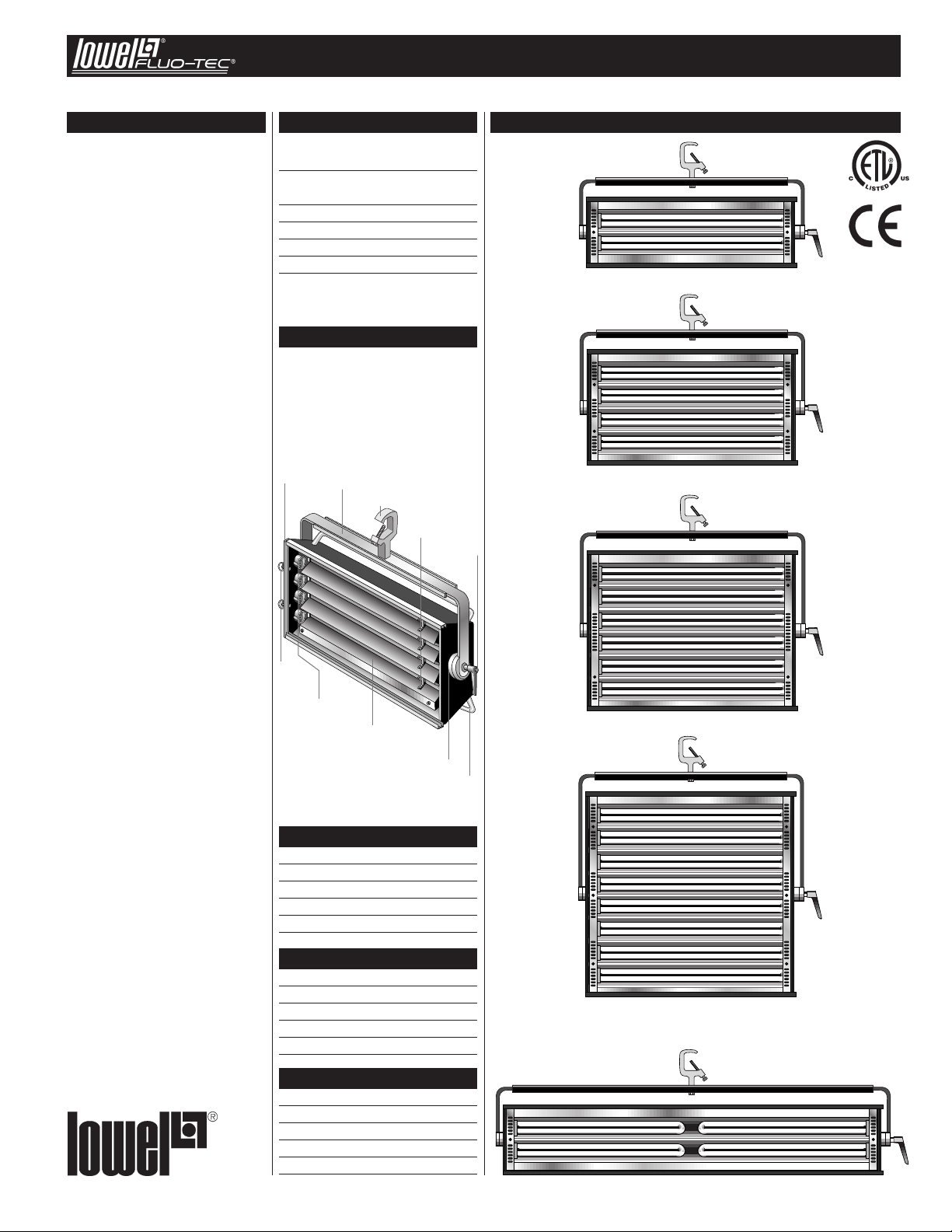
Contents
Using Lowel Fluo-Tec
Front Accessories 2
Lowel Fluo-Tec Models
& Control Panel 3
Lamps & Fuse Change 4
Fuses & Power Consumption 4
Mounting the Fixture 4
Problems, repairs & info 4
Each fixture comes with:
n Gel frame
n 3 safety cables
n Standard C Clamp yoke
mounting device
n Standard AC power cable
with male Edison connector
Accessories
Door
Doorflap
Locks
Yoke
Lamp
Sockets
Clamp
Lamp
Holders
Chassis
Reflecting
Mirrors
Brake Disk
Control
Handles
Studio 250DM
tudio 250PHD
S
tudio 250ND
S
Studio 450DM
tudio 450PHD
S
Studio 450ND
Studio 650DM
Studio 650PHD
Studio 650ND
Studio 850DM
Studio 850PHD
Studio 850ND
Lowel Fluo-Tec Models
Dimmable Models
• Studio 250DM
• Studio 250cyDM
• Studio 450DM
• Studio 650DM
• Studio 850DM
Phase Dimmable Models
• Studio 250PHD
• Studio 250cyPHD
• Studio 450PHD
• Studio 650PHD
• Studio 850PHD
Non-dimmable Models
• Studio 250ND
• Studio 250cyND
• Studio 450ND
• Studio 650ND
• Studio 850ND
Studio 250cyDM
Studio 250cyPHD
Studio 250cyND
Page 2
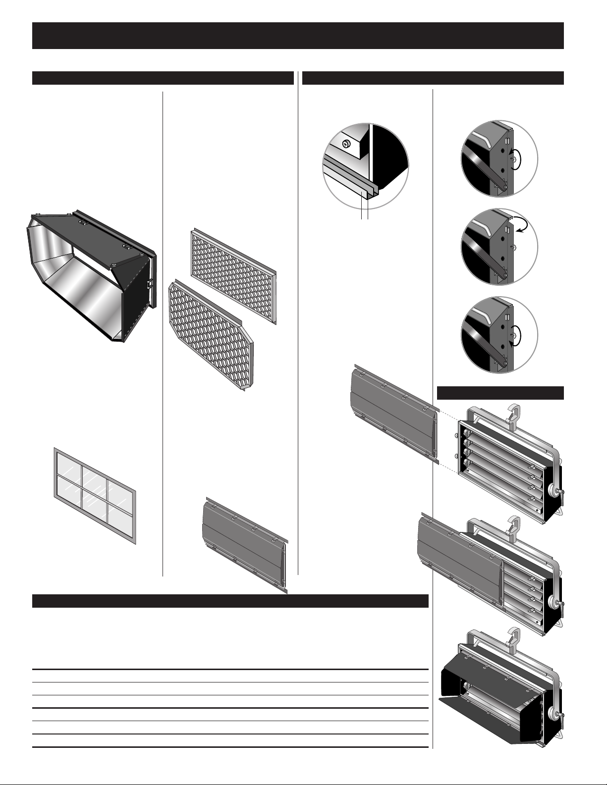
Using Lowel Fluo-Tec Front Accessories
Front Accessories
Intensifier:
The mirrored Intensifier, when attached,
can almost double the light output of the
fixture. Assemble before attaching to light.
Intensifier is a one piece unit that unfolds
and locks together at its corners. Take care
to make sure that all quarter-turn locks are
securely fastened. Slide assembled intensifier
into front slot of fixture, close doorflap
and secure twist-locks Note - Intensifier has
grooved slot on front for attachment
of Honeycomb Grid to trim light.
Choose correct size of Honeycomb Grid.
Gel Frame:
For using colored or diffusion gels in front
of the fixture to change the color of the light
or to diffuse it further. Slide the pre-cut gel
material into the hinged frame, taking care
to trim any excess that falls outside the frame.
Slide the frame into the slot closest to the
lamps on the front of the fixture. Close &
tighten locking door-flap.of the fixture.
Honeycomb Grid:
Each fixture has 2 options for using honeycomb grids to control the spill of the light,
either placing a grid on the front of the fixture,
or attaching one to the front of the Intensifier.
Because the front of the intensifier is a different size & shape than the front of the fixture,
there are specific models for each use. It is
not possible to use the “front of fixture” grid
with the Intensifier installed. The grids are
available in black with 20, 30, or 40 degree
dispersions. If you are at all unsure of
which honeycomb to use, contact us.
Honeycomb Grids cause some loss of light
output (see chart).
Egg Crates:
for controlling spill. Slide the Egg Crate into
the front accessory slot. Less control than
Honeycomb Grid, with less output loss.
Barndoors:
For trimming spill of the light, slide Barndoor
assembly into front slot on fixture, close doorflap and secure twist-locks. Open doors and
adjust for proper trimming of spill. Do not
operate unit with Barndoors closed.
Slide-in Slots
There are 2 slots in front of the fixture
for slide-in attachment of Front
Accessories.
Slot ASlot B
Slot A
closest to the lamps is for slide-in attachment
of the Gel Frame accessory
Slot B
furthest from the lamp is for attachment
of all other accessories.
Slots are accessible by releasing
the twist locks and opening the door-flap
on the front left side
The following available Front
Accessories can be attached to the
front of the fixture:
n Gel Frame (supplied),
n Egg Crate Grid,
n Honeycomb Grid (front of fixture model),
n Intensifier (except Model 250cy),
n Barndoors
Slots are accessible by releasing
the twist locks and opening the
door-flap on the front left side
Step 1
Step 2
Step 3
Sliding in Accessories
Step 1
Honeycomb Grids Comparison
The grids are black and available in 20, 30, or 40 degree dispersion for the front of the fixture or the front of the Intensifier. Honeycomb Grids
cause some loss of light output. Consult the below chart to determine the proper code for the chosen grid.
sion°
Disper
Black 40° Front of Fixture 25% FLS-834 FLS-634 FLS-434 FLS-234 FLS-2534
Black 30° Front of Fixture 35% FLS-833 FLS-633 FLS-433 FLS-233 FLS-2533
Black 20° Front of Fixture 54% FLS-832 FLS-632 FLS-432 FLS-232 FLS-2532
Black 40° Front of Intensifier 30% FLS-844 FLS-644 FLS-444 FLS-244 N/A
Black 30° Front of Intensifier 22% FLS-843 FLS-643 FLS-443 FLS-243 N/A
Black 20° Front of Intensifier 46% FLS-842 FLS-642 FLS-442 FLS-242 N/A
Grid
Placemen
t
Output Loss
Studio 850
tudio 6
S
tudio 45
S
0
50
tudio 25
S
0
S
tudio
5
2
2
Step 2
cy
0
Step 3
Page 3

Dimmable Models
1 2
3 4
The fixtures of the Lowel Fluo-Tec studio
line are all available in dimmable models,
which can be controlled either manually on the
fixture or remotely via DMX-512 protocol
(console of IR DMX Controller). To operate
the Control Panel, first familiarize yourself
with the placement and functions of the
controls. Note: Fluorescent systems typically
require a minute or 2 to reach full brightness
on cold startup, depending on ambient
room temperature.
Control Panel Functions
AC Power Switch
Turning on the AC Power switch, starts the
fixture’s dimmer at whatever level it was at
when last powered down (factory shipped
at 100%). The unit will retain its previous
dimming level even if unplugged.
MODE Key/LED Display
Repeated pressing of the MODE Key scrolls
the unit thru its various control functions,
as displayed in the LED Display window.
MODE displays, in order of appearance:
1) Hours of lamp operation,
2) Unit dimming level (preceded by L),
3) Dimming to 0% or 1% (LP on oF)
4) DMX address (preceded by A).
If a valid DMX signal is detected, fixture will
automatically display its DMX address (ex. A1). However if another display MODE is chosen, it will display that mode until the fixture is
powered down or DMX signal is lost.
Model & Software Version Display:
When the unit is first powered up, the LED
display will scroll the model name of the
fixture (ie.–Studio 250cy), followed by the
version number of the installed software
(ie. r2-3, for version 2.3). Make note of the
software version number in case the fixture
needs service.
1) Hours:
The manufacturers expected lamp life is
approximately 8 - 10,000 hours. The display
counts the hours of lamp operation between
0 to 9,999 hours. If the hours pass the 9,999
point, the display will flash 9999 indicating
that it is time to change the lamps.
To reset the counter after relamping, while
in the Hours mode, hold down the MODE key
for over 4 seconds. This resets the counter
to 0. To avoid confusion, it is recommended
that you replace all lamps in the fixture at the
same time if you plan to monitor lamp life
with this function.
2) Unit Dimming Level:
This value (preceded by L) shows either the
level set using the Up/Down Arrows (Manual
Mode), the level stored in a selected Memory
(1-4), or the level as controlled by the DMX
lighting console (DMX Mode). All models
have a dimming range from 100% to 0%
or 1%, depending on how the fixture is set.
3) Dimming to 0% or 1%
The dimmable models with software revision
2.3 or later can be set to dim fully from
100 to 0%, or from 100 to 1% depending
upon user preference.
Fixtures dimmed to a minimum of 1% can be
quickly dimmed up full, whereas fixtures
dimmed to 0% will experience a brief delay
in graceful dimming as the lamps start up.
To set the fixtures, first make sure they are
not connected to a DMX chain. Scroll thru the
MODE menu on the back of each until you
reach "LP on oF" on the LED display. Holding
the MODE button for 3 seconds will toggle the
function between “LP on” & “LP oF” (Off).
“LP on” means the lamp powering will dim
down to 0% when control is faded all the way
down, and “LP oF” means the lamp powering
function is kept at 1% when control is faded
all the way down. This setting gets saved
inside the fixtures memory, even when
powered down, and is in effect regardless
of manual or DMX dimming.
4) DMX Address:
DMX-512 protocol allows you to assign
one of 512 possible control addresses to the
fixture. The letter A precedes the DMX
Address of the unit.
Up/Down Arrows
Used for moving up or down in numerical
value for functions chosen by the MODE key.
ex. – manual dimming, DMX Address selection, etc.
MEMORY
The 4 Memory buttons are used to select &
recall stored dimmer levels.
Manual Dimming
The dimming level of the fixture is shown with
a value that begins with L. Manual dimming
can be controlled with the Up/Down arrows
on the control panel of the fixture, or by the
4 stored Memory settings. The unit will
restore its last dimming level, when powered
AC
Input/Fuse
MODE
Key
AC Power
Switch
MEMORY
buttons
arrow
Lowel Fluo-Tec Models & Control Panel
Control Panel & Using Dimmable Models
up even if it has been unplugged. Manual
dimming can only happen if the unit is not
receiving a valid DMX signal from the
console. All models have a dimming range
from 100% to 0% or 1%, depending on how
the fixture is set.
Using Memories
When using the unit manually (non-DMX
operation) there are 4 user-storable dimming
memories, which will be saved, even when the
unit is turned off and unplugged.
To store a memory setting,
1 Bring the fixture to the desired level (for
example 72%) using the Up/Down Arrows.
2 Hold down the chosen memory key for 4
seconds. The display will flash, and the level
will be saved. When you press a memory button, it will recall the setting saved on that
memory.
The unit is shipped with 4
factory preset memory settings
1 – 25%
2 – 50%
3 – 75%
4 – 100%
To recall a memory setting,
Press a Memory button (1-4) to bring the fixture to its previously stored level.
Dimming (via DMX)
To set or change
the DMX address:
1) Make sure the unit is not receiving a DMX
signal by either turning off console, or disconnecting DMX cable.
2) Press the MODE Key repeatedly to scroll
the LED to DMX Address.
3) Hold down the MODE key for 4 seconds.
The DMX address will flash, and you can then
set or change that address by using the
Up/Down arrows from 1 to 512.
4) After selecting the desired DMX address,
hold down the MODE key for 4 seconds, and
the address will be saved, even when the unit
is turned off and unplugged, until it is reset
again as described above.
Up
LED Display
arrow
Remote
Port
DMX In
DMX OutDown
Connecting for DMX Use
To control a single unit using DMX-512,
connect a DMX cable between the output of
the console and the DMX In connector
on the back of the unit.
DMX connections to multiple units must be
daisy chained from the consoles DMX Out
to the 1st unit’s DMX In connector, and then
from that unit’s DMX Out connector to the next
unit’s DMX In connector, etc. For proper
DMX operation, the final unit should have
a DMX terminator plugged into its
DMX Out connector.
Note: When the unit is receiving a valid DMX
signal, the only active function that you can
use manually on the rear control panel is the
MODE button. You cannot set or recall memories, set the DMX address, change dimming
status between 0 & 1%, or reset the lamp
hour counter.
DMX Dimming
While you are in DMX mode (as soon as
you plug in the console and there is a valid
DMX signal), the LED Display will show the
DMX Address of the unit. Its level will reflect
the intensity sent by the console for that
channel. All models have a dimming range
from 100% to 0% or 1%, depending on how
the fixture is set.
Remote Port
The unit can also be controlled by the optional IR DMX Controller, a handheld wireless IR
remote control for use in controlling single or
multiple units without the need for a DMX
console. See “IR DMX Controller for use with
Lowel Fluo-Tec Studio Fluorescent System”
instructions, for more information.
Phase Dimmable Models
Phase Dimmable models do not have
dimmmers installed inside. Instead they have
the ability to be dimmed via an AC powered
phase dimming system.
Plug the AC cable of fixture into dimmer and
power the fixture up, to control via the dimmer.
Non-dimmable Models DMX Dimmable Control Panel
All non-dimming models have multiple lamp
switches, each controlling 1 pair of lamps
(except Studio250). Output can be varied
by use of the switches.
Model Switches x Lamp-pairs
Studio 250 1 x 1
Studio 250cy 2 x 2
Studio 450 2 x 2
Studio 650 3 x 2
Studio 850 2 x 4
Note: Fluorescent systems typically require
a minute or 2 to reach full brightness on cold
startup, depending on ambient room
temperature.
3
Page 4

Studio Fluorescent Instructions
Lamps & Fuse Change
Lowel Fluo-Tec fluorescent studio fixtures
use compact (55 watt) fluorescent lamps.
See lamp manufacturers specifications for
additional information.
Osram Studioline®Lamps (Video/Digital)
Designed for use in video & digital imaging for more
accurate color rendering and higher output. Mixes with
tungsten/ halogen sources. Mfrs rated life - 8,000 hrs.
Tungsten CRI Color Temp.
FL-55OTU Studioline 55w/3200 85 3000° K
Daylight CRI Color Temp.
FL-55ODA Studioline 55w/5600 85 5600° K
GE Cinema-Plus Lamps (Film)
Better lighting for film (still or motion picture) due to better color rendering with film emulsions. May require 1/8
“minus green” filtration gel. Mfr. rated life - 8,000 hrs
Tungsten CRI Color Temp.
FLC-55TU* GE F55BX/CINPLUS32 90+ 3200° K
Daylight CRI Color Temp.
FLC-55DA* GE F55BX/CINPLUS55 90+ 5500° K
Lamp Installation &
Change
Facing the fixture, the base of the
lamps are on the left side (except
for model 250cy which has lamp
bases on both sides). To remove
a tube, gently grasp it by the
glass end (furthest from socket)
and swing it slightly out from
the spring clamp that holds the
center of the lamp tube, away
from the fixture while pulling it
carefully straight out from the
socket. Replace lamp in same
way, opposite order. (Be very
careful as lamp-tubes are fragile
and can easily shatter,
read Warnings).
Fuse Change
All fixtures come with a
user-replaceable mini-fuse which
is installed in a small holder on
the exterior AC power socket.
Access the fuse by removing the
cap with a small flathead screwdriver. Swap fuse if necessary
and replace holder. Consult the
chart on page 2 or the back label
the fixture to confirm proper
replacement fuse.
Fuses & Power Consumption
Note - Most electrical equipment briefly consumes a higher amount of electrical current during
startup (ignition). Consult the below chart to confirm that your electrical wiring is sufficient for
the fixtures used. All fuses must be rated at 250VAC.
120 Volt Model 50/60Hz
DMX Dimmable Models
Integral ballast operating frequency:
40-60 Khz
Power factor: >97
Model Fuse Nominal Peak
Current Ignition
Current
850DM 6.30 A 4.02 A 6.00 A
650DM 5.00 A 2.96 A 4.00 A
450DM 3.15 A 2.00 A 3.00 A
250DM 1.60 A 1.05 A 1.50 A
250cyDM 3.15 A 2.00 A 3.00 A
Non-dimmable Models
Integral ballast operating frequency:
26 Khz
Power factor: >70
Phase Dimmable Models
Integral ballast operating frequency:
40-60 Khz
Power factor: >97
Model Fuse Nominal Peak
Current Ignition
Current
850PHD 8 A 5.42 A 12.30 A
650PHD 6.3 A 3.80 A 8.36A
450PHD 5 A 2.70 A 6.80 A
250PHD 5 A 1.48 A 4.10 A
250cyPHD 5 A 2.70 A 6.80 A
Model Fuse Nominal Peak
Current Ignition
Current
850ND 10.00 A 4.52 A 9.90 A
650ND 8.00 A 3.41 A 7.80 A
450ND 5.00 A 2.26 A 5.00 A
250ND 3.15 A 1.15 A 3.00 A
250cyND 5.00 A 2.26 A 5.00 A
Mounting the Fixture
On Lighting Rail: Attach clamp tightly
to yoke of fixture, according to clamp mfrs.
instructions. Hang clamp on pipe or grid and
tighten the large screw so that the clamp and
fixture are securely mounted. Do not loosen
bolt attaching clamp to fixture, to position
light. Attach 1 or more safety cables between
the fixture and the rail for necessary security.
On Stand: There are 2 options for stand
mounting of the fixture, using the 5/8" female
stand fitting or using the optional Male Stud.
Choose proper size stand for fixture. For all
models, the Lowel Grand Stand or larger is
preferred, however the following stands may
also be used. Always use sufficient stabilizing
weight on stand base.
Model Lowel Stand
250cy Do not use on stand
250 KS or KSA
450 KSA
650 Grand Stand*
850 N/A**
*Do not use with top stage extended
**Use appropriate full sized studio stand.
Female 5/8" Stand-fitting: For use on
stand only. Allows mounting the fixture on
5/8" male stand stud. Make sure the stand
is large enough to support the weight of the
fixture while maintaining good balance at the
desired height. Attach the female stand-fitting
tightly to the yoke and rotate yoke so it is on
the underside of the fixture. Tighten yoke,
clamp and place female stand-fitting over
stand, making sure that its locking screw
is loosened enough to allow the fitting
to completely fit over the 5/8" stand stud.
Tighten screw, making sure it is under
the safety cut of the stand fitting stud.
Add additional weight to base of stand
for increased stability.
Male Stud: For use of fixture with Matthews
style stands that have a female cup instead
of a male stud. Attach the optional Male Stud
in the same manner as described above
for Female 5/8" Stand Fitting, again rotating
the yoke to the underside of the fixture
and tightening yoke clamp. Carefully place
Male Stud into female cup on stand top
and tighten. Add additional weight to stand
base for increased stability.
230 Volt Model 50/60Hz
Dimmable Models
Integral ballast operating frequency:
40-60 Khz
Power factor: >98
Model Fuse Nominal Peak
Current Ignition
Current
850DM230 3.15 A 2.10 A 3.00 A
650DM230 2.50 A 1.60 A 2.30 A
450DM230 1.60 A 1.10 A 1.60 A
250DM230 1.00 A 0.60 A 0.80 A
250cyDM230 1.60 A 1.10 A 1.60 A
Problems, repairs & info
Repairs, problems, suggestions
and requests for brochures/catalogs,
instructions and parts lists can be handled through your Authorized Lowel
Dealer/Distributor or directly through
Lowel. Electrical repairs should
be made only by Lowel or by
a qualified electrician.
ver. 4.0 © Lowel-Light Mfg., Inc 2010 355
Non-dimmable Models
Integral ballast operating frequency:
40-60 Khz
Power factor: >98
Model Fuse Nominal Peak
Current Ignition
Current
850ND230 3.15 A 2.00 A 2.80 A
650ND230 2.50 A 1.50 A 2.10 A
450ND230 1.60 A 1.00 A 1.50 A
250ND230 1.00 A 0.50 A 0.80 A
250cyND230 1.60 A 1.00 A 1.50 A
Lowel Fluo-Tec equipment is the product
of the ongoing collaborative relationship
between Fluo-Tec and Lowel-Light Mfg., Inc.
Fluo-Tec is a registered trademark
of Fluo-Tec.
Specifications subject to change
without notice.
Male Stud
(optional)
Female 5/8"
Stand Fitting
Clamp
Safety
Cable (3)
Lowel-Light Manufacturing, Inc.
90 Oser Avenue, Hauppauge, N.Y. 11788
Call: 800 645-2522 or 631-273-2500
Fax: 631-273-2557
e-mail info@lowel.com
www.lowel.com
4
 Loading...