

Page 1
Lowel e-studio™ Instructions
Warnings
General Warnings
The Lowel e-studio is a professional
lighting system. Read these
instructions and lamp manufacturers’
warnings before operating.
n Do not leave fixtures unattended.
For stationary studio use.
n Not for household use. Use only for photo
graphic lighting (video & film imaging).
n Do not exceed maximum rated
wattage for unit.
n Use maximum 55 Watt lamps.
n Always unplug unit before relamping.
n Be sure lamp is securely seated in
lamp socket.
n Do not use near standing water.
n Internal ballast produces high
start-up voltage.
n When attaching to overhead pipes or grids,
always use Safety Cables.
n Never bypass plug’s ground pin.
n Do not interfere with unit’s ventilation.
n Do not attempt to open unit, no user
serviceable parts inside. See other side for
fuse change information.
Fluorescent Warnings
n Avoid looking directly at the tubes for
extended periods of time.
n Fluorescent tubes contain highly
poisonous mercury.
n In the event of lamp breakage, avoid
contact with broken pieces.
n Read lamp manufacturers information fully.
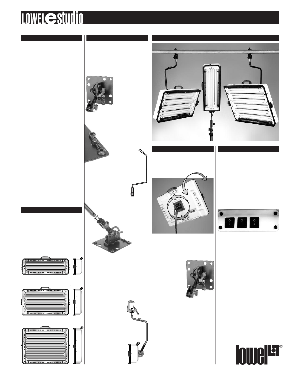
Models & Voltages
e-studio comes in 3 models housing
from 2-6 T-55 fluorescent lamps.
e-studio 2 & 4 model fixtures are available
in 120VAC or 240VAC versions. e-studio6
fixtures have auto-setting ballasts to work
with 120 - 240VAC. All e-studio fixtures
are non-dimmable.
e-studio2
e-studio4
e-studio6
e-studio™ Mounting
Mounting Plate
e-studio fixtures are sold in 2 mounting
configurations, with hardware to use on
a stand, or overhead on a lighting rail or pipe.
Stand mounting models use the Stand
Tilt-bracket; rail or pipe hanging use requires
the Overhead Mount Tilt-bracket. Both come
with the Mounting Plate
already attached to the
back of the fixture.
Whether you are using
the Stand Mount, or the
Overhead Mount,
familiarize yourself
with the Mounting
Plate before attaching the fixture to them.
The Mounting Plate has the ability to tilt the
fixture up & down, as well as rotate 180°.
If needed, it can be removed & rotated to
mount 4 ways on the fixture, depend-
ing on user preference. With the
fixture face down, remove the
plate by first using pliers to
remove the cotter
pin, and then use an
appropriate allen wrench to
loosen & remove the 4 corner screws.
Reposition the Mounting Plate, aligning it
with the 4 screw holes and the cotter pin
post. Attach & tighten the 4 screws securely,
before attaching the cotter pin
thru its post as shown.
Stand Mounting
Orient the Tilt-bracket post so that its
screw hole C lines up with the locking
knob D. Insert post and tighten
C
locking knob, checking to
make sure it is tightened
D
securely into the
screw hole.
Overhead Mounting
With the fixture laying face down on a table,
attach the Overhead Mount Tilt-bracket to
the Mounting Plate on its back. Overhead
Mounting models have a set screw replacing
the locking knob on the Mounting Plate
(see D in the image above). Similar to the
Stand Mounting description above, orient the
Tilt-bracket post so that its screw hole lines
up with the the set screw, and
tighten the screw securely
using an allen wrench. Attach
the fixture to the rail, tightening the large c-clamp bolt
securely with a wrench. Be
sure to retighten with a
wrench when positioned.
Attach one of the supplied Safety Cables
between the handle on the
fixture A and the safety cable
plate on the bracket B, and
another between B and the
pipe or rail.
B
A
Tilting & Pointing Controlling Light Intensity
Whether in stand mount or hanging clamp
configuration, the e-studio Tilt-bracket
& Mounting Plate combination is designed
to allow a complete range of fixture rotation
and tilting.
In stand mounting use, it will also place the
fixture’s center of gravity squarely over the
center of the stand for optimum balance.
Loosen the large Mounting Plate locking knob
A slightly to tilt the light on one axis
(up & down) and the
smaller locking knob B
to rotate the light on the
other axis (vertical vs.
horizontal placement).
Tighten locking knobs
to secure fixture
position.
Note: the smaller knob B has constant
tension locking and will hold its position
without additional tightening. Tightening
is only required for more permanent
positioning.
B
A
3 e-studio™ models
Light intensity is controlled through the
lamp switches on back of fixture.
The 120VAC models of e-studio2 & 4 have
separate switches for each lamp, and their
corresponding 240VAC models have lamps
that are switched in pairs.
All e-studio6 fixtures have lamps switched in
pairs. The e-studio6 lamps are switched from
the center pair to the outer most pair.
Page 2

Lowel e-studio™ Instructions
Lamps & Lamp Changes
The e-studio fixtures
use compact (55 watt)
fluorescent lamps.
®
Osram Studioline
(Manufacturer rated lamp life 8,000 hrs)
Designed for use in video & digital imaging
for higher output.
Tungsten CRI °K
FLS-55TU Studioline 55w/3200 85 3200
Daylight CRI °K
FLS-55DA Studioline 55w/5600 85 5600
Lamps
GE Cinema-Plus®Lamps
(Manufacturer rated lamp life 8,000 hrs)
Better lighting for film (still or motion picture)
due to better color rendering with film
emulsions. May require “minus green”
filtration gel (1/8).
Tungsten CRI °K
FLC-55TU GEF55BX/CINPLUS32 90+ 3200
Daylight CRI °K
FLC-55DA GEF55BX/CINPLUS55 90+ 5500
Lamp Changes
To change a lamp, remove any front
accessories, if attached. Remove the
screws attaching the metal endplates A.
A
*Note that the light-tube sockets are installed
on alternating ends of the fixture. To remove a
tube, gently grasp it by its glass end and
swing it slightly out from the fixture while
pulling it carefully from the socket.
Note: Take care when lifting lamps away from
the spring loaded retaining clips in the center
of the tube end of the lamp.
Replace lamps in same way, opposite order.
Be very careful as lamp-tubes are fragile and
can easily shatter. Read lamp mfr’s Warnings.
Fuse Change
e-studio fixtures come with a
user-replaceable mini fuse which
is installed in a small holder on the
same plate as the exterior AC power
socket. Access the fuse by removing
the cap with a small flathead
screwdriver. Swap fuse if necessary
and replace holder.
Fuse
See the Technical Specs chart below to find
the correct fuse rating for the e-studio model
& voltage that you are using.
Light Control Accessories
The following Accessories
can be attached to the
front of the fixture,
by opening the rotating
lock A sliding the
accessory into the top
& bottom slots on the
fixture face, and closing
the rotating lock.
Only one accessory
can be used at a time.
A
Intensifier
The mirrored Intensifier, when attached, can
almost double the light output of the fixture.
Assemble before attaching to light by placing
2 adjoining sides together at a right angle
& tightening screws. When both halves are
assembled, join them together and tighten
screws. Slide assembled intensifier into front
slot on fixture, close safety locks.
Note: Intensifier has grooved slot on front for
attachment of Honeycomb Grid to trim light.
Choose correct size of Honeycomb Grid.
Accessory Location Output Loss/Gain e-studio6 e-studio4 e-studio2
Barndoor Front of Fixture N / A FLS-620 FLS-420 FLS-220
Intensifier Front of Fixture + 80% FLS-622 FLS-422 FLS-222
Egg Crate Front of Fixture - 25% FLS-624 FLS-424 FLS-224
Honeycomb Grid Black 40° Front of Fixture - 25% FLS-634 FLS-434 FLS-234
Honeycomb Grid Black 30° Front of Fixture - 35% FLS-633 FLS-433 FLS-233
Honeycomb Grid Black 20° Front of Fixture - 54% FLS-632 FLS-432 FLS-232
Honeycomb Grid Black 40° Front of Intensifier - 30% FLS-644 FLS-444 FLS-244
Honeycomb Grid Black 30° Front of Intensifier - 22% FLS-643 FLS-443 FLS-243
Honeycomb Grid Black 20° Front of Intensifier - 46% FLS-642 FLS-442 FLS-242
Barndoors
For trimming spill of the light, slide
Barndoor assembly into slot on fixture,
and secure locks. Open doors and adjust
for proper trimming of spill. Do not operate
unit with Barndoors closed.
Egg Crates
for controlling spill. Slide the Egg Crate into
the front accessory slot. Less control than
Honeycomb Grid, with less output loss.
Honeycomb Grid
Each fixture has 2 options for using
honeycomb grids to control the spill of
the light, either placing the grid on the front
of the fixture, or attaching it to the front
of the Intensifier. It is not possible to use
the “front of fixture” grid with the Intensifier.
The grids are available in black with 20, 30,
or 40 degree dispersion. Honeycomb Grids
cause some loss of light output (see chart).
Note: e-studio fixtures have installed
Gel Clips. For using colored or diffusion gels
in front of the fixture. Attach pre-cut gel
material to the 4 spring clips on the corners
of the front reflector plate
(approx) (Code) (Code) (Code)
Technical Specs Repairs & Info
Amperage: See charts, for models operating at 120VAC or 240 VAC 50/60 Hz.
Fuse Ratings/Classement des fusibles: 50/60Hz
Power Factor: >.99
120v e-studio2, 4
Model Voltage Continuous Power Peak Current Fuse Rating
e-studio2 120 VAC 0.8 1.3 3.15 A
e-studio4 120 VAC 1.7 2.5 5 A
230v e-studio2, 4
Model Voltage Continuous Power Peak Current Fuse Rating
e-studio2 230 VAC 0.4 0.6 2.5 A
e-studio4 230 VAC 0.8 1.3 3.15 A
120 - 230v e-studio 6 (when auto-setting to 120VAC or 230VAC, the below values apply)
Model Voltage Continuous Power Peak Current Fuse Rating
e-studio6 120 VAC 2.4 3.5 5 A
e-studio6 230 VAC 1.3 1.9 5 A
Repairs, problems, suggestions
and requests for brochures/catalogs,
instructions and parts lists can
be handled through your Authorized
Lowel Dealer/Distributor or directly
through Lowel. Electrical repairs
should be made only by Lowel
or by a qualified electrician.
Lowel-Light
Manufacturing, Inc.
90 Oser Avenue, Hauppauge, N.Y. 11788
Call: 800 645-2522 or 631 273 2500
e-mail: info@lowel.com
www.lowel.com
255 ver. 2.0 © 2009, Lowel-Light Mfg., Inc.
 Loading...