

Page 1
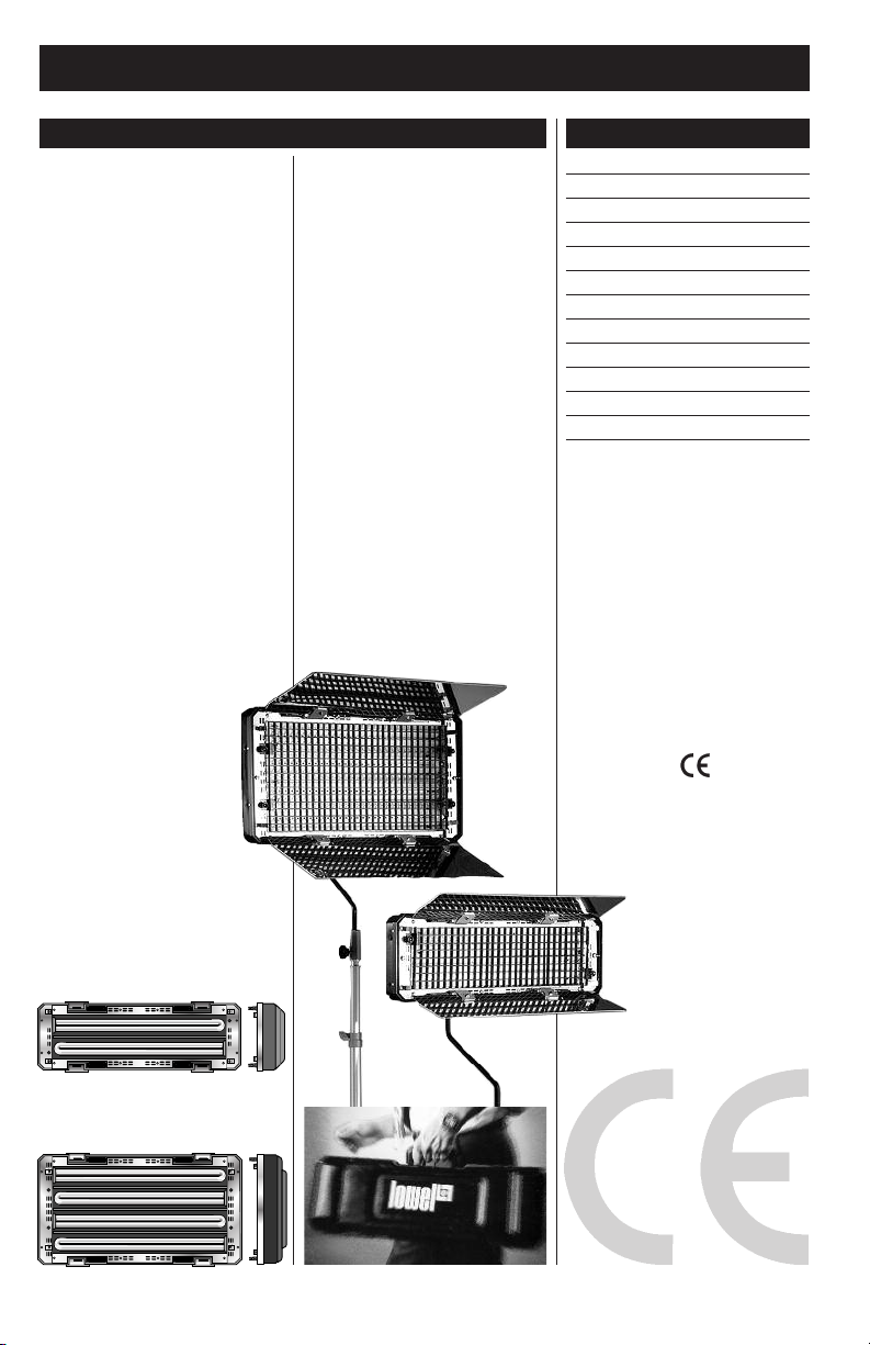
The Lowel Caselite is a professional lighting system. Read
these instructions and lamp manufacturers’ warnings before operating.
n Do not leave Caselite unattended.
For non-stationary (portable
location) use.
n Not for household use. Use only
for photo graphic lighting(video &
film imaging).
n Do not exceed maximum rated
wattage for unit.
n Use maximum 55 Watt lamps.
n Always unplug unit before relamping.
n Be sure lamp is securely seated
in lamp socket.
n Do not use near standing water.
n Internal ballast produces high
start-up voltage.
n Never bypass plug’s ground pin.
n Do not interfere with unit’s
ventilation.
Lowel Caselite®Instructions
General Warnings Contents
n When attaching to overhead pipes
or grids, always use a Safety Cable.
n Do not attempt to open unit,
no user serviceable parts inside.
See p. 6 for fuse change.
n This is a portable location light.
It complies with UL 1573for still
photographic lights when used with
the supplied T1-80 cable. For use as
a portable stage lighting unit use
with Lowel T1-808 10’ unswitched
cable rated for ‘hard service’.
Fluorescent Warnings
n Avoid looking directly at the tubes
for extended periods of time.
n Fluorescent tubes contain highly
poisonous mercury.
n In the event of lamp breakage,
avoid contact with broken pieces.
n Read lamp manufacturers
information fully.
Opening the Unit 2
Stand Mounting 2
Tilting & Pointing 2
Controlling Light Intensity 3
Fuse Change 3
Lamps & Lamp Changes 3
Light Controls 4
Barndoor/Intensifiers 4
Egg Crates 4
Gel Clips 4
Closing/Transporting 4
Problems, Repairs & 4
LOWELCASELITE4
LOWELCASELITE2
MODEL
Caselite 2 Uses 2 lamps
Caselite 4 Uses 4 lamps
Page 2
Caselite®Operations
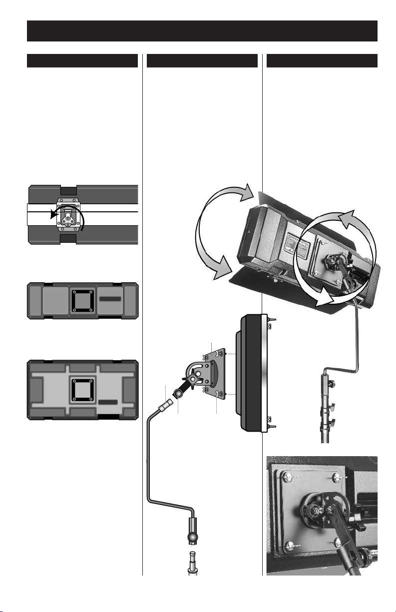
Opening the Unit Stand Mounting Tilting & Pointing
Laying the Caselite down, with its rear
mounting adaptor facing up, release
the twist-locks and lift the fixture half
straight up off the lid half. Lay the
fixture down with its exterior facing up.
Release the interior flap locking straps
on the lid to allow opening of the
storage compartment. Remove the
Mounting Plate, Stand-fitting Tilt-bracket (& Uni Sr. Stand, if stored in lid).
Caselite 2
Caselite 4
With the Caselite fixture face down,
attach the mounting plate C to the
adaptor receptacle in the center of the
fixture, as shown. Turn the 4 twist-lock
knobs D to lock the plate firmly to the
fixture. Mount Stand-fitting Tilt-bracket
A onto stand (5/8” stud) and tighten
knob E. Loosen large locking knob B
on Mounting Plate, lift Caselite and
insert stud end of stand fitting bracket A
into Mounting Plate fitting. Note that
the Tilt-bracket stud has a
safety indent cut into
it. Make sure to line
up the Mounting
Plate knob so
that its screw
will tighten into
the indent, for
most secure
mounting. Tighten
B sufficiently. If you
are attaching Caselite
Mounting Plate to a grip arm or
boom, be sure to tighten sufficiently
and use a larger stand with
counter balance weight
to retain stability.
C
The Stand-fitting Tilt-bracket is
designed to place the fixture’s center
of gravity squarely over the center of the
stand, while allowing a complete range
of rotation and tilting. With the fixture
mounting plate tightly mounted to the
Tilt-bracket, loosen the large locking
knob slightly to tilt the light on one
axis (up & down) and the smaller
locking knob to rotate the light on
the other axis (vertical vs horizontal
placement). Tighten both locking
knobs to secure fixture position.
A
B
E
D
2
Page 3

Caselite®Operations
Light intensity is controlled through
the lamp switches. In each CE model
Caselite, the AC to the fixture is controlled by a switch on the power cable,
and then the lamps are controlled in
pairs by switches on the back panel.
A To turn the fixture on, Click the
power switch on the AC cable.
B Operate the switches on the back
of the unit to turn the lamp pairs on.
By using these switches, you will be
able to control light intensity level.
(Caselite2 has one switch to control
its 2 lamps)
Lamps
The Caselites use compact (55
watt) fluorescent lamps.
GE Cinema-Plus®Lamps
(Manufacturer rated lamp life 8,000 hrs)
Better lighting for film (still or motion
picture) due to better color rendering
with film emulsions. May require
“minus green” filtration gel (1/8).
Tungsten CRI °K
FLC55-TU Cine-Plus 55w/ 90+ 3200
Daylight CRI °K
FLC55-DA Cinema-Plus 55w 90+ 5500
Osram Studioline
®
Lamps
(Manufacturer rated lamp life 8,000 hrs)
Designed for use in video & digital
imaging for higher output.
Tungsten CRI °K
FLS-55TU Studioline 55w/3200 85 3200
Daylight CRI °K
FLS-55DA Studioline 55w/5600 85 5600
Controlling Light Intensity
Caselite 2 Switch
Caselite 4 Switches
Lamps & Lamp Changes
Lamp Changes
To change a lamp, remove the plastic
eggcrate (if attached) by releasing the
snap-locks on each end. Remove both
metal endplates by turning the twistlocks (see illus.). Note that the lighttube sockets are installed on alternating
ends of the fixture. To remove a tube,
gently grasp it by its glass end and
swing it slightly out from the fixture
while pulling it carefully from the socket. Replace lamp in same way, opposite
order. (Be very careful as lamp-tubes
are fragile and can easily shatter. Read
lamp mfr's
Warnings).
Fuse Change
The Caselites come with a user-replaceable mini fuse which is installed in
a small holder on the same plate as
the exterior AC power socket.
Access the fuse by removing the cap
with a small flathead screwdriver.
Swap fuse if necessary and
replace holder.
Caselite2 CE model
uses fuses rated at 2.5 Amps and
250 Volts.
Caselite4 CE model
uses fuses rated at 3.15 Amps and
250 Volts.
Voltage Selector
& Fuse Change.
The CE model has an auto voltage
setting ballast. The Caselite will set
itself automatically from 120 - 240v.
Fuse
3
Page 4

Lowel Caselite®Instructions
Light Controls Closing/Transporting
Barndoor/Intensifiers
The dual purpose Barndoor/Intensifiers
add versatility & output to the Caselite.
With the mirror-finish Intensifier side
facing in towards the lamps, output
can be increased by approximately
40% depending on door positioning.
The black Barndoor side can be
useful in trimming the spill & output
of the fixture.
To reverse the doors, open them fully &
loosen the twist-locks on the black side.
Slide the barndoor/intensifier straight
out to remove. Flip the door & reinstall,
turning the twist-locks to retighten.
Egg Crates
Caselite comes with a detachable plastic
egg crate attached to the inside flap of
the storage lid. It can be very usefu in
controlling spill of the light, with some
loss of output. To remove, flip the
release levers on each end of the
egg crate and carefully remove. Snap
egg crate onto fixture in front of lamps.
Gel Clips
Gel Clips are installed on each end
of the fixture to hold gel pieces
cut to the size of the lamp area.
Use enclosed Lowel Gel-jaws clips
when attaching a larger piece of
diffusion material to the outside edges
of the Barndoor/ Intensifiers to further
soften the light.
Note: by doing this you are creating a
larger, and therefore softer, light-source.
Problems, Repairs &
Repairs, problems, suggestions
and requests for brochures/
catalogs, instructions and parts
lists can be handled through your
Authorized Lowel ealer/Distributor
or directly through Lowel.
Electrical repairs should be
made only by Lowel or by
a qualified electrician.
Caselites are designed and manufactured by Fluo-Tec, Mexico in collaboration with Lowel-Light Mfg., Inc.
Replace eggcrate, if used, on the lid flap
and snap its locks into the retaining
holes. Fold Barndoor/Intensifiers in
towards lamps. Loosen stand fitting
at stand and remove unit & bracket
from stand, laying fixture face down
on a table/floor. Loosen large locking
knob and remove the stud end of the
Stand-fitting Tilt-bracket. Turn the
4 twist-lock knobs to unlock the
Mounting Plate from the fixture and
remove it. Place both Mounting Plate,
Stand-fitting Tilt-bracket inside lid compartment, taking care that it will fully
close. (If using kit version, place Uni Sr.
Stand in lid also), See illus. below for
most efficient packing order. Secure
storage lid flap with locking straps.
Laying the lid on its back, replace
fixture on top and close the twist-lock
brackets, turning them to securely lock
the Caselite closed. If transporting the
unit in rainy weather, use the optional
rain cover to prevent leakage.
Note unit is not waterproof, avoid leaving closed unit exposed to rain or
excessive dampness.
ver 2.2© 2010, Lowel-Light Mfg., Inc.
Lowel-Light Manufacturing, Inc.
90 Oser Avenue,
Hauppauge, NY 11788
Call: 800 645-2522
e-mail info@lowel.com
www.lowel.com
4
261
 Loading...