

Page 1
P/N: LIT-816790
Rev. B
Page 2

Steadimate Operator's Manual
Rev. B
P/N: LIT-816790
Steadicam® and Steadimate
Other trademarks are the property of their respective owners.
All specifications stated within this manual are subject to change without notice.
© 2016 The Tiffen Company. Written by E. Barthelman.
®
are trademarks of The Tiffen Company.
Page 3

Table of Contents
A Word from Garrett Brown 1
The Steadimate System 2
Steadimate Components 2-1
Setting Up 3
Preparing the Steadimate 3-1
Installing the Steadimate 3-2
Balancing 4
Upright or Inverted? 4-1
Upright Mode: Centering 4-2
Upright Mode: Balancing 4-3
Inverted Mode: Centering 4-4
Inverted Mode: Balancing 4-5
The Steadicam Vest 5
Fitting the Vest 5-1
The Steadicam Arm 6
Connecting the Arm and Vest 6-1
Steadimate Operating 7
Lifting the System & Adjusting the Arm 7-1
Check your Threads 7-2
Operating Modes, Tips & Tricks 7-3
Accessories 8
Maintenance and Cleaning 9
Contact Tiffen 10
Page 4

A Word from Garrett Brown
Hello and congratulations on your new Steadimate®. You’re now equipped to ‘fly’ your motorized
stabilizer on a Steadicam® arm and vest; so get set for a new, ‘hybrid’ experience.
If you’re a longtime Steadicam operator who now has occasion to carry around a MōVI
Ⓡ
or RONINTM,
the Steadimate restores the weightless, fingertip moves you’re used to: those graceful translations
in space that are nearly impossible when your outstretched arms are heavily burdened.
If you’re already a MōVI/RONIN owner/operator, welcome to our world! You’re in for a treat— a
taste of what Steadicam aces have known and enjoyed for decades. Not just angular stability and
classically smooth moves, but a chance to tirelessly ‘operate’ moving shots with improved precision
and style.
Motorized gimbals have uncanny roll stability and anyone can pick one up and instantly move it
around. But of course the stabilizer mechanism plus camera, lens, battery, etc. must be held out in
front and moved through space by your heavily loaded arms—often for minute after minute—and
the increasing fatigue can make your work look jerky and irregular as you pass foreground objects.
Steadimate floats your gimbal like a Steadicam sled, so the inherent inertia of the rig in space is
fingertip detectable and your booming and traveling moves are Steadicam smooth. In addition,
Steadimate is the only support mechanism that is neutrally balanced in two isolated axes for
effortless pan and tilt (all others make the rig extremely bottom heavy and tough to tilt).
If you’re operating solo, in what MōVI calls ‘Majestic’ mode—without a second person controlling
camera angle by joystick or wheels—the mushy operating initiated by the support handles can now
be significantly improved. With Steadimate, you can tighten the tuning parameters so your pans and
tilts are more instantaneous and precise, like the dynamic and responsive operation that Steadicam
is known for.
So enjoy your new Steadimate! It will not only relieve up to 25 lb. of outstretched burden, it will
smooth the spatial component of moves as well as the angular bit that gimbals do so well.
…and don’t forget to read The Steadicam Operator’s Handbook by Jerry Holway and Laurie Hayball,
with its vast amount of moving camera lore to help you accomplish what we all strive for—to make
effective and memorable shots!
Best,
Steadicam® Inventor
Philadelphia USA
1
Page 5
1.1
Page 6
The Steadimate System
Motorized Gimbal
The Steadimate fits motorized
gimbals with 25 mm, 25.5 mm,
or 30 mm diameter handlebars
The Vest
Adjustable to fit most operators
Provides connection to the Arm
The Arm
Supports the Steadimate System
Isolates camera from operator
The Steadimate
Links The Arm to motorized gimbal
Allows fingertip control
The Steadicam Steadimate is the link between motorized gimbals and the traditional
Steadicam Arm and Vest. Together, the Steadimate System provides additional stabilization
and neutrally balanced tilting which result in smoother shots and less work for the operator.
2
Page 7
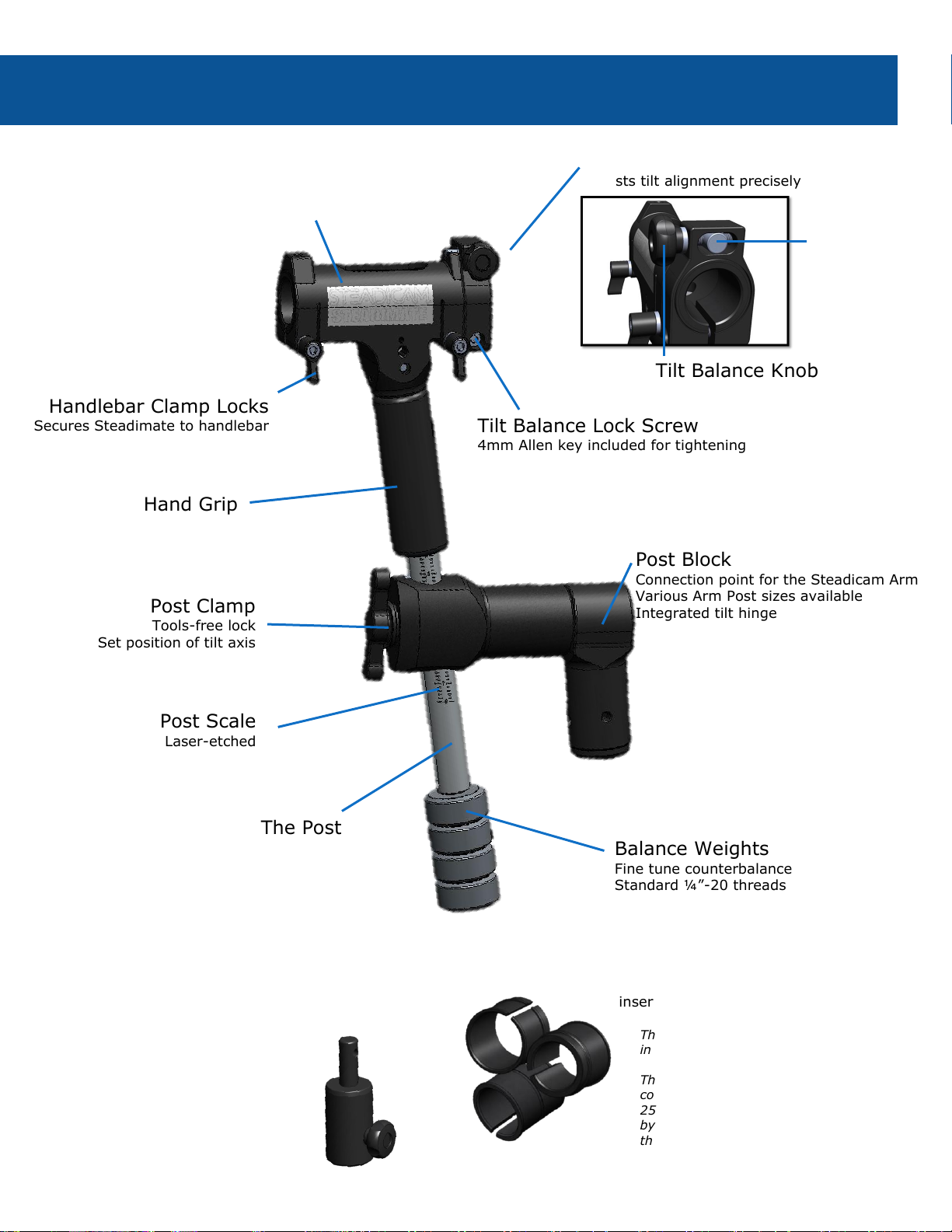
Steadimate Components
Hand Grip
Tilt Balance Knob
Balance Weights
Fine tune counterbalance
Standard ¼”-20 threads
Post Clamp
Tools-free lock
Set position of tilt axis
Handlebar Clamp Locks
Secures Steadimate to handlebar
Post Scale
Laser-etched
Post Block
Connection point for the Steadicam Arm
Various Arm Post sizes available
Integrated tilt hinge
Handlebar Clamp
Attaches Steadimate to handlebar of
your motorized gimbal
Tilt Balance Lock Screw
4mm Allen key included for tightening
Clamp Inserts
25 mm, 25.5 mm, and 30 mm
inserts included
The 30 mm insert comes installed
in the handlebar clamp.
The 25 mm and 25.5 mm inserts
come in the Steadimate box, the
25.5 mm inserts are distinguished
by the debossed line running
through the middle.
Balance Pin
Install on top of tuning stand
Verify system balance
Tilt Balance Mechanism
Adjusts tilt alignment precisely
The Post
Balance Nut
2-1
Page 8
Setting Up
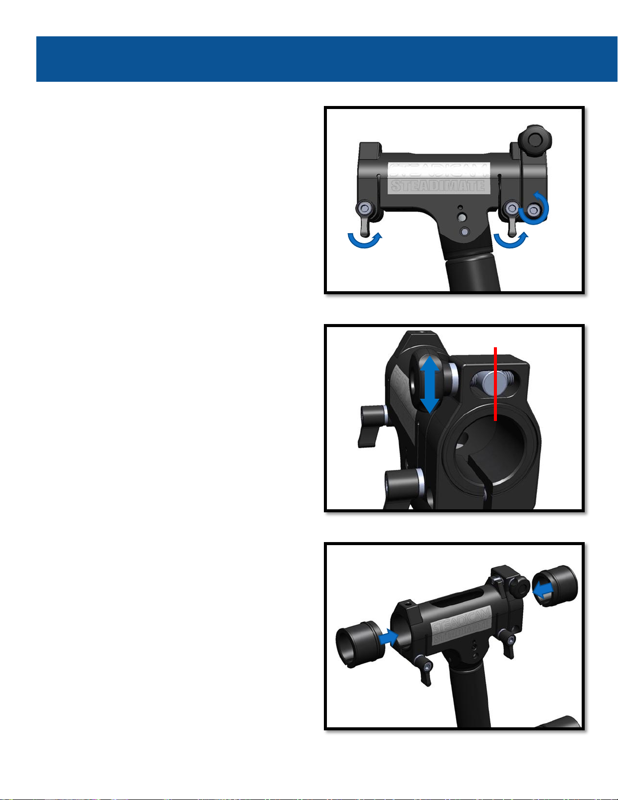
Prepare the Steadimate:
Loosen the Handlebar Clamp Locks
and Tilt Balance Lock Screw.
Center the Balance Nut within the Tilt Balance
Mechanism by turning the Tilt Balance Knob.
This gives us the maximum range of
adjustability in either direction.
You may need to turn the Knob in either
direction, depending on how the Steadimate
was stored.
Take a moment to confirm that the Clamp
Inserts are correctly sized for your motorized
Gimbal. They’re designed to fit 25 mm, 25.5
mm or 30 mm handlebars.
With the Clamp Locks and Lock Screw loose, the
Inserts simply snap in place.
3
Page 9
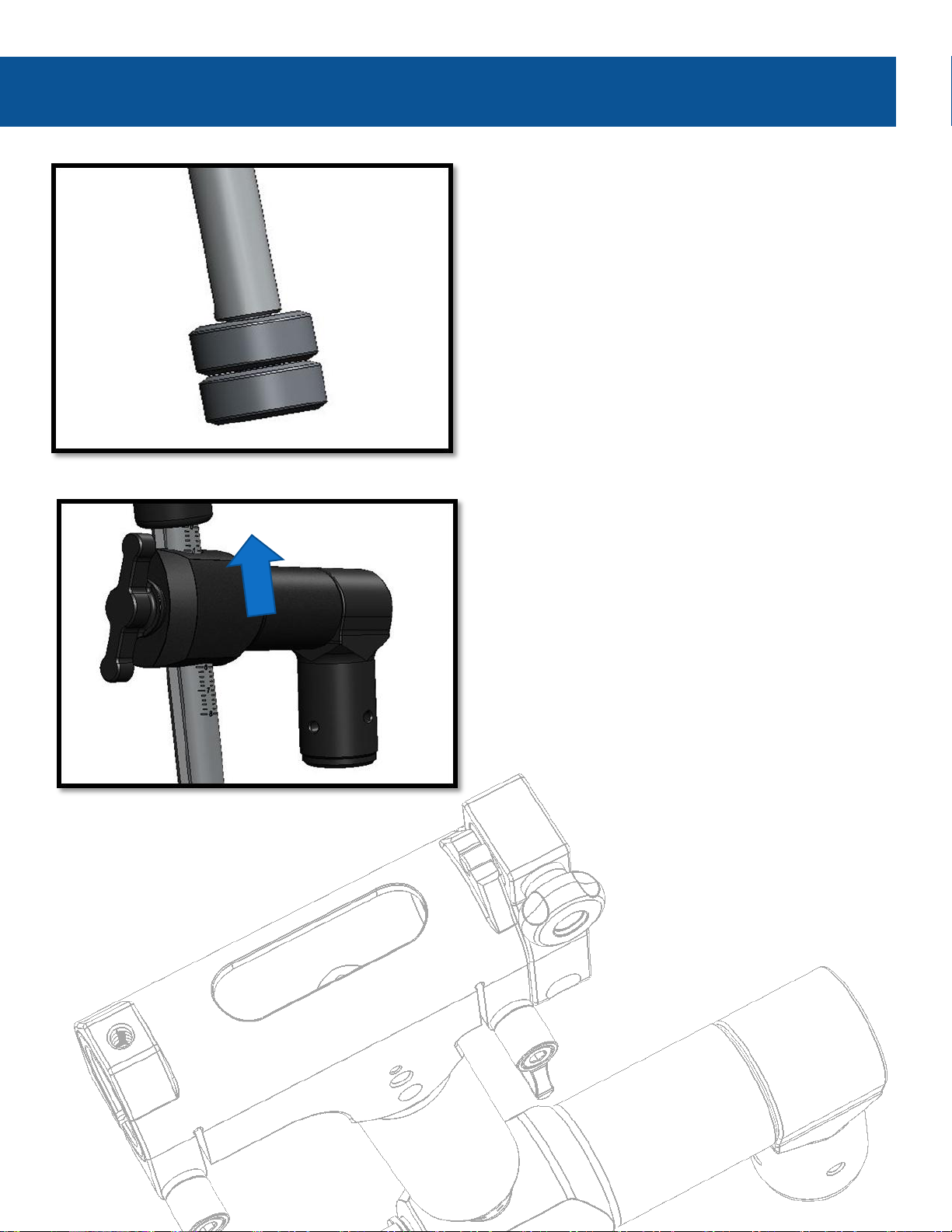
Preparing the Steadimate
Loosen the Post Clamp and slide it all the way
up until it reaches the 0 position and then
retighten the Post Clamp.
Caution: Only adjust the Post Block position
while the system is on the tuning stand. Never
loosen the Post Clamp while balancing or while
the Steadimate is mounted on the Arm.
Install two Balance Weights at the bottom of
the Steadimate Post.
The weights can be used for fine-tuning the
top-to-bottom or tilt center of gravity (CG) of
the Steadimate later; great when adding or
removing small accessories or swapping
lenses.
3-1
Page 10
Setting Up
Is your motorized gimbal dialed in?
Proper setup of your motorized gimbal is critical to accurately balancing the Steadimate
System. Refer to the manual from your motorized gimbal manufacturer for directions on
proper tuning. Test handheld in single operator mode before going any further.
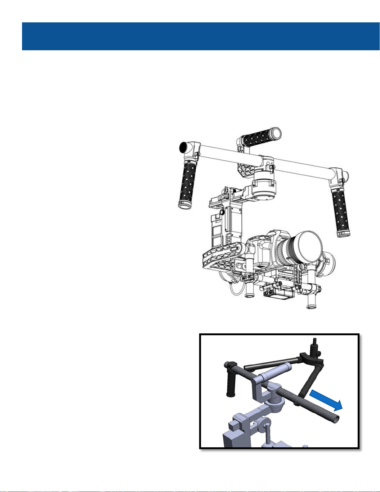
With the motorized gimbal resting on the
tuning stand, remove the right side handle.
Note: If you prefer operating a Steadicam in
Goofy Mode, you may choose to remove the
left handle and install the Steadimate on the
left side, instead.
Add ALL required accessories and build
a compact setup without loose
components. We’ll be balancing the
entire Steadimate System, not just the
camera.
Keep heavy accessories, like batteries,
close to the Steadimate Handlebar
clamp so the weight is well supported.
Caution: placing excessive weight far
from the Steadimate Handlebar Clamp
could over-stress the carbon fiber tube.
3-2
Page 11

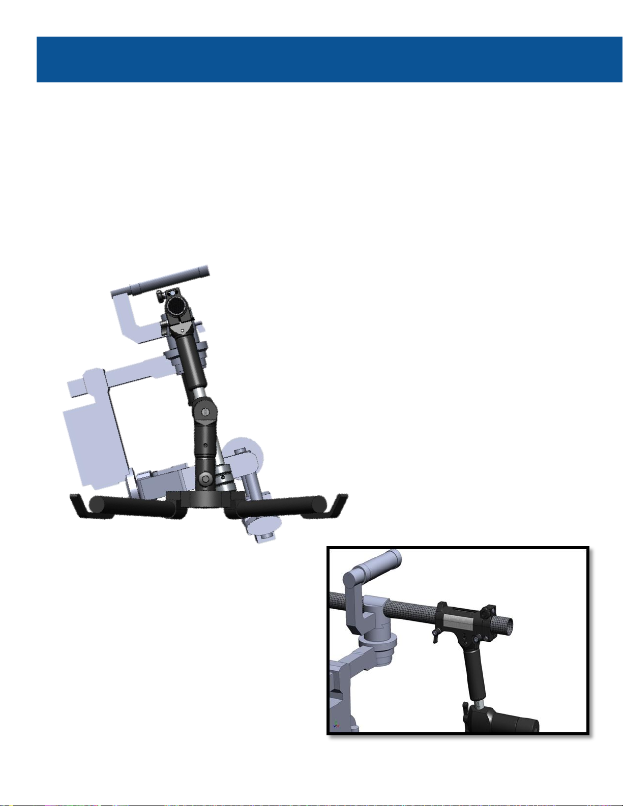
Installing the Steadimate
From the profile, visually align the Steadimate
with the central axis of the pan motor. The
Steadimate should be parallel to the vertical
surfaces of the motorized gimbal when
everything is centered.
Just get it close, we’ll be using the Tilt Balance
Mechanism to fine tune this in the Balancing
section soon.
Slide the Steadimate onto the handlebar in
place of the handle.
Note: For optimum performance and safer
operation, keep the space between the
Handlebar Clamp and the base of the pan
motor as narrow as your build will allow.
Tighten the Handlebar Clamp Locks by hand
and securely tighten the Tilt Balance Lock
Screw with the included 4 mm Allen key.
Caution: the Tilt Balance Lock Screw should
be tightened forcefully, especially for heavier
setups, to ensure the Steadimate Handlebar
Clamp is secured to the handlebar
3-2.1
Page 12
Balancing
Upright or Inverted Mode?
With the motorized gimbal powered,
place the Post Block on the Balance Pin
so the Steadimate System is free to
move and not contact anything.
Keep a hand on the Steadimate grip
and observe its balance behavior.
Balancing the Steadimate system for the first time requires patience and attention to
detail, just as you experience while setting up a motorized gimbal or traditional Steadicam for
the first time. Read through the process and take your time.
Note: always balance the Steadimate with the motorized gimbal powered on and performing
properly.
Tilt the camera down and note the
angle at which the Steadimate comes
to rest. Then tilt up to see what the
“balance window” angle is between
the two resting points.
Also check to see if the Steadimate
will stay parked vertical when the
camera is exactly level.
4
Page 13
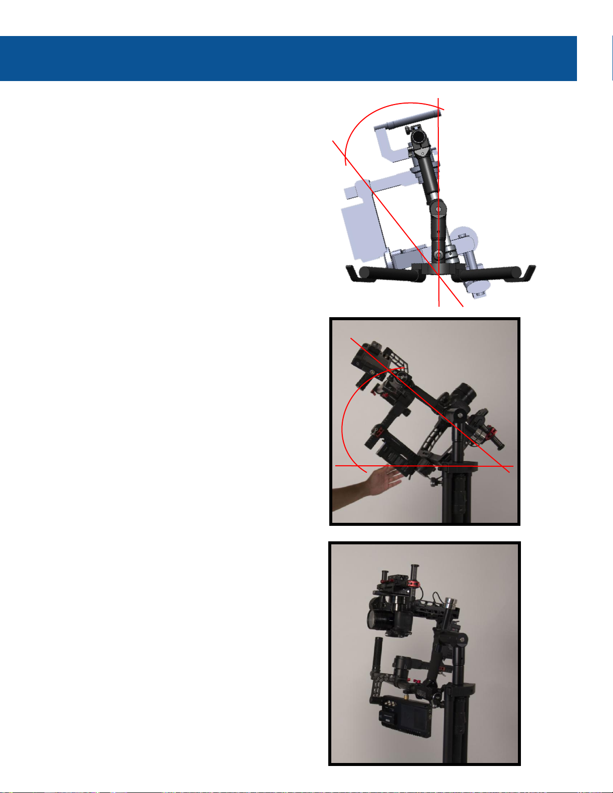
Upright or Inverted?
If the Steadimate remains upright, within
0-45˚ of vertical, you’ll be balancing in
Upright Mode. Most setups will be upright, just
like operating a traditional motorized gimbal.
Flip to the next page to start Upright Mode
Balancing.
If the Steadimate is between 45˚ and
horizontal, confirm that the Post Clamp is set
at number 0 and try adding 2 more Balance
Weights. You may also remove or change your
accessories to lighten the system.
If the changes you make achieve an upright
Steadimate, then go on to the next page.
However, if the Steadimate is still more than
45˚ from vertical, you’ll balance in Inverted
Mode, starting on page 4-4.
If the Steadimate is truly inverting, where the
Handlebar is below the Post Block, then you must
balance in Inverted Mode.
This is most common when using heavy monitors
with lightweight motorized gimbals or when larger
accessories are placed high on the top handlebar.
Jump to page 4-4 for Inverted Mode balancing.
4-1
VERTICAL
45°
HORIZONTAL
45°
Page 14
Center the Steadimate:
With the rig on the Balance Pin, hold the Steadimate
handle vertical and loosen your grip to test whether it
will remain vertical on its own, or if it tries to tilt fore
or aft. Usually, the Steadimate will tilt one way or the
other.
Your motorized gimbal is still powered on, right?
The Steadimate has two adjustments which we use to balance the Steadimate system; the
Tilt Balance Knob and the Post Clamp. The Tilt Balance adjustment enables us to precisely
center the Steadimate with the motorized gimbal along the vertical axis. And by adjusting the
location of the Post Clamp on the Post, we can place the center of gravity of the motorized
gimbal just below the tilt axis of the Post Block. The goal is to make the system tilt and pan
with fingertip control. Let’s get started!
Balancing
While still on the Balance Pin, hold the
Steadimate handle vertical and loosen the two
Handlebar Clamp Locks.
Note: DO NOT loosen the Tilt Balance Lock
Screw. It will act as a safety and works with
the Tilt Balance Mechanism in the next step.
4-2
Page 15

Now re-tighten the Clamp Locks.
Note: For heavier setups, use the 4 mm Allen
Key Wrench to tighten the clamp locks rather
than hand tightening. This will allow you to
forcefully secure the Handlebar Clamp to the
handlebar.
Turn the Tilt Balance Knob in either direction
until the handle stays vertical. The direction
you turn depends on which side the
Steadimate is tilting.
You’ll be able to feel the weight on the grip
getting lighter when you turn the correct
direction.
When you’re close, try letting go completely to
make sure the Steadimate remains perfectly
vertical.
Upright Mode: Centering
4-2.1
Note:
It should not be necessary to loosen the Tilt Balance Lock Screw unless your initial alignment
was way off.
Always return the System to the tuning stand before loosening the Tilt Balance Lock Screw to
realign the Steadimate on the handlebar.
Page 16

Balancing
The next step is where the magic happens. By moving the Post Block down the Post, we can
adjust where the system’s center of gravity is located relative to the Steadimate pivot. We
use a simple method of guess and check to find that sweet spot. The lighter we can make the
tilt axis, the less work you have to do tilting and the better isolated the camera will be from
the operator’s walking motion. If you’re a Steadicam Operator, this is equivalent to setting
your Drop Time.
Set the balance:
Try tilting the Steadimate to aim the camera
lens toward the sky. Does it tilt with fingertip
control, or is it heavy?
Note: we’ll be testing the balance of the
system on the Balance Pin, but doing
adjustments on the tuning stand. Then
repeat until it’s perfect.
If your Steadimate System is light to the touch
and comes to rest within a 45˚ tilt window,
congratulations! You’re ready to rock the new
Steadimate.
Most of the time, however, you’ll need to adjust
the Post Block height to find that perfect setup.
4-3
0° - 45°
Page 17

Upright Mode: Balancing
If the tilt behavior is heavy, that means your system is too bottom heavy.
But instead of removing the weights, which you can use later for fine-tuning, we’ll move the
Post Block down the Post.
Dock the Steadimate System on the tuning stand.
Loosen the Post Clamp and slide the Post
Block one number down the Post scale and retighten the Post Clamp.
With more Steadimate experience, you’ll gain
a sense for how far to move the Post Clamp.
Until then, let’s move one increment at a time.
Return the Steadimate to the Balance Pin and
test tilt the system.
Find the resting points for tilting up and down
and make sure they are within the 45˚ tilt
window.
Repeat the last two steps until the tilting effort
is very light. You’re looking for fingertip
control.
4-3.1
Page 18

The closer your balance is to perfect, the more
sensitive the Tilt Balance becomes.
Check that the system can remain vertical
with a light touch. Is it tilting slightly again?
If necessary, go back and re-center the
Steadimate using the Tilt Balance Knob as
previously described on page 4-2 of this manual.
If you lower the Post Clamp too far, you’ll find
the tilt window increasing beyond the ideal 45˚
included angle or going horizontal.
Simply revert back to the previous Post Scale
setting that worked well.
Balancing
4-3.2
Page 19

After repeating these steps a few times, you’ll
have found that ideal balance which reduces
tilt and panning effort also further isolates
your camera.
Now skip on ahead to page 5 to learn about
the Vest and Arm.
With the Post Block height set
correctly, you can later add or remove
weights when accessories, lens swaps
or personal preference require small,
quick changes to the CG of the system.
Upright Mode: Balancing
4-3.3
Page 20

Balancing
The Steadimate has two adjustments which we use to balance the Steadimate system: the
Tilt Balance Knob and the Post Clamp. The Tilt Balance adjustment enables us to precisely
center the Steadimate with the motorized gimbal along the vertical axis. Adjusting the
location of the Post Clamp along the Post enables us to place the center of gravity of the
motorized gimbal just below the tilt axis of the Post Block. The goal is to make the system tilt
and pan with fingertip control. Let’s get started!
Prepare for Inverted Mode:
Reverse the motorized gimbal camera mount
at the handlebar so the camera will be
pointing away from you.
Adjust the Post Clamp height to
number 5 on the Post Scale, this will
make the system more top heavy but
we’ll dial it in soon.
4-4
Page 21

Inverted Mode: Centering
Center the Steadimate:
Place the system on the Balance Pin and hold
the Steadimate handle vertical. Slowly loosen
your grip to test whether it will remain vertical
on its own, or if it tries to tilt fore or aft.
Usually, the Steadimate will tilt one way or the
other.
Your motorized gimbal is powered on, right?
Tilt your monitor for ease of viewing
with the handlebar at the bottom.
4-4.1
Page 22

Balancing
While still on the Balance Pin, hold the
Steadimate handle vertical and loosen
the two Handlebar Clamp Locks.
Note: DO NOT loosen the Tilt Balance
Lock Screw. It will act as a safety and
works with the Tilt Balance Mechanism
in the next step.
Note:
It shouldn’t be necessary to loosen the Tilt Balance Lock Screw unless your initial alignment
was way off.
Always return the System to the tuning stand before loosening the Tilt Balance Lock Screw
to realign the Steadimate on the handlebar.
Turn the Tilt Balance Knob one way or the
other until the handle stays vertical.
You’ll be able to feel the weight on the grip
getting lighter until it is centered. Try letting
go completely to make sure the Steadimate
remains perfectly vertical.
Now re-tighten the Handlebar Clamp Locks.
4-4.2
Page 23

Inverted Mode: Balancing
The next step is where the magic happens. By moving the Post Block up or down the Post,
we can adjust where the system’s center of gravity is located relative to the Steadimate pivot.
The good news is that we use a simple method of guess and check to find that sweet spot.
The lighter we can make the tilt axis, the less work you have to do tilting and the better
isolated the camera will be from the operator’s walking motion. If you’re a Steadicam
operator, this is equivalent to setting your Drop Time.
Set the balance:
Try tilting the Steadimate to aim the
camera lens toward the sky. Does it tilt
with fingertip control, or is it heavy?
This time, we’ll be testing the balance of
the system on the Balance Pin, but
doing adjustments on the tuning stand.
Then repeat until it’s perfect.
If your System is light to the touch and
comes to rest within a 45˚ tilt window,
congratulations! You’re ready to rock
the new Steadimate.
Most of the time, however, you’ll need
to adjust the Post Block height to find
that perfect setup.
4-5
Page 24

If the tilt behavior is heavy, that means your system is too bottom heavy. But instead of removing the
weights, which you can use later for fine-tuning, we’ll move the Post Block down the Post.
Dock the Steadimate System on the tuning stand.
Loosen the Post Clamp and slide the Post Block one number down the Post scale (i.e. if you’re at 5
move down to post scale mark 4) and re-tighten the Post Clamp.
With more Steadimate experience, you’ll gain a sense for how far to move the Post Clamp.
Until then, let’s move one increment at a time.
Return the Steadimate to the Balance Pin and test tilt the system.
Find the resting points for tilting up and down and make sure they are within the 45˚ tilt window.
Repeat the last two steps until the tilting effort is very light. You’re looking for fingertip control.
Balancing
4-5.1
Page 25

The closer your balance is to perfect, the
more sensitive the Tilt Balance becomes.
Check that the system can remain vertical
with a light touch. Is it tilting slightly
again?
If necessary, go back and re-center the
Steadimate using the Tilt Balance Knob as
previously described on page 4-2 of this
manual.
If you lower the Post Clamp too far,
you’ll find the tilt window increases
beyond the 45˚ included angle.
Simply revert back to the previous Post
Scale setting that worked well.
Inverted Mode: Balancing
4-5.2
Page 26

Balancing
After repeating these steps a few
times, you’ll have found that ideal
balance which reduces tilt and
panning effort also further isolates
your camera.
Now we’ll learn all about the Vest
and Arm.
With the Post Block height set
correctly, you can later add or remove
weights when accessories, lens swaps
or personal preference require small,
quick changes to the CG of the system.
4-5.3
Page 27

Inverted Mode: Balancing
4-5.4
Page 28

Velcro Straps
Wide range of adjustability
The Steadicam Vest
The Steadicam Vest is the major connection between your body and the Steadimate
System. It’s adjustable to fit most body types via Velcro straps and micro-adjustable buckles.
Just like setting up the Steadimate, taking your time to properly fit the vest will ensure you
get the highest performance and most comfort out of the system.
Shoulder Pads
Shoulder Connector
Socket Block
Interface for the arm
Adjustable height
Hip Pads
Adjustable buckles
Chest Straps
Adjustable buckles
Note: If you already have a Steadicam kit, you can use your Vest and Arm with the Steadimate. Just
get the correct Insert for the Post Block to match your Arm Post and you’re ready!
Hip Strap
With lower back padding
Adjustable Velcro and buckles
Center Spar
Adjustable vest length
Thumbscrew Bolts
Fore/Aft alignment
General Components of
a Steadicam Vest:
5
Page 29

Fitting the Vest
Proper Vest fit:
The length of the Vest
should place the waist low
over the hip bones yet still
allow your legs to lift for
climbing stairs.
The Center Spar should
stay centered on your torso
and not slip to either side.
The Shoulder Connectors
should not ride high and the
Shoulder Pads should rest
on your shoulders.
The fit should be very snug
but not straightjacket tight.
The Socket Block should
move with you and not shift
under load.
When adjusting Velcro
straps, keep them
symmetrical across the
back and waist.
It can be helpful to have a
friend assist you when
fitting the vest for the first
time. If you don’t have
someone to assist you, a
full length mirror also
works.
1. Open all buckles on the left
side of the vest and slip on
the vest.
2. Close the Shoulder
Connector.
Leave all other buckles open
until instructed to close them
in the fitting process.
3. Connect the chest straps
and center the Chest
Plate on your chest.
4. Pull down on the Chest
Plate to seat the shoulder
pads on your shoulders.
5. Adjust the overall Vest
length so the Hip Pads are
centered over your hips.
6. Be sure the Hip Straps are
horizontal on the Pads and
tighten them evenly.
7. Push down on the Vest to
ensure it is centered and
covering your hips.
8. Close the Buckles on the
Hip Straps.
9. Close the Buckles on the
Chest Straps
The Vest should be snug but
not uncomfortable.
10. Look at the good fit of the
Vest in this photo. It’s
important that the Shoulder
Pads contact the shoulders
and the connectors are not
too high
Note: A few operators may want to add or remove padding, shorten or extend straps in order to get a
perfect fit to their body. Customizing your vest may make you much more comfortable.
5-1
Page 30

The Steadicam Arm
Arm Post
Connects to the Post Block
Double Action Hinge
Lift Adjustment Knob
Only adjustable under load
Lift Adjustment Knob
Only adjustable under load
Arm Socket
Side-to-side Adjustment Wheels
Align the system to your body
Springs
Socket Quick Release Pin
The Steadicam Arm supports the weight of the Steadimate System while helping isolate the
camera from the operator’s movements and facilitates booming up and down. The lifting
strength of the arm is adjustable to accommodate a wide range in payload. It also
incorporates Side-to-Side Adjustment Wheels which help align the lifting axis to your body.
General components of
a Steadicam Arm:
Upper Arm Section
Forearm Section
6
Page 31

Connecting the Arm and Vest
Set the “Threads” to start:
The top Adjustment Wheel should be turned
all the way in, so no threads are showing and
then back out two full turns.
The bottom Adjustment Wheel should be
turned all the way in until it stops.
This will put the lifting axis in line for most
operators and probably won’t change more
than ½ turn one way or the other for you.
Insert the Arm Socket into the Socket Block of
the Vest. Then use the Thumbscrew Bolts to
secure the connection.
Important: Always keep a hand on the free
end of the arm or you risk hitting someone,
something, or even yourself in the face!
If you’re slender, the top Thumbscrew will be
most of the way in. If you’re more generously
proportioned, the top Thumbscrew will be
some turns out from there.
Always dial the top Thumbscrew to your
preferred setting and then snug up the lower
screw.
The Thumbscrews do not need to be especially
tight, but snug enough to keep the arm secure
in the Socket Block.
6-1
Page 32

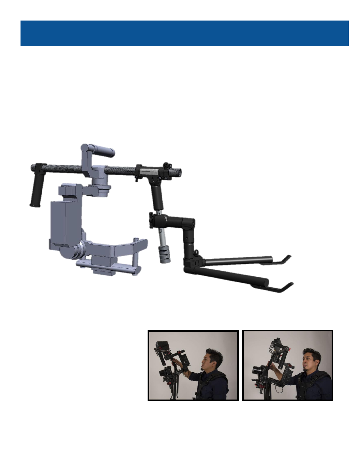
Steadimate Operating
We’re almost there! Let’s learn to pick up the rig and get the arm adjusted for your body
and the weight of the Steadimate System. You’ll have to be wearing the weight of the system
to make these adjustments.
With the tuning stand raised so the
Handlebar of your motorized gimbal is
roughly at your chin level, bow to the
Steadimate and place the Arm Post into the
receiver on the Post Block.
Keep your knees straight and bend at the
hips.
Take a step towards the Steadimate and stand
up straight. Let the arm take the weight and
compress.
You can now lift the Steadimate System clear
of the tuning stand and step back.
Docking again is the exact opposite; rest the
handlebar on the tuning stand and bow to
release the Arm Post before stepping back.
7
Page 33

Lifting the System & Adjusting the Arm
Adjust the Lift:
Important: The Lift adjustment knobs can only be adjusted when the arm segments are
horizontal or slightly above horizontal. Do not force the knobs when the arm is unloaded or
boomed too far up or down. At the correct angle, the knobs turn very easily.
If the arm floats too high or too low for your payload, it will be necessary to lift or lower it to find
that sweet spot to make adjustments.
Ideally, both arm sections will come to rest
slightly above horizontal, by about 5-10˚.
With the arm in the middle of its boom range,
does it rise or fall?
Turn the Forearm Lift Adjustment Knob
clockwise to add lifting strength or
counterclockwise to reduce the lifting strength.
Make small adjustments until the Forearm
segment is lifting the Steadimate System just
above horizontal.
Repeat the adjustment on the Upper Arm
section in the same way. Look to get the
Upper Arm to follow the Forearm section as
you boom up and down.
Caution: Never let your hand or fingers reach
into the open areas of the arm near the
springs. If the arm rises while anything is in
this area, it may be pinched and injured.
7-1
Page 34

Steadimate Operating
Testing your threads:
Stand up straight and look straight ahead.
Is the Steadimate System comfortably staying
in one place in front of you?
Note: it’s helpful to remember your thread
settings so you can return to the ideal settings
quickly next time.
If the rig tends to move straight away from
you; loosen the bottom Thumbscrew and tighten
the top Thumbscrew until the rig is neutral. Then
re-tighten the bottom Thumbscrew.
If the rig tends to move towards you; loosen
the top Thumbscrew until the rig behaves and then
tighten the bottom Thumbscrew.
Remember: both Thumbscrews must be snug
before you get to work.
Typically, your side-to-side adjustment won’t need to be changed, but if the System does move to one side,
you can correct it here.
Remove the arm and add or subtract a half turn of the top Adjustment Wheel at a time and retest.
Most operators leave the bottom Adjustment Wheel at 0 turns and the top Adjustment Wheel set 1.5-2.5
turns out from 0.
7-2
Page 35

Check your Threads
7-2.1
Page 36

Steadimate Operating
The Steadimate System is now capable of helping you create dynamic, endless, moving
shots all day long. It is truly a hybrid machine with its own unique strengths. And yet, you can
still quickly take advantage of handheld opportunities when needed and then go right back to
Steadimate mode with the Arm and Vest without losing a beat. Handoffs are even possible!
The balance of the Steadimate allows very light control input for tilt and panning moves. This
fingertip control allows increased accuracy and repeatability of shots. More importantly, you
can truly ‘fly’ the camera now, letting the inertia of the rig increase the spacial stabilization.
Before we explore Steadimate Operating,
remember that you’re still able to pick up the
motorized gimbal by hand for traditional
operating. No need to replace the original
hand grip or rebalance the Steadimate.
This allows you to decide the best mode for
each and every shot with no setup changes.
When operating as Steadimate, stand up straight whenever possible and let the Arm and Vest do the work.
Your static posture should place most of your weight on one foot so you’re always ready to move in any
direction.
7-3
Page 37

Operating Modes, Tips & Tricks
When walking backwards for a leading shot,
use a spotter to keep you safe.
Your spotter can place a hand on the back of
your vest to guide you clear of obstacles or
even catch you if you misstep.
Learn to look away from the monitor briefly
while walking back; you can maintain framing
even when you’re not looking!
Similar to traditional Steadicam operating, we
start and finish every move with the arm.
At the start of a shot, before taking a step,
move the Steadimate System in the direction
of travel and then follow along on foot.
At the completion of the shot, stop walking
first and bring the camera to rest with only
your arm movement.
And if you don’t have to step, don’t step!
We can extend our range of movement by
sitting down or kneeling.
Or by stepping up onto objects like apple
boxes, curbs or benches.
It’s also possible to kneel on a western dolly to
get very low, but be careful.
7-3.1
Page 38

Steadimate Operating
It is possible to do handoffs with an operating
partner for trick shots like going through
windows or over tables.
Slide your hand down from the Steadimate
Hand Grip onto the top of the arm, press down
and bow slightly.
Your partner is able to lift the Post Block off
the Arm and take over. The reverse also
works; picking up the rig from your handheld
buddy. Practice these tricks off set and get in
sync with your partner.
Be very careful where you place your fingers
so they don’t get pinched when the arm rises.
7-3.2
You may wish to operate with the Steadimate
inverted even with a light system. You may find it
more comfortable for certain shots, or you wish to
raise the lens a little.
To operate in inverted mode:
Reverse the motorized gimbal orientation on the
handlebar so the camera faces forward.
Adjust the Post Block height so the Steadimate tilts
with that familiar fingertip control.
For more information, you can refer to the Inverted
Mode Balance section starting on page 4-4.
Page 39

Operating Modes, Tips & Tricks
7-3.3
If you’re walking through a skinny door, here’s
a trick:
Go one handed while approaching the door and
use the free hand to force the center hinge of
the Arm inward, making you narrow.
Important: DO NOT to place your fingers
inside the arm mechanism or it might bite!
Page 40

Steadimate Accessories
Here are a few Tiffen accessories you might want to add to your Steadimate System. Check
our website at www.Steadicam.com for the latest innovations in camera stabilization.
Arm Post Adapters
Available for ⅝” and ¾” posts
Adapt the Post Block to use your Steadimate
with various brands and models of arms
P/N DESCRIPTION
816-7923-02 ⅝” Arm Post Adapter
816-7923-03 ¾” Arm Post Adapter
Balance Weights
Additional ¼ lb weights
¼-20 threaded for easy counterbalance
adjustments
P/N: 821-7910
8
Balance Spud
Available in 5/8” and ¾”
Adapt the Balance Pin to use your Steadimate
with various brands and models of arms
P/N DESCRIPTION
816-7927-02 ⅝” Balance Spud
816-7927-03 ¾” Balance Spud
Page 41

Maintenance and Cleaning
The Steadimate
A microfiber cloth misted with window cleaner
can be used to remove grime and fingerprints.
Do not use harsh chemicals.
A touch of light grease on threads can help
them work smoother, but DO NOT attempt to
lubricate the bearings in the Post Block.
Check the movement and condition of all parts
between shoots to ensure everything is
operating properly.
The Vest
Use a lightly dampened microfiber cloth to
wipe dirt and grime off the hard parts of the
vest.
Since the vest pads are removable, they can
be hand washed and air-dried. Not a bad idea
after a few shoots in warm weather.
Check the mechanical pieces occasionally for
wear, damage and fasteners that may have
come loose.
The Arm
Like the rest of the system, cleaning the arm
is just a matter of wiping it with a microfiber
cloth sprayed with window cleaner.
Visually check the arm for any damage,
especially if it’s experienced rough use.
DO NOT lubricate any part of the arm! It
should be silent, free moving and consistent.
If for any reason it’s not, contact Tiffen for
service.
9
Page 42

10
Page 43

Contact Tiffen
The Tiffen Company
Address:
90 Oser Avenue
Hauppauge, NY 11788
Phone: (631) 273-2500 1(800) 645-2522
Fax: (631) 273-2557
Tiffen-Steadicam
Address:
2815 Winona Avenue
Burbank, CA 91504
Phone: (818) 843-46001(800) 593-3331
Fax: (818) 843-8321
Tiffen International Ltd.
Address:
Pinewood Studios
Pinewood Road
Iver Heath
SL0 0NH
United Kingdom
Phone: (44) 1753 783 960
E-Mail:
info@tiffen.com
steadicam@tiffen.com
www.tiffen.com/steadicam
Contact Tiffen
10.1
Page 44

 Loading...