

Installation and Maintenance
Guide
Cascade installation
of modulating oil-fired
condensing boilers
Biofell 30 BV
Biofell 50 BV

Page 2 of 20 601130040 [Revision 1502.00] [subject to changes with no previous notice] Biofell Cascade
1 Set Measurements .............................................................................................................................................................. 3
2 Power Connections ............................................................................................................................................................ 3
2.1 Basic Hydraulics ................................................................................................................................................................................ 4
2.2 Filling the System .............................................................................................................................................................................. 5
2.2.1 General Notes ........................................................................................................................................................................... 5
2.2.2 Water Features .......................................................................................................................................................................... 5
3 Combustion Waste Disposal ............................................................................................................................................. 6
3.1 Single Exhaust Pipes......................................................................................................................................................................... 6
3.2 Evacuation Manifold .......................................................................................................................................................................... 7
3.3 Drainage of Condensate.................................................................................................................................................................... 8
4 Fuel Installation .................................................................................................................................................................. 9
5 Temperature Control .......................................................................................................................................................... 9
5.1 Heat Demand ...................................................................................................................................................................................... 9
5.1.1 Heating and DHW Controlled by Biofell’s Cascade System ...................................................................................................... 9
5.1.2 Heating and DHW Controlled by an External Device (0-10 v) ................................................................................................... 9
5.2 Module Ignition Sequence ................................................................................................................................................................ 9
6 Electric Wiring .................................................................................................................................................................... 9
6.1 Wiring diagram ................................................................................................................................................................................. 10
7 Settings ............................................................................................................................................................................. 12
7.1 Configuring All Modules ................................................................................................................................................................. 12
7.2 Configuring Module 1 [master] ....................................................................................................................................................... 14
8 Temperature Display ........................................................................................................................................................ 15
9 System Parameters .......................................................................................................................................................... 15
9.1 Operation Levels .............................................................................................................................................................................. 16
9.2 LPB Parameters ............................................................................................................................................................................... 16
9.3 Configuration Parameters ............................................................................................................................................................... 16
9.4 Boiler Parameters ............................................................................................................................................................................ 16
9.5 DHW Parameters .............................................................................................................................................................................. 16
9.6 CCP/CCB Heating Parameters ........................................................................................................................................................ 16
9.7 Maintenance Parameters................................................................................................................................................................. 17
10 Alarm Codes ..................................................................................................................................................................... 17
11 Settings Tab ...................................................................................................................................................................... 18
12 Monitoring and Maintenance Plan .................................................................................................................................. 18
Thank you for choosing a Tifell boiler. Within the Tifell range of products you have chosen one Biofell model. This is a boiler capable of providing the right comfort level for your
home, together with an adequate, diesel-powered hydraulic system delivering a balanced and economical supply of domestic hot water.
This document is an integral and essential part of the product, and shall therefore be delivered with it to the user. Read the warnings and advice contained in this manual, as
they provide important information about the product’s safe installation, use and maintenance.
The installation of this boiler must be carried out by qualified personnel in accordance with current standards and following the manufacturer's instructions.
Both commissi oning and maintenance of these boilers should be performed by Ti fell’s Official Technical Assi stance Service.
Current Spanish regulations on thermal installations in buildings, Royal Decree 1027/2007 of July 20, hold the owner or user responsible for the installation and maintenance of
machinery and equipment, regardless of whether there exists a legal warranty on them by the manufacturer or seller. They also demand a mandatory annual inspection. Breach
of this requirement may hold the owner or user liable for any damage to third parties, without prejudice to any administrative penalties applicable.
Improper installation of these boilers can cause damage to people, animals and objects. The manufacturer disclaims all responsibility in this regard.
Biofell Cascade 601130040 [Revision 1502.00] [subject to changes with no previous notice] Page 3 of 20
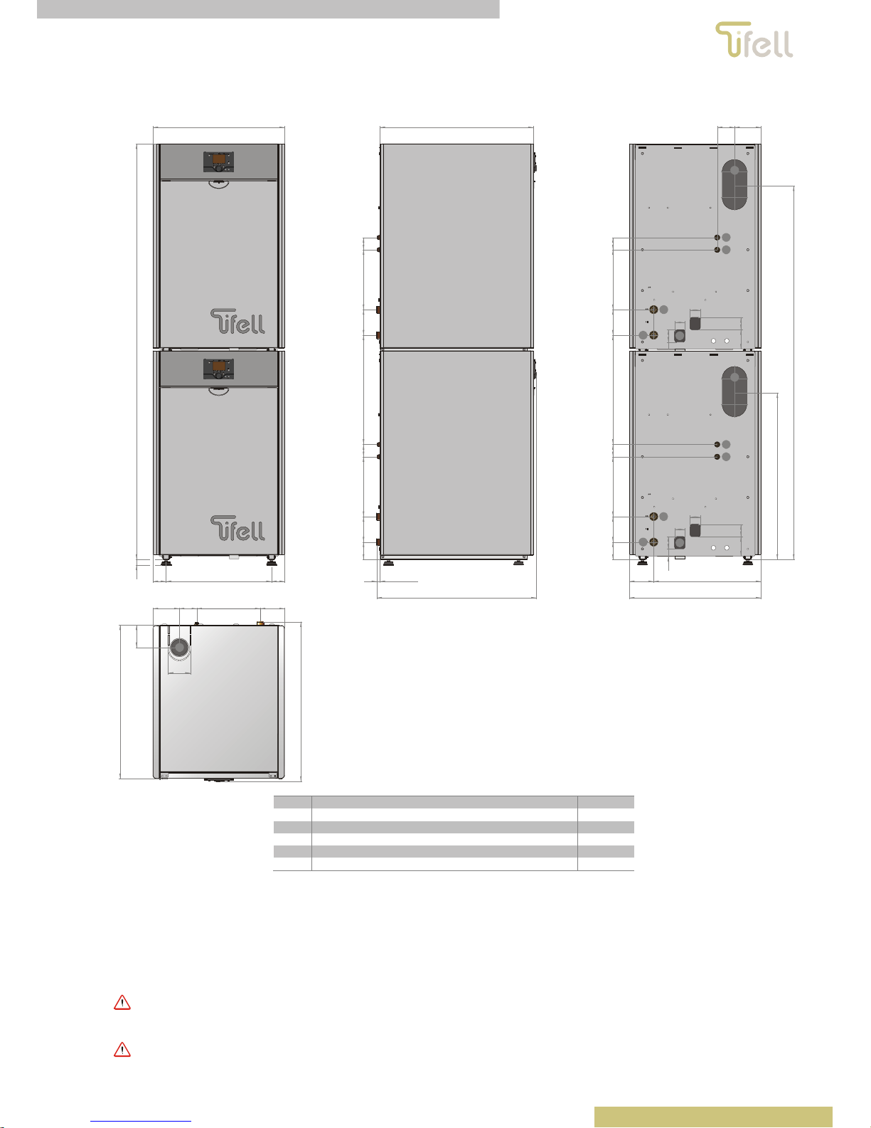
1 Set Measurements
129,50
110
780,2
84,5 310 119
749,5
110
K
2.028,5
643
28
64 515 64
535,5 60 292124,5
749,5
84,5 60 292124,5
15,70
780,2
84,5 129,5
533,5 60 292124,5
95
60
50
50
60
1.823 [Biofell 50] / 1.880 [Biofell 30]
K
84,5 60 292124,5
95
60
50
50
60
643
524119
35
813 [Biofell 50 ] / 870 [Biofell 30]
K
J
D
F
A
B
J
D
F
A
B
A
Fuel inlet 3/8”M
B Fuel return 3/8”M
D Heating return 3/4”M
F Way of heating 3/4”M
J Condensate outlet 20 mm
K Flue 80 mm
Figure 1
2 Power Connections
Up to 16 sets of Biofell BV [30] [50] thermal units (modules) may be installed.
If the heating circuit is old, or likely to contain or generate sludge or impurities that can clog the modules’ heating bodies, a plate heat exchanger must be
installed to separate the heating circuit from the modules.
In case of not using a plate heat exchanger, it is imperative to install a balanced needle, and a sludge filter and/or decanter, on return
modules. This obligation is doubly justified when the gage height at installation exceeds a 2-bar pressure.
Before hydraulically connecting the modules to the insta llation, a sweep of the entire hydraulic circuit should be performed.
Page 4 of 20 601130040 [Revision 1502.00] [subject to changes with no previous notice] Biofell Cascade
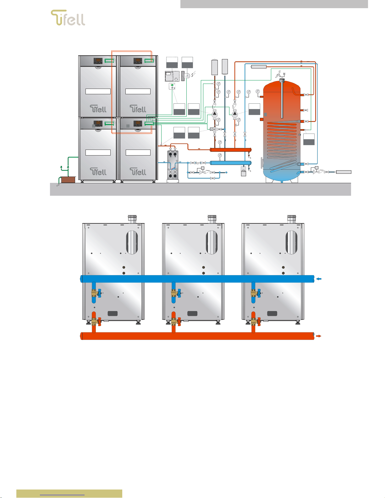
2.1 Basic Hydraulics
15
1616
DHW OUTPUT
GENERATOR CONDENSA TION
FLUE CONDENSATI ON
FILLING
THE
SYSTEM
MIXED CIRC UIT´ S
FLOW
MIXED
CIRCUIT´S
RETURN
COLD WATER INLET
Module 1Module 2
Module nModule 3
S
ACS
M B3
S
CAL
M B 1X
TA
CAL
M H3
0-10v
M H3
S
E
M B9
B
CAL
QX1 N
B
ACS
Q3 N
VM
CAL
Y2 Y1
Figure 2
Figure 3
Biofell Cascade 601130040 [Revision 1502.00] [subject to changes with no previous notice] Page 5 of 20
Figure 4
2.2 Filling the System
2.2.1 General Notes
To prevent lime scale damage to the DHW exchanger, the feed water hardness should not exceed 15°fH. In any case it is advisable to
check the water used, and install the appropriate device for its treatment.
To fill up the system, clean tap water must be used only. If adding antifreeze chemicals, a hydraulic breaker must be installed in the filling
system, to allow separation between the heating circuit and the water circuit.
After making the hydraulic connections, complete the installation as follows:
Check that the pump is not blocked.
Check that the automatic air vent is loose to allow gas evacuation.
Open the DHW’s main circuit input.
Unscrew the pump cap to remove any air bubbles, and close it when water comes out of it.
Open the traps on any devices connected to the circuit, and control the process of removing any air. When water comes out, close radiator straps.
Check the gauge so that installation pressure reaches a value of about 1.5 bar.
If after performing the operations indicated, a decrease in pressure is detected, open the fill again until the gauge pressure reaches 1.5 bar.
Ensure that the fill is securely closed.
2.2.2 Water Features
To ensure that the device should work properly, take into account the following basic rules:
Make sure there are no leaks, and closing any large or evident ones.
If there is an automatic filling system, a counter should be available to determine the size of any leaks.
To fill the system soft water should be used to reduce the total hardness. Furthermore, water must be treated to keep the pH value within corrosion-
preventing limits.
For new installations or boiler replacements, installations must be effectively filtered or screened to protect the boiler from impurities and air.
Ensure that no water come out of the system during maintenance operations, even though the amount seem insignificant: for example, it is
recommended that the system incorporate cutting keys allowing filter cleaning.
Before connecting the boiler, the system’s water should always be tested to check if the values shown advice emptying the system, using existing
waters or performing a chemical cleaning (if the system is particularly dirty or clogged) before filling it with treated water.
Water treatment

Page 6 of 20 601130040 [Revision 1502.00] [subject to changes with no previous notice] Biofell Cascade
To preserve the primary circuit heat exchanger and ensure optimum heat transfer, the features of the water flowing through the boiler’s primary condensate
exchanger must remain constant over time. Preparatory work such as the system’s cleaning and maintenance, checking water features, and installing
filtration systems are essential to achieve this goal.
The choice of water treatment should be made according to the water features, the system type, and the limits of purity required.
Oxygen
Inevitably a certain amount of oxygen will infiltrate the system, both in the filling phase and during operation (system refills, or using materials without
oxygen barrier). Oxygen reacts with steel, causing corrosion and sludge formation. The heat exchanger is made of stainless steel to avoid corrosion, but
sludge may accumulate on hot parts, including the exchanger. As a consequence, the boiler’s power is reduced, and the primary exchanger’s active parts
may obstruct, which in turn may damage the boiler.
To limit this consequence one can resort to:
Mechanical systems: a suitable combination of traps and water softener reduces the amount of oxygen present in the system.
Chemical systems: additives that allow oxygen to remain dissolved in water.
Hardness
Depending on the mains water hardness, its calcium content varies. Calcium sticks to hot parts, including the primary heat exchanger. This may reduce the
boiler’s capacity, and obstruct the primary exchanger’s active parts, which can seriously damage the boiler.
If the mains water does not comply with the values shown in the following table, then it must be treated to soften it. Additives can be used to keep the lime
dissolved. Water hardness should be controlled regularly, and the following values recorded:
A
cidit
y
6,6 < pH < 8,5
Conductivity 400 ÷ 600 μS/cm (a 25°C)
Chlorides < 125 mg/l
Iron < 0,5 mg/l
Coppe
r
< 0,1 mg/l
When the above values are exceeded, applying a chemical treatment is necessary.
Remember that the choice of a water treatment should be made according to the water features, the system type, and the limits of purity
required.
3 Combustion Waste Disposal
3.1 Single Exhaust Pipes
The installation of exhaust ducts for combustion products must be performed by qualified personnel, and must comply with the requirements of the national
and local laws and regulations. The Biofell boilers are pressurized, so the evacuation of combustion products is via a sealed 80 mm-diameter outlet duct,
while the air is taken in from the room where the boiler is installed.
All accessories used in the evacuation of combustion products must be supplied by Tifell.
The maximum flue length (L) that can be installed is:
Flue’s maximal length D=80
Models Maximum length
Biofell 30
15.00 m
Biofell 50
7.00 m
When setting up the flue, one must consider the equivalent lengths of the fittings listed in the following table in any case maximum length be exceeded.
Equivalent lengths of accessories
Accessory
V
ertical Horizontal
1,000 mm linear section 1.00 m 1.50 m
90º bend 1.50 m 2.50 m
45º bend 1.75 m 1.00 m
It is recommended to place the vent pipe slightly inclined (2 to 3 %) upwards, thus preventing its blowing out condensate produced in the duct. Do not turn
the flue more than four times in the whole length of the discharge.
If the flue is completely vertical, and its length grea ter than 3 m, a condensation-collecti ng siphon should be connec ted to a drain on the
duct’s base.

Biofell Cascade 601130040 [Revision 1502.00] [subject to changes with no previous notice] Page 7 of 20
1,00 m
2,50 m
L > 3,00 mminimum 300 mm
1,0
0
m
2,50 m
L < 3,00 m
Figure 5
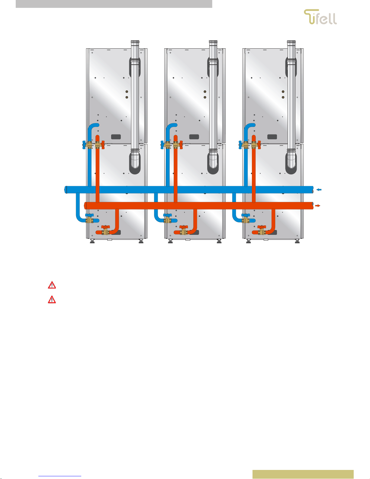
3.2 Evacuation Manifold
For cascade installations with a common exhaust manifold, it is necessary to install smoke check valves in each of the modules that make
up the whole.
All accessories used in the fume exhaust duct shall be suitable for condensing boilers, and resistant to the corrosive action of the acid condensation
generated by the combustion of liquid fuels.
In any case, flue condensate must be prevented from infiltrating the main exchanger.
Prevent the ducts that empty into the manifold from:
facing one another, to avoid smoke from one device revoking another.
Being connected to the manifold’s bottom, so that the flue condensate is collected in the main exchanger.
Figure 6 Figure 7

Page 8 of 20 601130040 [Revision 1502.00] [subject to changes with no previous notice] Biofell Cascade
182 mm 182 mm
M
i
n
i
m
u
m
s
l
o
p
e
:
3
%
Figure 8
M
i
n
i
m
u
m
s
l
o
p
e
:
3
%
M
i
n
i
m
u
m
s
l
o
p
e
:
3
%
Figure 9
3.3 Drainage of Condensate
The condensation generated by the combustion of liquid fuels can have a pH below 5, so to neutralize the acidity neutralizationgranulate must be installed in
the drain (Figure 10).
The pH of condensate outlet to the drainage network must be controlled periodically so that its value does not drop below 7.

Biofell Cascade 601130040 [Revision 1502.00] [subject to changes with no previous notice] Page 9 of 20
1 2
3
4
6
5
978
1 Drain
2 Condensate collection
3 Water
4 Neutralization granulate
5 Filter
6 Grating
7 Siphon
8 Charcoal bag
9 Condensate
Figure 10
4 Fuel Installation
Biofell boilers incorporate a modulating oil burner. For proper fuel installation, proceed according to each boiler’s instructions. Fuel installation and burner
start-up must be carried out by qualified, authorised personnel.
In order to ensure a correct fuel supply, a deaerator filter should be installed in the burner’s fuel vacuum cleaner for each of the modules.
5 Temperature Control
The accumulate temperature is controlled through a DHW sensor connected to the M B3 input; and heating or primary temperature is controlled through a
probe placed in the balanced needle or exchanger plates primary connected to the input M BX1.
5.1 Heat Demand
5.1.1 Heating and DHW Controlled by Biofell’s Cascade System
Heating demand is managed via a voltage-free contact connected to M H3. The drive temperature can be adjusted manually at fixed temperature, or it can
be made to depend on the outside temperature by means of an external probe connected to M B9. To that effect the external probe mode must be enabled
on module 1 [parameter 1326], and the heating curve should be adjusted [parameter 1320].
The DHW storage tank temperature and the heat demand are managed through DHW probe connected between M B3. The DHW temperature is set with
parameter 1610.
5.1.2 Heating and DHW Controlled by an External Device (0-10 v)
The heat demand in the Biofell cascade system can be controlled and/or effected by a 0-10 VDC voltage obtained from an external upper control.
This properly polarized signal is connected to the module 1 through connection M H3, which must be configured as a "heat request" in the 5960 parameter.
The Biofell cascade system stops operation if the signal’s voltage falls below 1 V DC signal; or varies the setpoint temperature according to a curve
defined by the parameter 5964 (temperature set to 10 V).
5.2 Module Ignition Sequence
The ignition module will rotate depending on the number of operation hours set by the parameter 3540.
6 Electric Wiring
For communication, modules should be connected in parallel and comply with the polarity of the MD BD connection on all modules.

Page 10 of 20 601130040 [Revision 1502.00] [subject to changes with no previous notice] Biofell Cascade
nnn np nnpnkh f bbb
a
M UX M BX4 M BX3 M MH3 B12 M BX2 M MBX1 B1 M MH1 M B3B9 M B2 G+ CL- CL- CL+CL- CL+ MB DB
X50
X60
X30
BSB
LPB
ZUU TS U TSRQ NLP
CL+
QX4QX4
FX4EX2
QX3NQX2NY6 Y5 Q6
NY2
QX1
NN NY1Q2N
Q3 SK1SK24S3
T2NT1NL1S3L1 N L
nnn np nnpnkh f bbb
a
M UX M BX4 M BX3 M MH3 B1 2 M BX2 M MBX1 B1 M MH1 M B3B9 M B2 G+ CL- CL- CL+ CL- CL + MB D B
X50
X60
X30
BSB
LPB
ZUU TS U TSRQ NLP
CL+
QX4QX4
FX4EX2
QX3NQX2NY6 Y5 Q6
NY2
QX1
NN NY1Q2N
Q3 SK1SK24S3
T2NT1NL1S3L1 N L
nnn np nnpnkh f
bbb
a
M UX M BX4 M BX3 M MH3 B1 2 M BX2 M MBX1 B1 M MH1 M B3B9 M B2 G+ CL- CL- CL+ CL- CL + MB D B
X50
X60
X30
BSB
LPB
ZUU TS U TSRQ NLP
CL+
QX4QX4
FX4
EX2 QX3NQX2NY6 Y5 Q6
N
Y2QX1
NN N
Y1 Q2NQ3 SK1SK24S3 T2NT1NL1 S3 L1
NL
Module 2 Module 3
Module n
nnn np nnpnkh f
bbb
a
M UX M BX4 M BX3 M MH3 B12 M BX2 M MBX1 B1 M MH1 M B3B9 M B2 G+ CL- CL- CL+CL- CL+ MB D B
X50
X60
X30
BSB
LPB
ZUU TS U TSRQ NLP
CL+
QX4QX4
FX4
EX2 QX3NQX2NY6 Y5 Q6
N
Y2QX1
NN N
Y1 Q 2NQ3 SK1SK24S3 T2NT1NL1 S3 L1
NL
Verde -Am ari llo
Azul
Marrón
Verde -Am ari llo
Marrón
Module 1
Abrir
Cerrar
S
ACS
M B3
S
CAL
M B 1X
TA
CAL
M H3
S
E
M B9
B
CAL
QX1 N
B
ACS
Q3 N
VM
CAL
Y2 Y1
Figure 11
Module 1 will be the main or master, and is where all electrical connections and system configurations are made according to the following table and Figure
11.
Cascade system comp o nent conne ct io n
Component Ref. RVS connector
Heating pump installation B
CAL
QX1 N
A
ccumulation pump B
ACS
Q3 N
DHW sensor/thermostat S
ACS
M B3
Primary flow sensor S
CAL
M BX1
Room thermostat
0-10 V heat demand
TA
CAL
0-10v
M H3 *
Mixing valve VM
CAL
Y2 Y1
* M H3connections in other modules should be open, without bridge
To complete module connection, one must purchase the necessary connectors according to the following tables:
Cascade connection kit, MASTER [BIOFE LL]
Connector Ref. No. Description Items
MB DB 601111490
3-POLE RVS a CONNECTOR
Cascade communication 1
M BX1 CKTETR20
2000 EUROFELL BATTERY PROBE
Collector probe 1
M BX1 601116520
2-POLE RVS n CONNECTOR
Collector probe connector 1
QX1 601116070
3-POLE RVS U CONNECTOR
General pump connector 1
Cascade connection kit, SLAVE [BIOF EL L]
Connector Ref. No. Description Items
MB DB 601111490
3-POLE RVS a CONNECTOR
Cascade communication 1
6.1 Wiring diagram
The module cable connection for cascade operation varies from the standard connection. Unless modules have not been specifically ordered for cascade
operation, make sure the wiring is in accordance with the following scheme.
.

Biofell Cascade 601130040 [Revision 1502.00] [subject to changes with no previous notice] Page 11 of 20
nnn np n npnkh f bbb
a
MUXMBX4MBX3 M MH3 B12 M B X2 M MBX1 B1 M MH1 M B3B9 M B2 G+ CL- CL- CL+ C L- CL+ MB DB
X50
X60
X30
BSB
LPB
Z
UU
T
SU
T
S
RQ NLP
CL+
QX4 QX4
FX4
EX2 QX3
N
QX2
N
Y6 Y5
Q6
N
Y2QX1
NN N
Y1 Q2
N
Q3
SK1SK2
4
S3
T2
N
T1
N
L1
S3
L1
NL
1
1
1
1
J4 J6 J7J5
J8
K1
C18
R22
L16
L18
L4
L5
L2
L3
L17
L15
J13 J14
11
D4
R27
D9
R28
R29
C7
D8
R26
C34
C5
C6
C35
C4C33
L20
D3
R18
R20
R19
C36
R21
R58
R13
R15
R59
R38
R40
R41
R43
D14
R42
R44
R45
D17
D18
R5
D16
R39
U15
U16
1
C9
R2
Q4
Q3
D11
R1
D13
D15
C21
U8
C19
C22
Q5Q6
C12
C11
C20
D12
R51
U1
J9
1
L12
L10
J2 J3
11
C2
C13
D5
L1
D7
R54
R24
C3
C14
R25
R17
L14
R32
D6
C1
R23
C8
L9
L11
R31
R61
R56
R60
U17
R4
1
R30
R8
C10
C16
R3
R9
D1
R33
C17
X1
U12
R47
R37
S1
R46
R64
R16
R14
R57
Q1
C30
D2
TP1
R10
R12
D23
Q8
R11
Q2
R36
U6
1
R6
Q7
R7
U7
R34
TP2
J10
C15
C32
R35
U14
J1
1
R53
L7
L8
R52
D21
L19
R48
L21
C29
R49
R50
C28
C26
R62
C23
D20
U13
C25C2 4
D22
D19
C31 C27
R55
T1
R63
U9
D24
1 12234567891011
N 31 32
F
N
CC
Q
B
CCP
P
CAL
R
S
CAL
FA
P
Q
TE
Q
F
Q
V
Q
M
Q
B
Q
UC
C
CR
C
CM
Q
CRE
Negro
Marrón
Rojo
Gris
Marrón
Azul
Marrón
Azul
Amarillo
Negro
Verde
Negro
Rojo
Gris
Negro
Verde
Verde
Azul
Marrón
Azul
Marrón
Azul
Negro
Negro
Marrón
Negro
Negro
Azul
Marrón
Rojo
Verde
Verde
Azul
Gris
Marrón
Negro
Verde
Verde
Marrón
Azul
Azul
Marrón
Rojo
Gris
Negro
Azul
Rojo
Negro
Azul
Marrón
Azul
Marrón
Verde
Rojo
Verde- Amari llo
Azul
Marrón
Verde
Negro
Marrón
Marrón
Azul
A
z
u
l
Negro
Rojo
Gris
Gris
Azul
Azul
Verde
Verde
TS
CAL
Power supply + 15
TACO (Hall sensor OUT)NCPWM input
Power supply - (GND)
Marrón
Ro
j
o
Negro
Azul
V
Q
figura 12
Element BV / S
B
CCP
Heat pump (main circuit)
BQ Fuel pump
CC
Q
LMO switchboard
CER Electrical network connection
CM
Q
Burner modulation circuit
CRC RVS regulating switchboard
F
A
Transient filter

Page 12 of 20 601130040 [Revision 1502.00] [subject to changes with no previous notice] Biofell Cascade
Element BV / S
FQ Photocell
MQ Motor
P
CAL
Heating pressure
PQ Fuel preheater
R Resistance
SA
CCP
Room sensor (main circuit)
S
CAL
Boiler probe
SE External probe (optional)
TA
CCP
Room thermostat (optional)
TEQ Power transformer
TS
CAL
Bolier’s safety thermostat
UCC
A
VS control unit
VQ Fan
7 Settings
Before setting the boilers, all slave modules must be switched to stand-by position by pressing the heating mode selection button on each of them until the
signal is under the symbol.
7.1 Configuring All Modules
The module addresses should be set by accessing parameter 6600 as follows:
Operation Display Description
Boiler temp
Default display. If not shown, press the ESC button to return to it.
Press OK.
Time of day and date
Operator section
Hold the INFO button for 5 seconds.
Enduser
Commissioning
Commissioning
OEM
Engineer
Turn the setting knob to access the “Engineer” menu.
Press OK.
Time of day and date
Operator section

Biofell Cascade 601130040 [Revision 1502.00] [subject to changes with no previous notice] Page 13 of 20
Operation Display Description
Configuration
Fault
LPB system
Turn the setting knob to access the “LPB system” menu.
Press OK.
LPB system
Device address
Press OK to enable value modification.
Turn the setting knob to modify the set value.
Press OK to confirm the new value.
Press ESC to return to the default display.
Each module’s address correspond to the number selected in this parameter:
Parameter
value
Module
Parameter
value
Module
Parameter
value
Module
Parameter
value
Module
1 Module 1 5 Module 5 9 Module 9 13 Module 13
2 Module 2 6 Module 6 10 Module 10 15 Module 14
3 Module 3 7 Module 7 11 Module 11 15 Module 15
4 Module 4
8 Module 8 12 Module 12
16 Module 16
Repeat this procedure for all modules, sketching their place in the cascade.
The segment address in the 6601 parameter should be set to 0 for all modules. To this effect:
Operation Display Description
Boiler temp
Default display. If not shown, press the ESC button to return to it.
Press OK.
Time of day and date
Operator section
Hold the INFO button for 5 seconds.
Enduser
Commissioning
Commissioning
OEM
Engineer
Turn the setting knob to access the “Engineer” menu.
Press OK.

Page 14 of 20 601130040 [Revision 1502.00] [subject to changes with no previous notice] Biofell Cascade
Operation Display Description
Time of day and date
Operator section
Configuration
Fault
LPB system
Turn the setting knob to access the “LPB system” menu.
Press OK.
LPB system
Device address
LPB system
Segment ad dress
Turn the setting knob to reach segment-address parameter 6601.
Press OK to enable value modification.
Turn the setting knob to modify the set value.
Press OK to confirm the new value.
Press ESC to return to the default display.
After these operations remove and restore power on all modules.
7.2 Configuring Module 1 [master]
In Module 1 [master] one must configure a number of parameters accessed through the "Settings" menu. To do this, proceed as follows:
Operation Display Description
Boiler temp
Default display. If not shown, press the ESC button to return to it.
Press OK.
Time of day and date
Operator section
Hold the INFO button for 5 seconds.
Enduser
Commissioning

Biofell Cascade 601130040 [Revision 1502.00] [subject to changes with no previous notice] Page 15 of 20
Operation Display Description
Commissioning
OEM
Engineer
Turn the setting knob to access the “Engineer” menu.
Press OK.
Time of day and date
Operator section
DHW storage tank
LPB system
Configuration
Turn the setting knob to access the “Configuration” menu.
Press OK.
At this point we can access the configuration parameters by turning the setting knob. The parameters to be configured in module 1 are:
Parameter 5730: DHW probe or thermostat (thermostat incompatible with the Anti-Legionella feature)
Parameter 5731: Q3 DHW actuator - Charge pump/diverter valve
Parameter 5930: BX1 probe input - B10 common drive probe
Furthermore, if the cascade system comprises Biofell SUN, it must be set as follows:
Parameter 5932: BX3 probe input - B10 common drive probe
8 Temperature Display
The flow sensor/collector temperature is displayed in the control panel of the boiler set as module 1. The temperature displayed in other modules viewports
will be specific to each module.
9 System Parameters
To configure the system, one must access the "Engineering (F)" level, and proceed as follows:
Operation Exam pl e di spl ay Description
Boiler temp
Default display. If not shown, press the ESC button to return to it.
Press OK.
Time of day and date
Operator section
Hold the INFO button for 5 seconds.
Enduser
Commissioning
Turn the setting knob to access the “Engineer” menu.

Page 16 of 20 601130040 [Revision 1502.00] [subject to changes with no previous notice] Biofell Cascade
Operation Exam pl e di spl ay Description
Press OK.
Time of day and date
Operator section
Configuration
Fault
LPB system
Turn the setting knob to access the “LPB system” menu.
Press OK.
At this point we can access the system parameters by turning the setting knob.
9.1 Operation Levels
User: E
Start-up: I
Engineering: F
OEM: Not accessible without a code
9.2 LPB Parameters
Operation line
Operation
level
Feature Value to adjust Min Max Unit
6600 F Device address 1 1 16 1
6601 F Segment address
A
lways 0 0 0 0
9.3 Configuration Parameters
Operation line
Operation
level
Feature Value to adjust Min Max Unit
5730 F DHW B3 probe Probe Thermostat Probe 5731 F DHW B3 actuator Pump Pump V3
V
-
5930 F BX1 probe input B10 common drive probe - - -
5932 (Biofell Sun only) F BX3 probe input B10 common drive probe - - -
5960 F H3 feature input 0-10V heat demand
5964 F H3 10V temperature 50/80 8 85 ºC
9.4 Boiler Parameters
Operation line
Operation
level
Feature Default value Min Max Unit
2210 F Primary’s min. temperature 8 8 Manual set ºC
2212 F Primary’s max. temperature 80 Manual set 85 ºC
9.5 DHW Parameters
Operation line
Operation
level
Feature Value to adjust Min Max Unit
1610 E-F DHW B3 probe Probe Thermostat Probe -
1640 F
A
nti-Legionella feature
Off, Periodically, Fixed day
Periodically - - -
1641 F
A
nti-Legionella feature period 7 1 7 Days
1642 F
A
nti-Legionella feature fixed-day activation Saturday Monday Sunda
y
-
1644 F
A
nti-Legionella feature activation time 03:00 00:00 23:50 hh:mm
1645 F
A
nti-Legionella feature max. temperature setting 70 55 95 ºC
1646 F
A
nti-Legionella feature max. activation interval 30 10 360 min
5020 F
Primary’s temperature increase on DHW
temperature set
12 (SUN/M models)
20 (T/BV/AS models)
0 30 ºC
9.6 CCP/CCB Heating Parameters
Operation line
Operation
level
Feature Default value Min Max Unit

Biofell Cascade 601130040 [Revision 1502.00] [subject to changes with no previous notice] Page 17 of 20
1320 E-F Heating curve slope 1.5 0.10 4.00 0.10
1321 F Heating curve shift 0.0 -4.5 +4.5 ºC
1326 F Heating curve adaptation Of
fOff
On
1330 F Winter/summer heating limit 18 ---/8 30 ºC
1340 F Min. drive limit 8 8 P 1.314 ºC
1341 F Max. drive limit 80 P 1.340 80 ºC
9.7 Maintenance Parameters
Operation line
Operation
level
Feature Default value Min Max Unit
7044 F Range of months for maintenance 12 --- 12 Months
7170 F SAT phone 0000xxxxxxxxx - - Tel.
10 Alarm Codes
Biofell boilers are equipped with an electronic circuit capable of detecting any malfunction through a continuous self-test. When the control panel detects a
malfunction, it signals it with the icon
. If this happens, press the "Info" button to find out what triggered the alarm. The following list breaks down the main
alarm codes and their meanings:
Code Description Effect
0 No error
10 Error in external probe Disables affected part
20 Error in boiler 1’s temperature probe 1 (one-way probe) / Water pressure switch failure Stops the entire system
30 Error in flow temperature probe 1 (CC1 probe) Disables affected part
50 Error in DHW temperature sensor 1 (DHW thermostat/ probe) Stops the entire system
60 Error in room temperature sensor 1 (CC1) Disables affected part
68 Error in room temperature sensor 3 (CCP) Disables affected part
81 LPB short circuit (RVS63 switchboard) Disables affected part
83 BSB cable short circuit (room temperature sensor) Disables affected part
84 BSB address collision (room temperature sensor) Ignores affected part
85 BSB radio communications failure (room temperature sensor) Disables affected part
105 Maintenance message View maintenance code table
126 DHW load monitoring Disables affected part
131 Burner failure. Error in safety thermostat Stops the entire system
146 Common configuration error message Ignores affected part
217 Common sensor error message Disables affected part
326 BX/mixing valve group, same sensors Ignores affected part

Page 18 of 20 601130040 [Revision 1502.00] [subject to changes with no previous notice] Biofell Cascade
11 Settings Tab
In order to facilitate subsequent interventions, the values set at commissioning should be recorded on the following table:
Manufacturing No. Module No. Manufactur ing No. Module No.
1
9
2
10
3
11
4
12
5
13
6
14
7
15
8
16
Configuration
Operation line
Operation
level
Feature Value to set Adjusted value
5730 F DHW B3 probe Probe
5731 F DHW B3 actuator Pump
5930 F BX1 probe input B10 common drive probe
5932 (Biofell
SUN only)
F BX3 probe input B10 common drive probe
5960 F H3 feature input 0-10V heat demand
5964 F H3 10V temperature 50/80
Boiler
Operation line
Operation
level
Feature Default value Adjusted value
2212 F Max. primary’s temperature 40/80
Domestic hot water
Operation line
Operation
level
Feature Value to set
1610 E-F DHW B3 probe Probe/Thermostat
1640 F
A
nti-Legionella feature
Off, Periodically, Fixed day
Off/Periodically/Fixed day
1641 F Anti-Legionella feature period 7
1642 F Anti-Legionella feature fixed-day activation Saturday
1644 F Anti-Legionella feature activation time 03:00
1645 F Anti-Legionella feature max. temperature setting 70
1646 F Anti-Legionella feature max. activation interval 30
5020 F
Primary’s temperature increase on DHW
temperature set
20
CCP/CCB heating
Operation line
Operation
level
Feature Default value
1320 E-F Heating curve slope 1.5
1321 F Heating curve shift -4,5ºC ÷ +4,5ºC
1326 F Heating curve adaptation Off/On
1330 F Winter/summer heating limit 8ºC ÷ 30ºC
1340 F Min. drive limit 8
1341 F Max. drive limit 80
Maintenance
Operation line
Operation
level
Feature Default value
7044 F
Range of months for maintenance
12
12 Monitoring and Maintenance Plan
Preventive maintenance requires performing the tasks listed below for their record keeping. Omission thereof may void the warranty.

Biofell Cascade 601130040 [Revision 1502.00] [subject to changes with no previous notice] Page 19 of 20
Maintenance tab
Model: Biofell [cascade]
Monthly checks
Proper DHW temperature control
Cleaning the condensate collection siphon and its connection to the vault
Checking the tightness of the burner holder cap
Combustion analysis
Smoke temperature [ºC]
Min. power
______________
Max. power
______________
CO2 [%]
______________ ______________
CO [ppm]
______________ ______________
Air excess []
______________ ______________
Performance [%]
______________ ______________
Operation of security systems
Operation of the anti-smoke check valve [cascade systems]
Measuring the condensate’s pH at the neutralizer’s outlet
Measured
value:
____________ pH
Cleaning the heating circuit return filter [if applicable] and dirt separator [if applicable]
Exercising the water pressure switch
Operation of the DHW pump [if controlled by RVS63]
Operation of the heat pump [if controlled by RVS63]
Proper heating temperature control
Correct temperature control on the primary circuit
Measurement of the temperature difference between heating flow and return
Measured
value:
____________ ºC
Inspect and adjust the fuel pump pressure at maximum power [parameter 7710 = 10] Adjusted value: ____________ bar
Inspect and adjust the fuel pump pressure at minimum power [parameter 7710 = 0] Adjusted value: ____________ bar
Check air loadin primary circuit’s expansion vessel Adjusted value: ____________ bar
Check primary circuit’s water acidity [pHmust be between 6.5 and 8.5]
Measured
value:
____________ pH
Check primary circuit’s water hardness [max: 15°fH]
Measured
value:
____________ ºF
Reading the fill meter [max: 20 l / kW]
Measured
value:
____________ l
Yearly checks
Inspect and clean the combustion chamber
Checking the correct state of the air suction and smoke evacuation ducts
Cleaning the outer fuel filter
Cleaning the infrared cell glass
Cleaning the infrared cell
Inspect fuel injector, and replace if necessary
Inspect and clean ignition electrodes
Adjust the distance between ignition electrodes
Cleaning the fuel pump filter
Checking for leaks in the boiler’s hydraulic circuit

601130040 [Revision 1502.00] [subject to changes with no previous notice] Biofell Cascade
Tifell electro solar s.a.
Vitoriabidea, 10
E-01010 VITORIA
Tfno.: (+34) 945 249 300
Fax: (+34) 945 246 181
www.tifell.com
 Loading...