

Page 1
Professional 4-channel
Thermocouple Thermometer
plus Infrared Thermometer
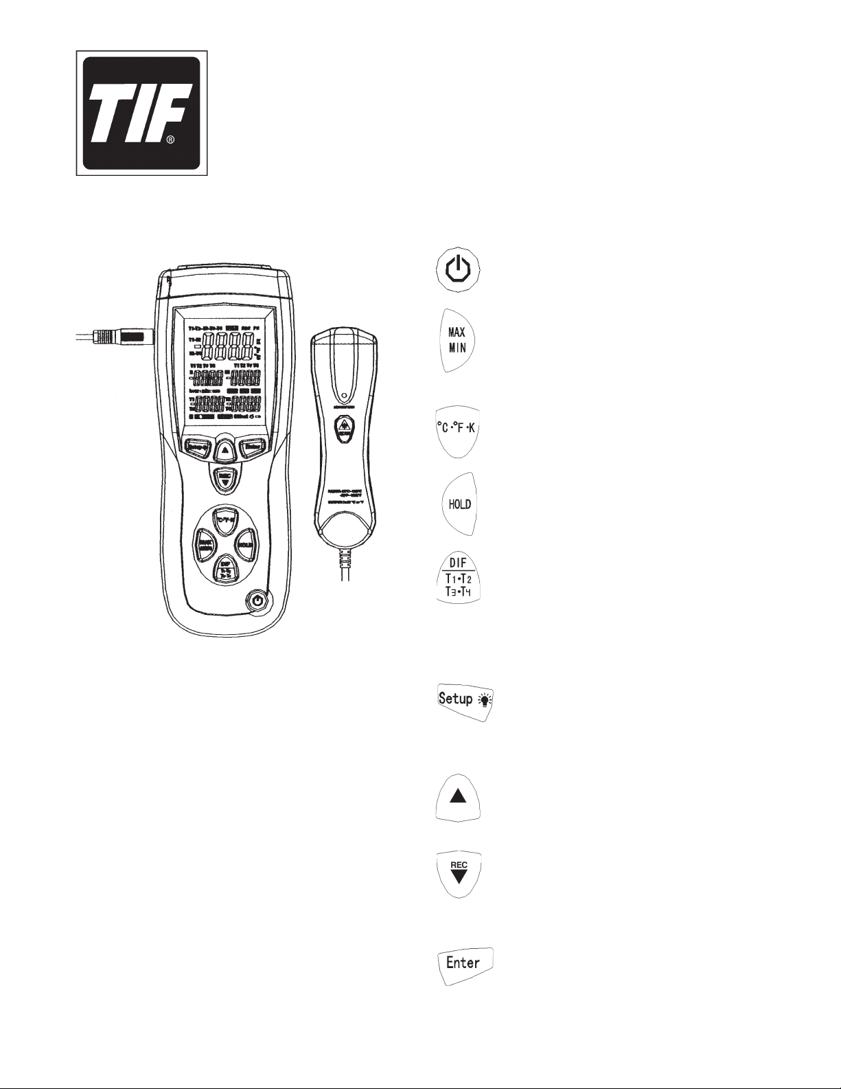
BUTTONS
= Power ON or OFF.
= Steps through maximum (MAX), minimum
(MIN), and average (AVG) readings. To exit
MAX / MIN / AVG mode, press this button for
three (3) seconds.
= Switch between Celsius (°C), Fahrenheit
(°F), and Kelvin (K) temperature units.
TIF3340
INFRARED
THERMOMETER
FEATURES
•
Large backlit display shows any combination of
T1, T2, IR, T3, T4, T1-T2, T1-IR, T2-IR,
IR-T3, and IR-T4,
plus MAX, MIN, and AVG.
T3-T4,
• Relative time clock on MAX, MIN, and AVG
provides a time reference for major events.
• Electronic offset function allows compensation
for thermocouple errors.
• Readout in °F, °C, or Kelvin (K).
• Auto shutdown.
= Freeze and unfreeze display readings.
= Displays T1, T2, IR, T1-T2, T1-IR, and
T2-IR (differential temperature measure ment) in the primary, secondary, and tertiary
displays. Press button for two seconds to
show T3, T4, IR, T3-T4, IR-T3, and IR-T4.
Press button for two more seconds to exit.
= Press once to turn on backlight;
press again to turn off backlight.
Hold for three (3) seconds to access or
exit Setup menu.
= Scrolls to the setup option you want to
change; press again to increase the
displayed setting.
= Press once to record; press again to stop
recording. In Setup menu, scroll to the setup
option you want to change; press again to
decrease the displayed setting.
= Press once to enter a setup option;
press again to store the displayed setting
in memory.
Sheet 1
Page 2
OPERATING INSTRUCTIONS
Displaying Temperatures
1. Plug a thermocouple(s) into the T1, T2, T3, or T4 input connector located at the top of the thermometer.
2. Turn the thermometer ON by pressing .
3. Press to select the preferred temperature scale (Celsius, Fahrenheit, or Kelvin).
4. Hold or attach the thermocouple(s) to the location requiring a temperature measurement. The
temperature reading appears in the primary display.
5. Press to toggle the T1, T2, T3, T1-T2,T1-T3, and T2-T3 readings to show in the primary or
secondary displays.
Notes:
• “ - - - -” is displayed when a thermocouple is defective or not connected.
• OL(overload)isdisplayedwhenthetemperaturebeingmeasuredisoutsidethethermometer’srange.
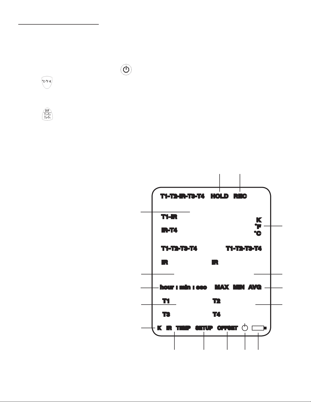
Display Elements
1. Primary display: T1, T2, IR, T3, T4,
T1-T2, T1-IR, T2-IR, T3-T4, IR-T3, or
IR-T4 reading.
2. Tertiary display: The elapsed time or IR
temperature reading.
3. MIN:SEC or HOUR:MIN display.
4. Fourth display: T1 or T3 reading.
5. Thermocouple type.
6. IR temperature.
7. Displays while Setup menu is activated.
8. Setup menu; offset of T1, T2, IR, T3, T4.
9. Auto power OFF.
10. Low power.
11. Fifth display: T2 or T4 reading.
12. MAX, MIN, AVG display.
13. Secondary display: T1, T2, T3, or T4
reading.
14 Unit of temperature.
15. Displays while recording data.
1516
T1-T2-IR-T3-T4 HOLD REC
1
T1-IR
IR-T4
-888.8
T1-T2-T3-T4 T1-T2-T3-T4
IR IR
2
K
•
F
•
C
14
13
-8888 -8888
3
4
5
hour : min : sec MAX MIN AVG
T1 T2
-8888 -8888
T3 T4
K IR TEMP SETUP OFFSET
12
11
16. Displays while freezing data.
Back, Sheet 1
6 7 8 9 10
Page 3

OPERATING INSTRUCTIONS contd.
Holding Displayed Readings
1. Press to freeze the displayed readings.
The display shows HOLD.
2. Press to toggle the T1, T2, IR, T1-T2,
T1-IR, and T2-IR readings in the primary,
secondary, or tertiary display.
3. Press for two seconds to toggle the T3,
T4, IR, T3-T4, IR-T3, and IR-T4 readings in the
primary, secondary, or tertiary display.
4. Press for two seconds again to return to
the original display.
5. Press HOLD to turn off the HOLD option.
Viewing MIN, MAX, and AVG Readings
Using the Infrared (IR) Thermometer
CAUTION: To prevent personal injury, do not stare
into the laser beam. This is a Class 2 laser product.
1. Plug the output of the IR thermometer into the
IR input on the side of the TIF3340. IR TEMP
appears on the display.
2. Aim the IR light at the location to measure.
3. Press . The temperature appears in the
tertiary display.
Shutting OFF the TIF3340
1. Press and hold the button while the
secondary display counts down from three
to zero. The thermometer shuts off after the
display reaches zero.
1. Press to step through maximum (MAX),
minimum (MIN), or average (AVG) readings.
The display shows elapsed time since entering
MAX / MIN / AVG mode, or the time at which
the minimum or maximum occurred.
2. Press for three (3) seconds to exit.
Recording Data
1. When the meter is turned
ON, the number of events
that may be recorded is
shown on the secondary
display.
Note: If the maximum number of events have
been recorded, the meter displays FULL. Refer to
the Setup Menu: Erase the Memory procedure to
clear the events.
1 0000
NOTE: If the sleep timer (SLP) is enabled, the
thermometer automatically shuts down after
twenty (20) minutes of inactivity.
2. Press to record an event. Press the
button again to stop recording.
Sheet 2
Page 4

SETUP MENU
CHANGING SETUP OPTIONS
1. Press for three (3) seconds to enter
Setup Menu. SETUP appears at the bottom of
the display.
2. Press or to scroll to the desired setup
option.
3. Press ENTER to change this setting.
4. Press or
5. Press ENTER to store new setting in memory.
6. Press SETUP for three (3) seconds to exit
Setup Menu.
NOTE: Setup is disabled in MAX MIN AVG mode.
Option Menu Item Settings
Offset T1, T2, IR, T3, T4 T1, T2, IR, T3, or T4 offset
Sample Rate rAt Recording sample rate
Time Setting tiE Show / set the time
Clear CLR Clear memory of events
Sleep Mode SLP ON or OFF
until desired setting displays.
Set the Sample Rate of
Temperature Data Recording
000 1
The default sample rate is one
second, which is displayed on
the secondary display as 0001
(minute–second).
1. While in Setup Menu, press to select
which reading (minute—second) to adjust.
2. Press or
3. Press ENTER to store the new setting in
memory.
until desired setting displays.
Set the Time
The secondary display shows
year, month, and day. The
tertiary display shows hour and
minute. June 10, 2009, 1:31 PM
is displayed in the graphic.
1. While in Setup Menu, press to select
which reading to adjust: year—month—day—
hour—minute.
K SETUP
2009 06 10
1331
K SETUP
Using Offset to Adjust for Probe Errors
The offset option can adjust thermometer
readings to compensate for the errors of a
specic thermocouple and IR temperature. The
adjustment range allowed is: ± 9.0°F or ± 5.0°C.
1. While in Setup Menu, plug the thermocouple
into the input connector.
2. Place the thermocouple in a known, stable
temperature environment (such as an ice dry
well calibrator). Allow the readings to stabilize.
4. Press or until the primary reading
matches the calibration temperature.
3. Press ENTER to store new setting in memory.
Note: The primary display shows the temperature
plus the offset, and the secondary display shows
the offset. Individual offsets can be stored for T1,
T2, IR, T3, or T4.
2. Press or
3. Press ENTER to store the new setting in
memory.
until desired setting displays.
Erase the Memory
The number of events stored is
shown on the secondary display.
This procedure outlines how to
clear the memory.
1. While in Setup Menu, press or until
CLR is displayed.
2. Press ENTER.
3. Press or until YES is displayed.
4. Press ENTER to clear the memory.
K SETUP
8888
Back, Sheet 2
Page 5

SETUP MENU contd.
MAINTENANCE
SLEEP MODE
When in sleep mode, the meter
automatically shuts down after
20 minutes if no buttons have
been pressed during that time.
is displayed if sleep mode
is enabled.
1. While in Setup Menu, press or until
SLP is displayed.
2. Press ENTER until ON or OFF is displayed.
3. Press or until desired setting is
displayed.
4. Press ENTER to store the setting in memory.
Note: If sleep mode is not enabled, the meter
does not automatically shut OFF, and
will not show on the display.
K SETUP
REPLACING THE BATTERY
The thermometer must be OFF when changing
the battery.
1. Press to power OFF the thermometer.
2. On the back side of the thermometer, locate
the symbol.
3. While holding the thermometer, place your
thumb on the . Using gentle pressure,
push downward and pull backward; the battery
cover will begin to open. Use your other hand
to grasp the cover and pull downward. Lift the
cover up and off.
4. Lift out the 9-volt battery and disconnect it from
the harness.
5. Connect the new 9-volt battery to the harness,
and place it into the battery cavity.
6. Install the battery cover by placing it over the
battery and pushing upward until it snaps into
place.
SPECIFICATIONS
General
Battery 9V
Operating Temperature 32°F to 122°F
(0°C to 50°C)
Noncondensing
Storage Temperature 14°F to 122°F
-10°C to 50°C
Temperature Range
K-type Thermocouples -328°F to 2501°F
-200°C to 1372°C
IR Temperature -22°F to 1022°F
-30°C to 550°C
Display Resolution
0.1(°C•°F•K)<1000
1(°C•°F•K)>1000
7. Dispose of the old battery according to
local, state, and federal regulations.
Temperature Accuracy
T1, T2, T3, T4
Above -148°F (-100°C) ± [0.15% rdg + 1.8°F (1°C)]
T1, T2, T3, T4
Below -148°F (-100°C) ± [0.5% rdg + 3.6°F (2°C)]
T1-T2, T3-T4 ± [0.5% rdg + 1.8°F (1°C)]
IR
IR above 14°F (-10°C) ± [2.0% rdg + 3.6°F (2°C)]
IR below 14°F (-10°C) ± 9°F (5°C)
T1-IR & T2-IR
IR above 14°F (-10°C) ± [2.0% rdg + 5.4°F (3°C)]
IR below 14°F (-10°C) ± 11°F (6°C)
T3-IR & T4-IR
IR above 14°F (-10°C) ± [2.0% rdg + 5.4°F (3°C)]
IR below 14°F (-10°C) ± 11°F (6°C)
Sheet 3
Page 6

WARRANTY
This product has been produced to provide unlimited
service. Should it become inoperable after the user has
performed the recommended maintenance, a no-charge
repair or replacement will be made to the original purchaser.
This applies to all repairable units that have not been
damaged or tampered with. The claim must be made within
One Year of the date of purchase.
655 Eisenhower Drive
Owatonna, MN 55060
Toll Free: (800) 327-5060
Fax: (866) 287-7222
www.TIF.com
Back, Sheet 3
Form No. 554118 Rev. B September 13, 2013 © Bosch Automotive Service Solutions LLC
 Loading...