

Tiesse Imola 0262-IKH, Imola 0262, Imola 0220, Imola 0262-IKS, Imola LX 0260 User Manual
...
Imola / Lipari / Levanto / Imola E
User Guide
CLI Commands
ver. 1.6.9

USER GUIDE
2
Published by:
Tiesse S.p.A.
Headquarter, R&D, Production and Commercial offices 10015 Ivrea (TO) Via Asti, 4.
Tel: +39-0125-230544 Fax:+39-0125-631923
e-mail: mailto:mail@tiesse.com - website: www.tiesse.com
© Copyrights Tiesse S.p.A.
© Copyrights Tiesse S.p.A. - All rights reserved.
Any disclosure, derivation or reproduction of this document, even partial, is strictly prohibited
without prior written authorization by Tiesse S.p.A.
Intellectual property rights:
Registered trademarks, trademarks, authors‟ rights and all other names contained in this document
are property of their respective owners.
Tiesse S.p.A. respects others‟ intellectual property rights and asks its clients and users to do the
same.
Last update: November 7th 2017

USER GUIDE
3
SAFETY INSTRUCTIONS
Use exclusively the power kit supplied. Plug the power directly into a wall socket properly earthed.
In case of a model without the ON/OFF switch, place the device as close as possible to the 230V
wall outlet. The mains plug must be easily accessible. To turn off the router, power connection
must be removed from the wall outlet.
Do not place the system where the power cable can be stepped on.
Do not place objects on the power cable.
If you need to disconnect the power for installation jobs, be sure to unplug the power
from the wall socket.
GSM antennas and / or Wi-Fi, where the router model requires their use, must not be placed in a
stable manner at a distance of less than 20 cm from all persons.
In case of a model equipped with rear bush for grounding (see picture): connect the device to the
power system ground via lug and yellow-green cable.
SIM INSERTION/EXTRACTION
(Only for models in which it is provided)
Please, refer to the SIM Installation User Guide, available on Tiesse's website: http://www.tiesse.com
CAUTION! Before removing the cover:
Turn off the device
Unplug the telecommunication cables (xDSL, ISDN)
Unplug the power cable from the wall socket
Unplug GSM or Wi-Fi aerials if present
After you worked on the router:
Close the device and secure the cover as shown in the instructions
Plug the power cable into the wall socket
Plug the telecommunication cables (xDSL, ISDN)
Plug GSM or Wi-Fi aerials if present
Turn on the device
IF THE ROUTER DOESN’T WORK
Do not intervene, in any way, on the device
Contact Tiesse via e-mail at support@tiesse.com to begin the process of repair or
replacement under warranty.

USER GUIDE
4
EMC, R&TTE AND RED CONFORMITY
Tiesse S.p.A. ensures that Imola products meet the essential requirements of European Directives:
2014/30/UE - EMC Directive
2014/35/UE – Low voltage Directive
2014/53/UE – RED Directive
2011/65/EU - RoHS directive (Restriction of Hazardous Substances) that limit the use of
hazardous materials in the manufacture of electric or electronic devices
and to the previously existing directive, as well as the relevant harmonized technical standards.
Features of the devices equipped with radio interface:
Frequency Range:
Mobile: 824 MHz – 2690 MHz
Wi-Fi: 2400 MHz – 2483 MHz
Maximum RF Tx Power: 2W
The products of Tiesse S.p.A. are manufactured to prevent behavior that does not comply with
Directive 2014/53 / EU.
The full text of EU Declaration of Conformity and User Guides of Tiesse S.p.A.‟s products are
available at the following internet address: www.tiesse.com
RAEE CONFORMITY
USER INFORMATION
According to art. 26 of Legislative Decree March 14, 2014, n.49: "Implementation
of the Directives 2012/19/EU, on electrical and electronic equipment waste".
The crossed-out wheelie bin symbol (Waste Electrical and Electronic Equipment
Directive – WEEE Directive) on Tiesse's routers and packaging indicates that the
product must be collected separately from normal waste at the end of its life.
The recycling of this equipment at the end of its life is organized and managed by
Tiesse S.p.A..
The user who wishes to dispose of this equipment must contact Tiesse S.p.A. by e-mail at
support@tiesse.com address and follow the system that Tiesse has adopted to allow the separate
collection of the device at end of life.
The separate collection for the subsequent recycling, treatment and environmentally compatible
disposal of the device, helps to prevent negative effects on the environment and health and
promotes the reuse and/or recycling of the materials making up the equipment.
Illegal dumping of the product by the owner involves the application of administrative sanctions
provided by law.
TERMS OF USE
The module Imola and all its components must be used solely and exclusively for the purpose for
which they were appointed. Tiesse disclaims any liability caused by improper or clumsy use of the
module or one or more parts of which it is composed.

USER GUIDE
5
SUMMARY
SAFETY INSTRUCTIONS ....................................................................................................................................... 3
SIM INSERTION/EXTRACTION ............................................................................................................................. 3
IF THE ROUTER DOESN‟T WORK ......................................................................................................................... 3
EMC, R&TTE AND RED CONFORMITY ................................................................................................................. 4
RAEE CONFORMITY ............................................................................................................................................. 4
TERMS OF USE ..................................................................................................................................................... 4
SUMMARY ............................................................................................................................................................ 5
MODELS TO WHICH THIS GUIDE IS APPLICABLE ........................................................................................... 13
Imola serie ..................................................................................................................................................................... 13
ImolaE ............................................................................................................................................................................ 13
Lipari .............................................................................................................................................................................. 13
Levanto .......................................................................................................................................................................... 13
INTRODUCTION ................................................................................................................................................... 14
IMOLA ROUTER SERIES ......................................................................................................................................14
LED GENERAL MEANING ................................................................................................................................... 17
Imola 5260's LED ........................................................................................................................................................... 18
FUNCTIONALITIES .............................................................................................................................................19
LIPARI MODELS ..................................................................................................................................................20
ACCESSING IMOLA ........................................................................................................................................... 24
SOFTWARE VERSION AND MODEL ....................................................................................................................25
ACCESS VIA TTYS0 PORT ..................................................................................................................................25
ttyS0 port settings ......................................................................................................................................................... 25
ACCESS VIA ETH0 AND ETH1 PORTS ................................................................................................................26
eth0/eth1 default settings ............................................................................................................................................ 26
USERNAME AND PASSWORD .............................................................................................................................26
GRANTING AND REVOKING PRIVILEGES ...........................................................................................................28
PRIVILEGE LEVELS AND ENABLE COMMAND .....................................................................................................28
ACCESS VIA SSH ................................................................................................................................................31
PASSWORD RECOVERY PROCEDURE .................................................................................................................32
REBOOT OF THE ROUTER ..................................................................................................................................32
DEFAULT SETTINGS ...........................................................................................................................................32
IMOLA CONFIGURATION ................................................................................................................................. 34
CONFIGURATION PROCEDURE ..........................................................................................................................34
COMMAND-LINE INTERFACE (CLI) GUIDE .........................................................................................................36
MANAGING ENCRIPTED PASSWORDS ...............................................................................................................38
Introduction ................................................................................................................................................................... 38
Configuration commands .............................................................................................................................................. 38
Command syntax ........................................................................................................................................................... 38
Configuration of a RADIUS server: ................................................................................................................................ 39
VOIP MODELS ...................................................................................................................................................... 40
LED MEANING - VOIP MODELS ..........................................................................................................................41
Imola 0760-44-xx .......................................................................................................................................................... 41
Imola 5 BASE 0760-20 .................................................................................................................................................. 42
ETHERNET INTERFACE ....................................................................................................................................... 43
INTERFACE CONFIGURATION ...........................................................................................................................43
DETECT-LINK-STATE COMMAND ......................................................................................................................45
DISPLAYING INTERFACE STATUS ......................................................................................................................45

USER GUIDE
6
ETHERNET LEDS MEANING ................................................................................................................................46
TRIGGER ETHERNET ..........................................................................................................................................46
DHCP CLIENT TRIGGER .....................................................................................................................................46
ETHERNET PORT MANAGEMENT: MII-TOOL/ETHTOOL ....................................................................................47
POE MODEL ......................................................................................................................................................... 48
ETHERNET POWER SUPPLY INTERFACE.......................................................................................................... 49
CONFIGURATION ...............................................................................................................................................49
ISDN INTERFACE ................................................................................................................................................ 50
ISDN INTERFACE: CONFIGURATION COMMANDS ............................................................................................50
ISDN LEDS MEANING .........................................................................................................................................56
ISDN TRIGGER ...................................................................................................................................................57
VERIFYING ISDN SESSION ..................................................................................................................................57
ISDN TRAFFIC CONTROL ...................................................................................................................................59
ADSL INTERFACE ............................................................................................................................................... 61
CONFIGURATION ...............................................................................................................................................61
DISPLAYING ADSL CONFIG, STATUS AND STATISTICS ....................................................................................64
OAMPING COMMAND .......................................................................................................................................65
ADSL LEDS MEANING ........................................................................................................................................66
ADSL TRIGGERS .................................................................................................................................................66
VDSL INTERFACE ............................................................................................................................................... 67
INTRODUCTION.................................................................................................................................................67
CONFIGURATION OF PHYSICAL CONNECTION ................................................................................................67
ADSL CONFIGURATION .....................................................................................................................................68
VDSL CONFIGURATION .....................................................................................................................................70
DISPLAY .............................................................................................................................................................71
ADSL/VDSL LEDS MEANING ..............................................................................................................................72
SHDSL INTERFACE ............................................................................................................................................ 73
CONFIGURATION ...............................................................................................................................................73
DISPLAYING SHDSL CONFIGURATION, STATUS AND STATISTICS ...................................................................75
SHDSL LEDS MEANING ......................................................................................................................................76
SHDSL TRIGGER .................................................................................................................................................76
FRAME RELAY INTERFACE ................................................................................................................................. 78
CONFIGURATION ...............................................................................................................................................78
DISPLAYING FRAME RELAY CONFIGURATION, STATUS AND STATISTICS .......................................................80
PPP OVER FRAME RELAY ...................................................................................................................................81
Configuration ................................................................................................................................................................. 81
Displaying the interface ................................................................................................................................................. 82
Trigger PPPoFR ............................................................................................................................................................... 82
MOBILE INTERFACE ............................................................................................................................................ 84
CONFIGURATION ...............................................................................................................................................84
DISPLAYING GPRS CONFIGURATION, STATUS AND STATISTICS .....................................................................88
GPRS LEDS MEANING ........................................................................................................................................91
GPRS TRIGGERS CONFIGURATION ....................................................................................................................92
GPRS TRAFFIC CONTROL ..................................................................................................................................92
GPRS SESSION CONTROL ..................................................................................................................................93
GPRS SESSION CONTROL ..................................................................................................................................94
GPRS TRAFFIC CONTROL ..................................................................................................................................95

USER GUIDE
7
SMS HANDLING .................................................................................................................................................96
MOBILE SERVICE CONNECTION: THE HELLO COMMAND .............................................................................. 100
DIRECT MODEM QUERY: THE GPRSAT COMMAND ....................................................................................... 100
Most common command ............................................................................................................................................. 100
DUAL DATA SIM CARD ................................................................................................................................... 102
DOUBLE SIM APPLICATION ON A LTE NETWORK .......................................................................................... 103
SIM UNLOCK ................................................................................................................................................... 104
IMSI AND IMEI READING ................................................................................................................................. 105
WI-FI INTERFACE .............................................................................................................................................. 106
CONFIGURATION ............................................................................................................................................ 106
HOTSPOT ........................................................................................................................................................... 109
RS232 INTERFACE (IKR) FOR IMOLA ROUTERS ...................................................................................... 112
OPERATIVE MODE .......................................................................................................................................... 112
Terminal server ............................................................................................................................................................ 112
PPP MODE ....................................................................................................................................................... 112
IEC 60870-5-101 to IEC 60870-5-104 conversion ...................................................................................................... 112
TERMINAL SERVER CONFIGURATION ............................................................................................................. 113
IEC 101-104 CONVERTER CONFIGURATION ................................................................................................. 116
PPP CONFIGURATION ..................................................................................................................................... 118
DISPLAY .......................................................................................................................................................... 120
SERIAL CONNECTORS .................................................................................................................................... 120
USING THE CONSOLE PORT AS AUX ........................................................................................................... 121
USING THE CONSOLE PORT TO CONNECT SERIAL DEVICES .................................................................... 122
TERMINAL SERVER .......................................................................................................................................... 122
MODBUS-RTU GATEWAY ................................................................................................................................ 123
AT HAYES EMULATOR .................................................................................................................................... 124
Escape +++ sequence .................................................................................................................................................. 125
VLAN AND SWITCH ..................................................................................................................................... 128
LAN SPLITTING ................................................................................................................................................ 132
LOGICAL LINK DISCOVERY PROTOCOL ...................................................................................................... 134
LAN BONDING ................................................................................................................................................. 135
802.1X AND RADIUS SERVER AUTHENTICATION .................................................................................. 136
OPTICAL INTERFACE ....................................................................................................................................... 139
MODALITÀ SWITCH ........................................................................................................................................ 139
ROUTED MODE ............................................................................................................................................... 140
PVC BUNDLING ................................................................................................................................................ 141
STATIC ROUTES ................................................................................................................................................ 145
CONFIGURATION ............................................................................................................................................ 145
ROUTES ACQUIRED VIA DHCP PROTOCOL .................................................................................................... 146
TRAFFIC BLOCKING VIA STATIC ROUTES ...................................................................................................... 146
DISPLAYING STATIC ROUTES ......................................................................................................................... 147
SET MARK COMMAND .................................................................................................................................... 148
POLICY BASE ROUTING .................................................................................................................................. 148
LOOPBACK ADDRESS AND NETWORK INTERFACE HANDLING, GENERAL COMMANDS ....................... 150
LOOPBACK ADDRESS ..................................................................................................................................... 150
IFCONFIG COMMAND ..................................................................................................................................... 151

USER GUIDE
8
SECONDARY ADDRESSES (ALIAS) ................................................................................................................... 152
IP COMMAND ................................................................................................................................................. 154
Introduction ................................................................................................................................................................. 154
Displaying interfaces status, ARP and routing tables through the IP command ........................................................ 154
Manipulating ARP routing tables through ip neigh command .................................................................................... 155
Disabling a network interface through IP command ................................................................................................... 156
Adding a network address through IP command ........................................................................................................ 156
DISPLAY AND MANAGEMENT COMMANDS ................................................................................................... 156
TRANSFERING FILES AND GENERIC COMMANDS .......................................................................................... 158
PING COMMAND ............................................................................................................................................ 158
TRACEROUTE COMMAND .............................................................................................................................. 159
TCPDUMP COMMAND .................................................................................................................................... 160
PORT MIRRORING ........................................................................................................................................... 161
LOAD-AVG COMMAND ................................................................................................................................... 161
SET-INTERFACE COMMAND ........................................................................................................................... 162
ACCESS LIST, SOURCE NAT AND DEST NAT ...................................................................................... 163
ACCESS LIST ................................................................................................................................................... 163
SOURCE NAT .................................................................................................................................................. 164
DESTINATION NAT ......................................................................................................................................... 166
FIREWALL FUNCTIONS: IPTABLES .............................................................................................................. 168
INTRODUCTION.............................................................................................................................................. 168
TABLES, CHAINS, RULES AND TARGET .......................................................................................................... 168
FIREWALL WITH FILTER TABLE ....................................................................................................................... 169
NETWORK ADDRESS TRANSLATION WITH NAT TABLE ................................................................................. 170
PORT FORWARDING ....................................................................................................................................... 170
PACKETS ALTERATION WITH THE MANGLE TABLE ....................................................................................... 171
APPLYING RULES ON PACKETS ...................................................................................................................... 171
STANDARD MATCH CRITERIA ........................................................................................................................ 172
TARGETS ......................................................................................................................................................... 173
ADVANCED MATCH CRITERIA ....................................................................................................................... 174
LOAD BALANCING .......................................................................................................................................... 177
PACKETS LOGGING ........................................................................................................................................ 177
PACKET ACCOUNTING ................................................................................................................................... 178
LAYER7 CLASSIFICATION ............................................................................................................................... 180
CONNECTION TRACKING ............................................................................................................................... 181
Introduction ................................................................................................................................................................. 181
TCP connections .......................................................................................................................................................... 182
UDP connections .......................................................................................................................................................... 184
ICMP connections ........................................................................................................................................................ 185
FTP connections ........................................................................................................................................................... 186
HOW TO MODIFY THE TIMEOUT .................................................................................................................... 187
Displaying the active sessions ..................................................................................................................................... 187
Stateful NAT ................................................................................................................................................................. 188
A FIREWALL EXAMPLE..................................................................................................................................... 191
MANAGEMENT AND CONFIGURATION COMMANDS ..................................................................................... 193
IP SPOOFING PROTECTION ............................................................................................................................ 194
VRRP PROTOCOL ............................................................................................................................................ 195
CONFIGURATION ............................................................................................................................................ 195
DISPLAYING VRRP CONFIGURATION AND STATUS ....................................................................................... 196
VRRP TRIGGERS CONFIGURATION ................................................................................................................. 196

USER GUIDE
9
ISTANZE MULTIPLE DEL SERVIZIO VRRP ........................................................................................................ 197
VRRP TRACKING ............................................................................................................................................. 197
VRRP CONFIGURATION THROUGH THE VRRPD COMMAND ......................................................................... 198
DYNAMIC ROUTING PROTOCOLS: BGP, OSPF, RIP ................................................................................ 200
RIP PROTOCOL CONFIGURATION .................................................................................................................. 200
OSPF PROTOCOL CONFIGURATION ............................................................................................................... 203
BGP PROTOCOL CONFIGURATION ................................................................................................................. 206
CONFIGURATION EXAMPLES .......................................................................................................................... 208
BGP protocol ................................................................................................................................................................ 208
Router-ID configuration ............................................................................................................................................... 211
BGP filters and route-map ............................................................................................................................................ 212
Default route announced with BGP .............................................................................................................................. 213
Connected network redistribution with BGP ............................................................................................................... 213
Static routes redistribution with BGP ........................................................................................................................... 214
OSPF routes redistribuition with BGP .......................................................................................................................... 215
OSPF redistribuited with BGP and BGP redistribuited with OSPF ................................................................................. 219
BGP with two neighbors ............................................................................................................................................... 220
MULTICAST ROUTING PROTOCOL ................................................................................................................ 224
PROTOCOL INDIPENDENT MULTICAST (PIM) ................................................................................................. 224
PIM DENSE MODE protocol configuration .................................................................................................................... 224
PIM SPARSE MODE protocol Configuration .................................................................................................................. 224
MULTICAST SOURCE DISCOVERY PROTOCOL ............................................................................................... 226
IGMP PROTOCOL ............................................................................................................................................ 226
IGMP snooping ............................................................................................................................................................. 227
IGMP proxy................................................................................................................................................................... 227
STATIC MULTICAST ROUTING ....................................................................................................................... 228
COMMANDS FOR GENERIC MULTICASTS ....................................................................................................... 229
GRE TUNNELS .................................................................................................................................................. 230
GRE TUNNEL CONFIGURATION ...................................................................................................................... 230
GRE TRIGGERS CONFIGURATION ................................................................................................................... 233
GRE CONFIGURATION THROUGH CREATE-TUNNEL COMMAND ................................................................... 233
NHRP PROTOCOL FOR DMVPN ARCHITECTURE ............................................................................................ 234
HUB & SPOKE SETTINGS WITH CON ENCRYPTED TRAFFIC ........................................................................... 235
MPLS SU TUNNEL GRE .................................................................................................................................... 238
TUNNEL IPSEC ................................................................................................................................................ 239
INTRODUCTION.............................................................................................................................................. 239
BUILDING IPSEC TUNNELS .............................................................................................................................. 239
TUNNEL GRE OVER IPSEC ............................................................................................................................... 246
CONNECTIONS ANALYSIS AND TROUBLESHOOTING .................................................................................... 247
L2TPV2 TUNNEL ............................................................................................................................................ 252
DISPLAYING THE INTERFACE ......................................................................................................................... 253
TRIGGER L2TP ................................................................................................................................................ 253
TUNNEL L2TPV3 ............................................................................................................................................ 254
TUNNEL L2TPV3 STATIC CONFIGURATION ................................................................................................... 254
DYNAMIC CONFIGURATION OF L2TPV3 TUNNELS........................................................................................ 255
TUNNEL SETTINGS IN VLAN MODE ................................................................................................................ 256
L2TPV3 ON IPSEC ON LTE CONFIGURATION ................................................................................................. 258
MANAGEMENT COMMANDS .......................................................................................................................... 260
PPP OVER ETHERNET ..................................................................................................................................... 262

USER GUIDE
10
DISPLAY INTERFACE ....................................................................................................................................... 263
PPPOE TRIGGER .............................................................................................................................................. 263
TRASPARENT BRIDGING FUNCTIONS ........................................................................................................... 264
UDP BROADCAST FORWARDING .................................................................................................................. 266
PERFORMANCE EHNANCED PROXY.............................................................................................................. 267
SSL TUNNELING............................................................................................................................................... 268
EASY VPN ......................................................................................................................................................... 270
EASY VPN TUNNEL CONFIGURATION ............................................................................................................ 270
EZVPN TRIGGER CONFIGURATION ................................................................................................................. 271
QUALITY OF SERVICE ...................................................................................................................................... 272
INTRODUCTION.............................................................................................................................................. 272
TRAFFIC POLICY CONFIGURATION ................................................................................................................ 272
CLASSES CONFIGURATION ............................................................................................................................. 273
TRAFFIC CLASSIFICATION .............................................................................................................................. 274
TRAFFIC MARKING ......................................................................................................................................... 276
POLICING ........................................................................................................................................................ 276
PRIO QUEUE DISCIPLINE ................................................................................................................................. 276
QOS ACTIVATION ........................................................................................................................................... 277
DISPLAYING CONFIGURATION AND STATISTICS ........................................................................................... 277
OUTPUT BANDWIDTH LIMITATION ................................................................................................................ 280
COMANDI SET DSCP E SET DSCP-CLASS ........................................................................................................ 281
TACACS PROTOCOL ..................................................................................................................................... 282
TACACS PROTOCOL CONFIGURATION .......................................................................................................... 282
ACCOUNTING AND AUTHORIZATION ........................................................................................................... 284
RADIUS PROTOCOL ....................................................................................................................................... 287
RADIUS PROTOCOL CONFIGURATION ........................................................................................................... 287
SNMP PROTOCOL ........................................................................................................................................... 289
SNMP PROTOCOL CONFIGURATION .............................................................................................................. 289
SNMP V3 CONFIGURATION ............................................................................................................................ 290
Access control (SNMPv3 users) .................................................................................................................................... 291
DISPLAYING SNMP CONFIGURATION ............................................................................................................. 291
NETFLOW ....................................................................................................................................................... 293
FEATURES ....................................................................................................................................................... 293
Target .......................................................................................................................................................................... 293
Architecture ................................................................................................................................................................. 293
CONFIGURATION ............................................................................................................................................ 293
Parameters ................................................................................................................................................................... 294
Filters ........................................................................................................................................................................... 295
CHECK ............................................................................................................................................................ 295
IP ACCOUNTING .............................................................................................................................................. 296
SYSLOG ........................................................................................................................................................... 299
LOGGING FUNCTION CONFIGURATION ......................................................................................................... 299
DYNAMIC DNS ................................................................................................................................................ 302
DLSW PROTOCOL ........................................................................................................................................... 303
INTRODUCTION.............................................................................................................................................. 303
DLSW CONFIGURATION ................................................................................................................................. 303
CONFIGURATION IN DLC IEEE 802.2 SCENARIO ........................................................................................... 304

USER GUIDE
11
CONFIGURATION IN A SDLC SCENARIO ........................................................................................................ 305
DISPLAYING DSLW CONFIGURATION, STATUS AND STATISTICS .................................................................. 306
Configuration ............................................................................................................................................................... 309
NTP PROTOCOL .............................................................................................................................................. 311
NTP PROTOCOL CONFIGURATION ................................................................................................................. 311
NTP TRIGGERS ................................................................................................................................................ 312
PLANNED EXECUTION OF COMMANDS ........................................................................................................ 313
Configuration commands: ........................................................................................................................................... 313
DISPLAY COMMANDS ..................................................................................................................................... 313
EXECUTION OF COMMANDS ACCORDING TO THE GEOGRAPHICAL POSITION .................................... 315
DHCP PROTOCOL ........................................................................................................................................... 319
DHCP-SERVER CONFIGURATION .................................................................................................................... 319
MAC ADDRESS CONTROL .............................................................................................................................. 322
DHCP SERVICE‟S MULTIPLE INSTANCES ......................................................................................................... 322
ANTISPOOFING FUNCTION ............................................................................................................................ 324
REDUNDANT DHCP ........................................................................................................................................ 324
DHCP AND VRRP ............................................................................................................................................ 325
DHCP-RELAY AGENT SERVICE ........................................................................................................................ 325
TIMEZONE ......................................................................................................................................................... 326
TIMEZONE CONFIGURATION.......................................................................................................................... 326
SIP CONFIGURATION ...................................................................................................................................... 327
SIP PROXY ....................................................................................................................................................... 327
SIP ALG ........................................................................................................................................................... 328
VOIP CONFIGURATION ................................................................................................................................... 329
REGISTRATION ............................................................................................................................................... 329
Registering to a SIP-provider (registrar) ...................................................................................................................... 329
Timings involved in the registration phase ................................................................................................................. 329
Unregistration .............................................................................................................................................................. 329
More parameters ......................................................................................................................................................... 330
CALLS ............................................................................................................................................................. 330
Basic calls via FXS ports ............................................................................................................................................... 330
Basic calls via FXO ports .............................................................................................................................................. 330
Basic calls via ISDN ports ............................................................................................................................................. 331
LINE HUNTING FUNCTIONALITY .................................................................................................................... 333
Line-hunting ordered/oneshot .................................................................................................................................... 333
Line-hunting ordered/circular ..................................................................................................................................... 334
Line-hunting round-robin/oneshot .............................................................................................................................. 334
Line-hunting round-robin/circular ............................................................................................................................... 335
FAX ................................................................................................................................................................. 335
Band mode ................................................................................................................................................................... 335
T38 mode .................................................................................................................................................................... 335
VLAN IN TRUNK MODE................................................................................................................................... 336
V34 mode .................................................................................................................................................................... 336
SHOW VOIP COMMAND ................................................................................................................................. 336
TRIGGER EVENT HANDLING AND ACTIVATION .......................................................................................... 340
TRIGGERS OR COMMANDS ACTIVATED AFTER AN EVENT ........................................................................... 340
NETWORK INTERFACES CONTROL ................................................................................................................. 343
CPU USAGE CONTROL .................................................................................................................................... 343
BACKUP ACTIVATION ...................................................................................................................................... 344

USER GUIDE
12
SET BACKUP COMMAND ................................................................................................................................ 344
SET TRIGGER BACKUP COMMAND ................................................................................................................. 346
SET EXTBACKUP COMMAND .......................................................................................................................... 347
POLICY ROUTING ............................................................................................................................................. 348
SPLIT ACCESS ................................................................................................................................................. 348
LOAD BALANCING .......................................................................................................................................... 349
VRF-LITE ........................................................................................................................................................... 350
RESPONDER TIME RESPONDER ...................................................................................................................... 352
CONFIGURATION ............................................................................................................................................ 352
DISPLAYING SERVICE STATUS AND STATISTICS ............................................................................................ 353
IP SLA RESPONDER ......................................................................................................................................... 354
CONFIGURATION HANDLING AND SOFTWARE UPDATES ......................................................................... 355
HANDLING INTERMEDIATE CONFIGURATIONS.............................................................................................. 355
CONFIGURATIONS: DOWNLOAD AND UPLOAD ............................................................................................ 355
SOFTWARE UPDATING ................................................................................................................................... 356
CAVEAT .............................................................................................................................................................. 358
CLI COMMANDS EXECUTION AT THE ROUTER REBOOT .............................................................................. 358
ROUTING TABLES ........................................................................................................................................... 359
GRE PROTOCOL .............................................................................................................................................. 359
CONFIGURATION EXAMPLES .......................................................................................................................... 360
DHCP SERVER ................................................................................................................................................. 360
VLAN IN ACCESS MODE ................................................................................................................................. 360
ADSL NAT WITH AN IP LAN CUSTOMER WITH PUBLIC AND PRIVATE IP ....................................................... 361
ADSL IP WITH A POOL OF PUBLIC AND PRIVATE IP ....................................................................................... 362
HDSL CONNECTION ....................................................................................................................................... 363
GPRS ON PUBLIC APN (INTERNET NAVIGATION) ........................................................................................... 364
GPRS ON PRIVATE APN WITH GRE TUNNEL ................................................................................................... 365
ISDN WITH DINAMIC ADDRESS RECEIVED FROM POP AND NAT ON THE ISDN INTERFACE ........................ 367
ISDN WITHOUT NAT BUT WITH STATIC ADDRESS ........................................................................................ 367
ADSL WITH GPRS BACKUP .............................................................................................................................. 368
ADSL WITH GPRS BACKUP WITH BACKUP ANNOUNCE VIA SMS .................................................................. 370
QOS FOR ADSL CONNECTION ....................................................................................................................... 373
QOS FOR HDSL CONNECTION ....................................................................................................................... 373
LOOPBACK CONFIGURATION ......................................................................................................................... 374
SNMP CONFIGURATION ................................................................................................................................. 374
TACACS CONFIGURATION ............................................................................................................................. 374
RADIUS CONFIGURATION .............................................................................................................................. 375
BANNER CONFIGURATION ............................................................................................................................. 375

Models to which this guide is applicable
USER GUIDE
13
MODELS TO WHICH THIS GUIDE IS APPLICABLE
This User Guide is valid for all Imola, Lipari, Levanto and ImolaE models, all designed and
manufactured by Tiesse S.p.A. in Italy.
In particular, this document is valid for all the models with a software version from 4.4.2-5 and
onwards. To check the software version, refer to the "Accessing Imola" chapter; if you find that
your device has a previous version than the 4.4.2-5, please contact Tiesse‟s support team to learn if
you can update it or to receive the User Guide of the software version you have (e-mail contact:
support@tiesse.com).
Imola serie
Imola and Imola LX models
The following table shows the main models of both Imola and Imola LX family. To those ones you
may consider also the models with optional connectivity or with custom configuration (Optionals
comes with a particular extension in their name, like the ones with the Wi-Fi, which have
–IKW; for more information, see the “Introduction” chapter).
Imola LX 0220, Imola 0220
Imola LX 0260, Imola LX 5200, Imola LX 5260
Imola 0262, Imola 0262-IKH, Imola 0262-IKS
Imola 5202, Imola 5262, Imola 5262-IKH, Imola 5262-IKS
Imola 0860, Imola 5860
Imola 0760-44
ImolaE
ImolaE is a modular router, so the different models are made-up by the cards mounted based on
the client specific needs. The CLI commands to be used are the ones of the specific card your model
have.
Lipari
Lipari models are: Lipari 2000, Lipari 3000, Lipari 4000, Lipari 5000, Lipari 5100
Levanto
Levanto 110, Levanto 410, Levanto 441
Introduction
USER GUIDE
14
INTRODUCTION
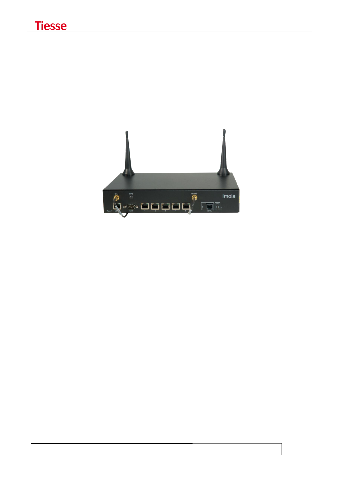
IMOLA ROUTER SERIES
IMOLA is a range of network devices that offers typical Router functions in both wired and wireless
configurations (supporting ISDN/HDSL/ADSL/VDSL/G.SHDSL/GBE on fixed networks and
GPRS/EDGE, UMTS/HSDPA/HSUPA/LTE connections on mobile networks). Imola is designed in order
to connect local and remote sites in particular when security, service availability and network
performance are of prime importance.
Figure 1: IMOLA Mod. 5262
IMOLA is based on 3 functional modules, not necessarily physically separate: a module containing
the main features; a module hosting protocol controllers and WAN interface; a power supply
module which may supply both an AC/DC converter (Internal Power Supply) and a DC/DC converter
(External Power Supply).
The main characteristics are:
Network Processor
64-256 MB RAM, depending on the model
512KB Boot Flash
16-256 MB Flash Memory for OS and applications, depending on the model
It also contains the following communication ports:
1 FE or GBR Ethernet (except for LX models, where there will be only one port FE). The GBE
port can optionally have a connector SFP
1 console port RS232 with DB9 male connector
1 ISDN S/T BRI with RJ 45 connector (only in some models)
1 integrated switch LAN up to 8 FE/GbE ports with VLAN 802.1q support (optional)
1 Wi-Fi port 802.11 b/g/n (optional)
1 ADSL/ADSL2+ with RJ11 connector (optional)
1 GSM/GPRS/EDGE/UMTS/HSDPA/HSUPA port (optional)
1 GSM/GPRS/EDGE/UMTS/HSDPA/HSUPA/LTE port (optional)
1 synchronous serial port with LFH 60 V.35 connector (optional)

Introduction
USER GUIDE
15
X
0
No mobile network connection
1
GPRS (models no longer in production)
2
GPRS / EDGE
3
GPRS / EDGE / UMTS / HSDPA
4
GPRS / EDGE / UMTS / HSDPA / HSUPA
5
GPRS / EDGE / UMTS / HSDPA / HSUPA / LTE
Y
0
1 Ethernet port present
1
2 Ethernet ports
2
5 switch Ethernet ports (4 ports in LX version)
3
1 Wi-Fi (besides Ethernet switch)
8
8 Ethernet ports1
Z
0
No WAN connection
1
ADSL
2
ADSL2+
3
HDSL
4
SHDSL
6
VDSL2
K
0
Ethernet ports FE 10/100 Mbps
2
Ethernet ports GBE 10/100/1000 Mbps
1
2 G.SHDSL ports that can be used in 2-Wire o 4-Wire mode
2 RS232 DCE ports with DB9F connector and/or DB25F (optional)
2 SFP optic port (optional)
4 ISDN BRI VoIP ports (optional)
4 FXS VoIP and 1 FXO port (optional)
In order to distinguish the different characteristics and communication interfaces, each model is
identified by the name Imola XYZK, where:
X identifies the type of WAN connection on mobile network
Y identifies the type of local network connection
Z identifies the type of WAN connection
K identifies the type of LAN port (FE or GBE)
The values are as follows:
Additional expansion cards can be mounted to provide:
asynchronous RS232 serial connectivity through two DB9 ports or a DB9 and a DB25 port,
both for connecting serial devices such as RTU, CBT, SCADA and various controllers (IKR)
direct connectivity on Fiber Optic via two SFP ports
- In the model with 8 Ethernet ports, the 6, 7 and 8 are always FE independently of the other 5, which may be the FE or GBE

Introduction
USER GUIDE
16
V.35 connection interface (IKH)
Wi-Fi connectivity (IKW)
For example:
the model 5200-IKR-IK2F has:
o LTE interface
o 1 FE port
o 5 FE switched/router port s
o 2 RS232 ports
o 2 SFP Fiber Optic port
The model 5262-IKH has:
o LTE interface
o 1 Gigabit Ethernet port
o 5 Gigabit Ethernet switched/routed ports
o 1 A/VDSL2 port
o 1 V.35 port
The model 5262-IKS has:
o LTE interface
o 1 Gigabit Ethernet port
o 5 Gigabit Ethernet switched/routed ports
o 1 A/VDSL2 port
o 1 G.SHDSL port
The model 5262-IKW has:
o LTE interface
o 1 Gigabit Ethernet port
o 5 Gigabit Ethernet switched/routed ports
o 1 A/VDSL2 port
o 1 b/g/n Wifi
These cards are called, respectively, IKR and IK2F and these become the suffix of the name of the
router.
Some models are also available with external power supply and called Imola LX. In this model the
ISDN BRI port is not present and the switch has 4 Fast Ethernet ports instead of 5. In other cases in
order to identify the generic model the name Imola Full is used.
It is possible to provide a DC/DC 9-36V supply power: in this case the router is called ImolaT.

LED general meaning
USER GUIDE
17
LED type
LED
COLOR
BEHAVIOUR
DESCRIPTION
Router On / Off
On
Green
On
The router is powered on
Ethernet interface
(2 LEDs integrated in
the connector)
Left
Yellow
Off
The interface is damage or the connection
is running at 10Mbps
On
The Ethernet interface is connected at
100Mbps
Right
Green
Blinking
LAN activity
ADSL/VDSL interface
(1 LED)
Imola XX20
Link
Green
Blinking slowly
Shows that the interface is ready to
establish a connection
Blinking fast
Shows that the communication with the
central has been established and the
connection is ongoing
On fixed
Connection established
ADSL interface
(3 LEDs)
Imola XX10
PW / ON
Green
On
ADSL internal modem correctly powered.
Link
Green
Blinking
Shows the sync phase with the central
On
Shows that the synch phase has been
successful
Data
Green
Blinking
Data traffic
ISDN interface
(2 LEDs integrated in
the connector)
Left
Yellow
On
Physical ISDN level is active (ongoing call)
Right
Green
On
Shows that at least one ISDN session is
active.
Note: while the system is booting, both LEDs are on. They turn off when the booting phase is finished.
Interface GPRS
(modem GPRS or EDGE
- models 1xx0 e 2xx0)
Link
Green
Blinking fast
Shows the sync phase with the central
Blinking slowly
1-2 seconds on: the connection has been
correctly established
On
GSM connection is active
Data
Green
On
GPRS connection is active and the
interface has obtained an IP address
Interface GPRS
(modem HSDPA or
UMTS - models 3xx0)
Link
Green
On
The connection is correctly established
Data
Green
On
GPRS connection is active and the
interface has obtained an IP address
HDSL interface
V35
Green
On
The router has detected the network
SHDSL interface
Link
Green
On
The SHDSL modem is correctly powered
and initialized
Data
Green
Blinking
Shows the sync phase with the central
Steady on
The sync phase was successful
LED GENERAL MEANING
Different LED indicators show the status of connection. The position of the LEDs and the related
labels can be different according to the various models.

LED general meaning
USER GUIDE
18
LED type
LED
COLOR
BEHAVIOUR
DESCRIPTION
Router On / Off
On
Green
Fixed on
Imola is on
Ethernet interface
Eth1 -1
Green
Fixed on
The connection is active
Eth1 -2
Eth1 -3
Eth1 -4
FE interface
FE
Green
Fixed on
The connection is active
GbE interface
GbE
Green
Fixed on
The connection is active
Wi-Fi interface
Wi-Fi
Green
Fixed on
The connection is active
xDSL interface
xDSL
Green
Slow Blinking
1sec. on / 1sec. off
Activating: the modem is waiting
for the connection
Fast Blinking
0.500 ms on
0.500 ms off
Handshaking
Fixed on
The connection is active
Mobile interface
4G/3G
Green
Fixed on
The port is configured via CLLI
and it is usable
Slow blink 1s on 5s off
Not active or searching for the
connection
Fast blink 0.5s on /
0.5s off
The connection is active
GSM
Off
No connection
Fixed on
The connection is active
ISDN interface
Link
Green
Fixed on
Physical ISDN level is active
(ongoing call)
AcT
Fixed on
Shows that at least one ISDN
session is active.
Imola 5260's LED

LED general meaning
USER GUIDE
19
FUNCTIONALITIES
Other functions may be associated to the communication services:
ACLs support
Authentication and accounting support via RADIUS
AAA support via Tacacs+
NAT/PAT functions
Stateful Firewalling functions
VRF-Lite support
VPN with IPSec 3DES Encryption
Tunnel GRE
L2TPv2 tunnel
L2TPv3 tunnel both static and dynamic
PPTP Tunneling
Open VPN Tunneling
Easy VPN Tunneling
Advanced Routing (Policy routing)
RIP, OSPF, BGP routing and BFD support
PIM protocol support (Protocol Independent Multicast) in Dense mode, Sparse mode and
Source Specific Multicast
IGMP Proxy and IGMP Snooping support
Band Optimization with QoS (Quality of Service)
VRRP support (Virtual Router Redundant Protocol)
Functions of IP SLA with Responder Time Reporter
SNMP v1/v2/v3
TR-069 support
Client and Server DHCP
Local and remote logging
Client and Server Telnet and SSH
Administration and control tools (ping, traceroute, debug ip packet, …)
The Command Line Interface (CLI), owned by Tiesse S.p.A., allows the configuration and
management of the system in a simple and guided way.
LED general meaning
USER GUIDE
20
X
1
GPRS
2
GPRS / EDGE
3
GPRS / EDGE / UMTS / HSDPA
4
GPRS / EDGE / UMTS / HSDPA / HSUPA
5
GPRS / EDGE / UMTS / HSDPA / HSUPA / LTE
Y
0
1 Ethernet FE 10/100 Mbps port
1
2 Ethernet FE 10/100 Mbps port
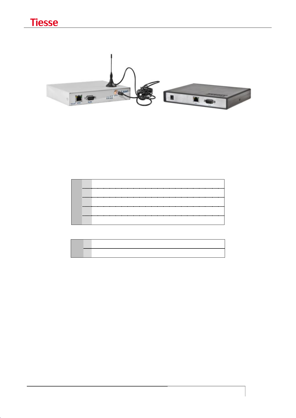
LIPARI MODELS
Lipari is another Tiesse‟s router model, which has equivalent functions to the routers of the Imola
series, but it only supports mobile connections. In the picture above you see two models of the
Lipari series.
It has a module of external power supply AC/DC 5Vdc / 1A.
As in the Imola models, in order to distinguish the different features and communication interfaces
each model is identified by the label Lipari XY00 where:
X identifies the type of WAN connection on mobile network present.
Y identifies the number of LAN Ethernet ports 10/100.
LED general meaning
USER GUIDE
21
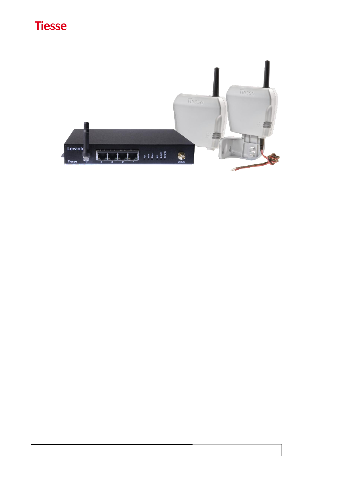
LEVANTO MODELS
Levanto models are functionally equivalent to Lipari‟s, the difference is about the RS232 ports that
Levanto have, which are used to connect serial devices like RTU, SCADA, etc.
Levanto 410 has a 3G port, a Ethernet port and a DB9 DCE serial port; in the factory configuration,
the serial port is used as console.
Levanto 441 has a 4G port, a Ethernet port and four RJ45 serial ports; it is equipped with an
external power supply AC/DC 5VDC/1A type. The serial port 1 (the first on the right) is used as
console while the others (2 – 3 and 4) are used to do the conversion from serial to TCP/IP.

LED general meaning
USER GUIDE
22
IMOLA E
Imola E system addresses the need to integrate the data and voice routing functionalities, both
wired and mobile, in a device that must be modular, configurable and highly reliable, even in
industrial environment which are subject to electromagnetic perturbation.
Imola E offers ina a single modular system the maximum integration between different
communication channels: copper and fiber optic Ethernet, ISDN BRI, serial WAN V.35 and E1, 3G /
4G, ADSL, G.SHDSL, interface to PSTN analog phones for voice routing with IP protocols on local and
geographic networks.
The modular architecture allows its evolution over time, integrating new functionalities and new
communication channels on a already consalidated system.
The automatic backup over ISDN or over radiomobile network (or any other secondary channel, like
satellite for example) and the presence of redundant power supplies ensure the continuity of
operation.
We particularly care about the immunity from electromagnetic perturbation, environment conditions
and safety reuglations.
Imola E is an evolution of the products of the serie Imola, it is the Tiesse Network Open Appliance,
based on RISC Network Processor and Linux platform, optimizes for networking.
Imola products are used as core components to produce LAN/WAN connectivity solutions where
security and integration of multiple ambient, protocols and transmitting channels are crucial.
The products in the Imola serie provides hardware/software functional blocks including router,
firewall, VPN server, LAN and WAN interfaces, asynchronous serial lines for terminal connections,
ISDN interfaces, ADSL2+, LTE/HSDPA/EDGE/GPRS, VoIP functionality, automatic backup channels for
the continuity of the service.
Depending on application requirements, it is also possible to evolve the product by introducing new
features through remote software upgrades, thus preserving investment and reducing operating
costs.
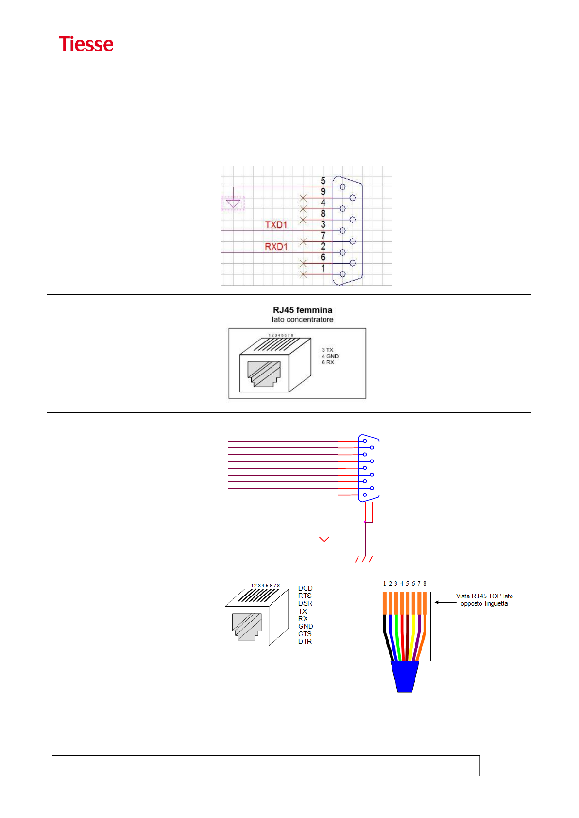
LED general meaning
USER GUIDE
23
Imola / Lipari
DB9 male connector
Imola
RJ45 connector
Levanto 310/410
DB9 female connector
Levanto 441
RJ45 connector
COM_DSR
COM_RTS
COM_CTS
COM_RI
GND 5 9
4 8 3
7
2
6
1
10
11
P1
DB9F SH
COM_DCD
COM_RXD
COM_TXD
COM_DTR
SERIAL CONNECTORS
To access the router you can use the console port, which can be different from model to model.
Below you find a scheme for the different kind of console port.

Accessing IMOLA
USER GUIDE
24
2
ACCESSING IMOLA
Access can be made via the console port with DB9 male connector on the front of Imola, with a
proper null modem cable, using any program of terminal emulation (HyperTerminal, Minicom,
Putty, ...) or via a Telnet connection to one of the IP addresses present on Imola.
Imola LX models have only a 4 ports integrated switch, each numbered 1 to 4. The factory
configuration, all the ports refers to a single IP address on the logical interface eth0.
The other models have a single Fast Ethernet port identified by the label eth0 and a 5 ports
integrated switch (8 in some models), where the ports are numbered 1 to 5 (or 8). In the factory
configuration all the switch ports refers to a single IP address and the logic interface is named eth1.
In case of direct connection to the single Ethernet port of Imola Full model (eth0 port) a LAN cross
cable should be used. Thanks to the auto-mdx function any kind of cable may be used in case of
connection to any port of the integrated switch.
Tiesse spa - IMOLA Interworking Unit
No Radius configured. Using Local authentication
login: root
Password:
local: Authentication OK
Service Type is: Administrative-User
Idle timeout is set to 3600 seconds
Connected Users:
ttyp1 root
You are logged on ttyp1
The configuration environment presents this prompt: username@hostname where username is the
login and hostname is the configurable name of the system. The service type (Administrative-User
or Login-User) indicates the user‟s privileges, the session inactivity timeout, the users connected
and the virtual tty used.
You can modify the timeout session by using:
idle <seconds>
where 0 means infinite.
This list can be checked any time through who command2:
root@Imola> who
Connected Users:
ttyp1 root
ttyp2 root
You are logged on ttyp2
root@Imola>
- Even though several users can be connected to the router, it is advisable that only one user modifies the configuration in
order to avoid undesirable effects.

Accessing IMOLA
USER GUIDE
25
SOFTWARE VERSION AND MODEL
It is possible to read the router‟s model through the command show model:
root@IMOLA> show model
Tiesse Imola 5262 Multiprotocol Router
The command show version shows the software‟s version.
root@IMOLA> show version
Imola version: 5.4.3-2
The version number adopts the naming convention: 5.x.y-N
The first number identifies the hardware platform used in the production.
The value of x indicates the major number, which changes in case of relevant functionality.
For example, with the support of protocol IPv6 it is possible to pass from release 4.3.1 to
release 4.4.0.
The value of y indicates the minor number, which increases when other independent
functionality, which do not affect other software‟s functions, are added. For example, with
the addition of the Tacacs support it is possible to pass from release 4.3.0 to release 4.3.1.
The suffix N indicates the build number. It increases in case of small bug-fixing which do
not require non-regression tests. For example, by making a correction in the module
managing IP SLA‟s functions it is possible to pass from release 4.3.1-0 to 4.3.1-1.
In addition to the router with version 5.x.y-N, we produced router whose version is 1.x.y-N type,
router with versions 2.xy-N type and 4.x.y-N version. There is no difference from a functional point
of view.
ACCESS VIA TTYS0 PORT
Cable Type: null-modem DB9
IMOLA Port: ttyS0 port
Application: Windows HyperTerminal (or similar)
ttyS0 port settings
Some models have the console with a RJ45 connector instead of DB9. The settings are the same.
When using the ttyS0 port to access Imola, the system used for the connection has to be configured
in the following manner:
Bits per second: 9600
Data bits: 8
Parity: none
Stop bit(s): 1
Flow Control: N.A. (Not Applicable)
Accessing IMOLA
USER GUIDE
26
eth0 port
eth1 port
IP Address
10.10.113.1
172.151.113.1
Netmask
255.255.0.0
255.255.0.0
Broadcast
10.10.255.255
172.151.255.255
Network Address
10.10.0.0
172.151.0.0
The following figure shows an example:
Tiesse spa - IMOLA Interworking Unit
login: root
Password: *********
Imola# cli
Service Type is: Administrative-User
Idle timeout is set to 600 seconds
Connected Users:
ttyS0 root
You are logged on ttyp1
ACCESS VIA ETH0 AND ETH1 PORTS
Cable Type: LAN (Ethernet type)
IMOLA Port: eth0 or eth1 port
Application: Telnet (or similar)
eth0/eth1 default settings
In models with a LAN integrated switch (IMOLA X2X0); the connection to eth1 port can be made via
any of the available ports in the switch.
USERNAME AND PASSWORD
In order to access Imola login and password need to be specified.
Factory configuration accepts the following login and associated password:
login: root
password: tiesseadm
It is possible to change the root user password thanks to the CLI command:
which in interaction modality asks to introduce the new password.
Further users can be added using the command:
change_password root
add_user <user_name>

Accessing IMOLA
USER GUIDE
27
which asks to specify the associated password too.
The command
set user <username> password <password>
allows you to create a user in non-interactive mode.
Users added through the add_user command are Login users, as well as the ones added via set
user command. The su command gives the possibility to pass from Login mode to Administrative
one. For example:
There are two types of users: Administrative-User and Login-User.
Administrative-User can execute any kind of CLI command, while Login users may only execute
a limited number of these commands, for example commands which modify the configuration are
not allowed, while the ones about displaying are allowed.
Tiesse spa - IMOLA Interworking Unit
No Radius configured. Using Local authentication
login: mario
Password:
local: Authentication OK
Service Type is: Login-User
Idle timeout is set to 3600 seconds
Connected Users:
ttyp0 mario
You are logged on ttyp0
mario@Imola# set hostname MyRouter
Command "set hostname MyRouter ..." not allowed for this user
mario@Imola# su root
Password:
root@Imola> set hostname MyRouter
Setting hostname to MyRouter
root@Imola> quit
mario@Imola#
mario@Imola# set eth1 ipaddr 3.3.3.3
Command "set eth1 ipaddr 3.3.3.3..." not allowed for this user
mario@Imola#
For example, if you access the router using the user "mario" and you try to run the command set
hostname in order to change the name of the router, the command fails due to the lack of the user
privileges. Using the su command and specifying the correct password it is possible to enter
Administrative mode with more privileges. The hostname can now be changed.
The quit command allows to go back to the previous user.
Pay attention to the last character of the prompt: the character # for Login User and the character >
for Administrative User.
The authentication mode may be configured via RADIUS protocol as described in the relative
chapter. In this case the RADIUS server determines which users have full rights and which users
have restrictions.

Accessing IMOLA
USER GUIDE
28
To view the list of the local users and their respective privileges (granted or revoked), you can use:
show user
GRANTING AND REVOKING PRIVILEGES
An Administrative User may give Login Users the possibility to execute certain commands generally
not allowed. In the same way, the Administrative User may revoke to an Administrative the
possibility to execute commands which are normally allowed.
grant-to <username> <command prefix>
executed by an Administrative User gives the user <username> (Login User), the possibility to
execute commands which begin with the specified prefix.
revoke-to <username> <command prefix>
executed by an Administrative User forbids the user <username> (Login User)) the possibility of
executing commands beginning with the specified prefix.
For example, the users "operator" and "technician" are respectively Login-User and AdministrativeUser. "Operator" can normally check the configuration but cannot change it, while "technician" can
make any modification without restrictions. The commands:
grant-to operator set eth1
revoke-to technician set isdn dialer ippp1
allow "operator" to configure the Ethernet port and denies "technician" the right to configure the
ISDN dialer.
In order to eliminate a privilege or a revocation the following commands are used:
no-grant-to <username> <command prefix>
no-revoke-to <username> <command prefix>
The <command prefix> string is the initial part of any configuration command.
It is necessary to pay attention when only one Administrative User exists, for example root. The
commands:
revoke-to root set
revoke-to root no-revoke
definitively deny root the right to execute any kind of configuration command.
PRIVILEGE LEVELS AND ENABLE COMMAND
Besides Administrative and Login users, when the access to the router is governed by a Tacacs+ (or
RADIUS) server, it is possible to manage different levels of privilege in order to establish which
commands may be executed.
It is possible to establish up to 15 levels of privilege, numbered from 1 to 4. The higher the level,
the more the available commands. It also exists the 15 level which corresponds to a condition of
superuser, i.e. a user without any kind of restriction on commands (similar to Administrative
user described in the previous section).

Accessing IMOLA
USER GUIDE
29
The level of privilege is established by the Authentication server used (RADIUS or Tacacs+). In the
first case it is necessary to configure a Custom attribute in the server (described in the RADIUS
section).
In the fault configuration there are 3 levels:
Level 0. The available commands are enable, exit and quit
Level 1. The available commands are those related to a Login user, that is only reading
commands without possibility of modifying the configuration
Level 15. The available commands are those related to an Administrative user. This means
that (potentially) all the commands are available.
The N level has all the privileges of lower levels, in order to pass from a level to another it is
necessary to know the password associated to that level.
The command:
set privilege level N <command prefix>
if executed by an authorized user, establishes that at N level all the commands starting with the
specified prefix can be executed. For example, by using:
set privilege level 3 set adsl
it is specified that users which have received a 3 level of privilege, can execute all the configuration
commands of the ADSL interface.
In order to eliminate the privileges previously set the command is:
set no-privilege level N <command prefix>
In order to check the current level of privilege the command is:
show privilege
In order to pass from a lower to a higher level a password should be associated with the higher
level.
The command which allows to associate the password with a certain level is:
set enable password level N
In an interactive modality it asks to enter the password. In order to eliminate the password the
command is:
set no-enable password level N
By this way the N level becomes inaccessible from lower levels.
In order to access a higher level the command is:
enable N
It asks to enter the password associated with the N level. If the password is correctly set, the user
can use all the commands associated with the N level.
For example, if a superuser has set the following commands in the router:
set privilege level 3 set eth1
set privilege level 3 set gprs
set enable password level 3

Accessing IMOLA
USER GUIDE
30
it is possible to grant a user with level of privilege 3 to configure the Ethernet and the mobile ports,
and a password has been associated with this level too.
The command used to set the password is interactive and it is here represented:
admin@IMOLA> set enable password level 3
16Changing password for $enable3$
New password: ********
Retype password: ********
Password for $enable3$ changed by root
In an Authentication server, Tacacs or RADIUS, a user named poor with the level of privilege 1 has
been configured. A connection to the router is made and the authentication occurs through the
poor user:
telnet 10.10.113.1
Trying 10.10.113.1...
Connected to 10.10.113.1.
Escape character is '^]'.
--------------------------------------------------------------
(IMOLA) (port 0)
--------------------------------------------------------------
login: poor
Password:
TACACS+: Authentication OK
Service Type is: Login-User
Privilege Level is: 1
Idle timeout is set to 3600 seconds
Connected Users:
pts/0 poor@IMOLA
You are logged on pts/0
poor@IMOLA#
A command to configure the IP address of the Ethernet interface is executed:
poor@IMOLA# set eth1 ipaddr 192.168.1.1
% Command "set eth1 ipaddr 192.168.1.1" not allowed for this user
poor@IMOLA#
The command fails. Another command is executed in order to access a higher level:
poor@IMOLA# enable 3
Password: ********
$enable3$@IMOLA#
$enable3$@IMOLA# show privilege
Current privilege level is 3
$enable3$@IMOLA#
At this point the command:
$enable3$@IMOLA# set eth1 ipaddr 192.168.1.1

Accessing IMOLA
USER GUIDE
31
is correctly executed.
In the end, the command disable brings back to the initial level:
$enable3$@IMOLA# disable
poor@IMOLA#
poor@IMOLA#
poor@IMOLA# show privilege
Current privilege level is 1
If the access to the router is governed by the Tacacs server, the control of the password of enable is
realized by the server. However, if you want to obtain the access to the router from the Tacacs
server and locally check the passwords of enable, it is necessary to set the command:
set enable local-authentication
with:
set enable no-local-authentication
the control is sent back to the Tacacs server.
ACCESS VIA SSH
The command:
set ssh2-enabled
enables the access to the router via SSHv2 protocol. As in the Telnet sessions the access is
governed by the RADIUS or Tacacs+ servers if correctly configured.
In order to disable the access the command is:
set no-ssh2-enabled
It is possible to load some authentication keys on the router (public or private), previously
generated on an external system (on Linux system you can use the command ssh-keygen).
The file that contains the private key must be called id_rsa.
The file that contains the public key must be called id_rsa.pub
These keys can be moved on the router using:
sshkey download id_rsa from <tftp-server>
while the command:
sshkey install
Activate them.
The command
sshkey install-pkey
installs only the public key.
The command:

Accessing IMOLA
USER GUIDE
32
sshkey save
saves the keys on a non-volatile memory so that they can be available at the router reboot.
PASSWORD RECOVERY PROCEDURE
If you are using a serial connection, it is possible to use a special login which allows to access
without asking a password, in order to recover the factory configuration.
The login value can be the default one or you can concur a specific value with your costumer, that
wil be used only for him.
On certain models of router, if you use a serial connection, you can apply as follow:
At the router prompt, press simultaneously the key “Shift” (uppercase button) and the key
“z”
When the prompt is up, type the commands:
setenv config factory
saveenv
boot
With those commands the router reset itself to the factory configuration and the previous settings
are lost.
REBOOT OF THE ROUTER
The router can be rebooted using the command:
reboot
After the reboot, all the unsaved changes (through the command save), will be lost.
A time programmed reboot can be configured, specifying after how many seconds this must be
done. The command is:
schedule-reboot wait N
The command prompt is returned to the user, so that other commands can be executed or to end
the current session.
The programmed reboot can be disabled with the command:
no-schedule-reboot
It is advisable not to make configuration saves when a time programmed reboot has been set.
DEFAULT SETTINGS
Imola default configuration includes:
eth0 address (service): 10.10.113.1/16
eth1 address (and integrated switch): 172.151.113.1/16
SNMP v1 and v2 enabled, with public community for read-only accesses and Tiesseadm for
read-write accesses.

Accessing IMOLA
USER GUIDE
33
syslog disabled
ADSL disabled
GPRS disabled
Dynamic Routing and tunneling disabled

IMOLA configuration
USER GUIDE
34
IMOLA CONFIGURATION
In order to configure Imola the operator has a character interface known as Command Line Interface
(CLI).
Using the CLI it is possible to configure, activate and check interfaces and available services
present on Imola.
CONFIGURATION PROCEDURE
The configuration of Imola includes the following phases:
configuration
check
parameters activation
storing
To configure and activate you can use commands with the prefix:
set
To check the status you can look at the LED indicators and also use the command with prefix:
show
In order to save the complete and checked configuration the command:
save
The command:
restore
is used to recover specific configurations.
There are three different types of configuration:
current saved started
The current configuration contains all the values set during configuration.
The saved configuration is that saved in Imola non-volatile memory using the save command and
will be used during the next boot.
The started configuration is that which was activated in the last boot operation. At the end of the
boot, before configuration begins, the three configurations are identical.
During the configuration and check phases, saved and started configurations are identical.
After the save command, the current configuration also becomes saved. Through this
configuration the device will be activated at the next boot.
It is possible to check the content of the three different configurations by using the command:
show config current|saved|started
or if you want to check the configuration of a single module the command is:
show config current|saved|started <module-name>

IMOLA configuration
USER GUIDE
35
It is always necessary to conclude the configuration and check phases by the save command, in
order to make permanent the values assigned to the different parameters.
It is also possible to manage the intermediate phases of configuration.
The CLI command set checkpoint allows the creation of an intermediate saving, named
checkpoint. It is useful in order to save a type of configuration in a certain moment. Using the
restore checkpoint command it is possible to recover the specific configuration saved.
For example:
set checkpoint step1
creates an intermediate saving which can be recalled at any time by using the command:
restore checkpoint step1
To learn how many checkpoint are set, use
show checkpoint-list
and to remove one:
set no-checkpoint <name>
To make the configuration changes effective, it is necessary to execute the save command and
make the reboot of the router.
The command:
sync-config
allows to accommodate the router to a specific configuration.
The specific configuration can be a default one (saved, started) or it can be loaded from a
properly uploaded command file.
The command syntax is:
sync-config <conf-file> immediately
sync-config <conf-file> in N seconds
where <conf-file> can be one of the keyword saved, started, or a file containing the
configuration commands to apply.
In this case you have to specify the absolute path of the file with its own extension (*.txt, *.cli, etc..).
The configuration can be applied:
immediately
after a selected time (N seconds)
after the next reboot of the router
sync-config <conf-file> on-next-reboot [<watch-ip> <tmout> <rstr>]
In case of next-reboot, the router will be rebooted with the saved configuration and immediately
after it applies the commands included into <conf-file>.
Some control parameters are:
<watch-ip>
after the new configuration is be applied, ICMP packets will be sent to the watch-ip IP address.

IMOLA configuration
USER GUIDE
36
<tmout>
Indicates the latency before starting the transmission of ICMP packets.
<rstr>
This parameter can be absent or it can be set to 1. In the latter case it indicates if a new reboot of
the router is necessary after the application of the new configuration.
This is the command scheme:
After the application of the configuration, the router waits <tmout> seconds. Then it transmits ICMP
packets to the <watch-ip> IP address. In case of no response, the previous configuration is
restored; otherwise the new configuration will be the current configuration, overwriting the
previous one. The <rstr> parameter indicates if a new reboot of the router is necessary after the
new configuration.
It is available the command
sync-config-checkpoint
that allows to align the status of the router to the configuration written in the checkpoint file; the
sintax is:
sync-config-checkpoint <checkpoint-name> immediately
sync-config-checkpoint <checkpoint-name> in N seconds
COMMAND-LINE INTERFACE (CLI) GUIDE
The Imola CLI has an online help which helps the user in formulating all the available commands
in a way which is syntactically and semantically correct.
Pressing the <TAB> key twice or the “?” character, all the available commands will be displayed,
followed by a brief description.
Command-line completion or display of available alternatives is possible using the <TAB> key.
When the command is incomplete a help function is automatically called: it provides all the
necessary information for a correct completion.
Tiesse spa - IMOLA Interworking Unit
No Radius configured. Using Local authentication
login: root
Password: *********
local: Authentication OK
Service Type is: Administrative-User
Idle timeout is set to 600 seconds
Connected Users:
ttyp0 recovery_user
root@Imola>
# download record show
add_user exit restore su
help traceroute
upload change_password
ping save version clear_counter
quit set who del_user

IMOLA configuration
USER GUIDE
37
reboot shell
root@Imola>
Figure 2: some of the available commands are displayed by pressing the <TAB> key twice or ? key
root@Imola> set ?
adsl Configure adsl
alias Configure secondary address
autocmd Configure Command executed automaticaly at boot time
backup Configure Backup procedure and criteria
banner Configure banner
bgp Configure BGP Protocol
ospf Configure OSPF Protocol
rip Configure RIP Protocol
eth0 Configure eth0 parameter
vrrp Configure VRRP Protocol
gre Configure GRE tunneling
....
....
root@Imola>
Figure 3: command-line completion and listing of parameters by pressing the <TAB> key.
root@Imola> set eth1 ?
set eth1 ipaddr Configure IP address
set eth1 broadcast Confgure Broadcast Address
set eth1 dhcp-client Enable DHCP Cleinte
set eth1 netmask Configure Netmask
set eth1 description Configure a description
set eth1 no-description
....
....
root@Imola>
Figure 4: online help
The basic rules for the setup of an interface or a service include the configuration and activation of
the configured parameters.
The commands are divided into 3 categories:
configuration command set <options>
display command show <options>
management and administration commands.
The command:
show version
displays the firmware version installed.
The command:
show system

IMOLA configuration
USER GUIDE
38
displays hardware and software details of the router, with the date and the version number.
It is very usual to set the configuration command by Copy&Paste action: you just have to copy the
configuration from a file on your computer and then you paste it in the router‟s cli.
If the commands line are several, like more than 20, and the connection to the router is made by a
serial port o via a slow connection, it can happen that some of the pasted lines returns. To avoid
this problem, you can use the command set-config which puts the router in a “acquiring
configuration” state and it corrects eventual errors. For example, see below:
root@IMOLA> set-config
Please Copy&Paste your configuration below and then
terminate with a single "." in a new line.
Your configuration will be imported and set as current.
To abort this session and let everything unchanged type "abort".
Put here your configuration:
MANAGING ENCRIPTED PASSWORDS
Introduction
Thanks to this feature you can view the password in encrypted form. The original passwords are
hidden from the user who is not authorized to know, in this way they can be used to set up similar
configurations on different routers.
This new feature is very useful, especially when it is needed to delegate others of the equipment
configuration without let them know the password of specific services.
The password encryption is applied to all system passwords, including password authentication,
secret key and Border Gateway Protocol neighbor password.
Configuration commands
The sequence to have a configuration with encrypted password is:
Apply the desired configuration using unencrypted password, in clear mode
Enable password encryption
Display the configuration
Command syntax
set crypted-passwords (on|off)
It allows you to enable (on) or disable (off) the display of the encrypted password.
When disabled, the password may be displayed in clear or using the notation * according to the
privileges of the user.
N.B.: The password will display in clear only if the same has been previously set in plain mode,
otherwise, you will see ever only encrypted regardless of whether or not the feature-crypted
passwords, if you used the encrypted mode.

IMOLA configuration
USER GUIDE
39
The commands that use encrypted passwords are prefixed with ‘crypted-„ (see example). You can
restore a configuration with passwords in clear mode by typing the command with the plaintext
passwords or resetting the module to the factory configuration.
Login/password PPP configuration:
set ppp login pppuser password tiesse
set crypted-passwords on
show config current
...
set ppp login pppuser crypted-password 6XY4+Gzy
Configuration of a RADIUS server:
set radius authhost 1.2.3.4
set radius secret 1.2.3.4 mypassword
set radius on
executing
set crypted-passwords on
show config current radius
you will get the follow display:
set radius authhost 1.2.3.4
set radius crypted-secret 1.2.3.4 0V6Povfs4/Q=
set radius on
Using the command „set radius crypted-secret 1.2.3.4 0V6Povfs4/Q=‟ on any Tiesse's
router, it will recognize and automatically encrypt the secret 'mypassword' for the RADIUS server
1.2.3.4.
To restore the plain mode you need to reset the module configuration:
restore factory radius

VoIP models
USER GUIDE
40
VOIP MODELS
There are available two different router models that, in addition to the network interfaces already
listed, they have both FXS and ISDN interface, to be used with analogical telephones and ISDN
switchboard. These models are Imola 0760-44 and Imola 0760-20:
Imola 0760-44 features are:
ADSL/VDSL2 port
Gigabit Ethernet port
4 ports Fast Ethernet switch
Wi-Fi b/g/n ports
FXO port
4 FXS ports
4 ISDN BRI ports
V.35 interface expansion slot
G.SHDSL interface expansion slot
while Imola 0760-20 has:
A/VDSL2 port
Gigabit Ethernet port
4 ports Fast Ethernet switch
Wi-Fi b/g/n ports
FXO port
4 FXS ports
The general functionality in terms of configuration, management, administration, routing etc. are
the same for all models of routers Imola.
How to configure the VoIP functionality is described in a separate chapter.

VoIP models
USER GUIDE
41
LED type
LED
COLOR
BEHAVIOUR
DESCRIPTION
Router On / Off
On
Green
Fixed on
Imola is on
Ethernet interface
Eth1 -1
Green
Fixed on
The connection is active
Eth1 -2
Eth1 -3
Eth1 -4
FE interface
FE
Green
Fixed on
The connection is active
GbE interface
GbE
Green
Fixed on
The connection is active
Wi-Fi interface
Wi-Fi
Green
Fixed on
The connection is active
xDSL interface
xDSL
Green
Slow Blinking
1sec. on / 1sec. off
Activating: the modem is waiting
for the connection
Fast Blinking
0.5s on / 0.5s off
Handshaking
Fixed on
The connection is active
FXS interface
1,2,3,4
Green
Fixed on
The port has been configured via
CLI and is ready to be used
FXO interface
FXO
Green
Fast Blinking 0.8 Hz -
0.625s on / 0.625s
off
The port is ready to be used
ISDN interface
1, 2, 3, 4
Green
Off
The port is not configured
1, 2
Fixed on
The port is configured as NT and
is ready to be used
1,2
0.8 Hz Blinking
0.625s on / 0.625s
off
The port is configured as TE and
is ready to be used
3,4
Fixed on
The port is configured as NT and
is ready to be used
LED MEANING - VOIP MODELS
Imola 0760-44-xx

VoIP models
USER GUIDE
42
LED type
LED
COLOR
BEHAVIOUR
DESCRIPTION
Router On / Off
On
Green
Fixed on
Imola is on
Ethernet interface
Eth1 -1
Green
Fixed on
The connection is active
Eth1 -2
Eth1 -3
Eth1 -4
FE interface
FE
Green
Fixed on
The connection is active
GbE interface
GbE
Green
Fixed on
The connection is active
Wi-Fi interface
Wi-Fi
Green
Fixed on
The connection is active
FXS interface
1,2,3,4
Green
Fixed on
The port has been configured via
CLI and is ready to be used
FXO interface
FXO
Green
0.8 Hz Blinking
0.625s on / 0.625s
off
The port is ready to be used
xDSL interface
xDSL
Green
Slow Blinking
1sec. on / 1sec. off
Activating
Fast Blinking
0.5s on / 0.5s off
Handshaking
Fixed on
The connection is active
Imola 5 BASE 0760-20

Ethernet interface
USER GUIDE
43
ETHERNET INTERFACE
INTERFACE CONFIGURATION
Imola Ethernet interfaces are called eth0 and eth1. The first is on the left and it is normally used as
a service port or as WAN port to connect to the network to external devices, leaving internal
network tasks to the eth1 interface. The LAN switch (if present) is connected to the eth1 port.
In LX models the 4-port LAN switch is connected to the eth0 port.
In order to set the IP address of an Ethernet interface the following CLI command is used:
set eth0|eth1 ipaddr <ip_address> [netmask <netmask> broadcast <broadcast>]
For example, in order to configure an eth0 interface with 10.10.9.1/16 IP address, specifying the
broadcast mode, the command is:
set eth0 ipaddr 10.10.9.1 netmask 255.255.0.0 broadcast 10.10.255.255
It is possible to enable the dynamic NAT over all outbound packets from the interface using:
set eth0 masquerade
You can limit the outgoing bandwidth to a maximum value with the command:
set eth0 bandwidth N
N is the value in Kbit/s.
It is possible to set an IPv6 address using the command:
set eth0 ipv6addr X:X::X:X/M
To set the MTU (Maximum Transfer Unit) value, use:
set eth0 mtu N
To activate the parameters:
set eth0|eth1 on
To deactivate an Ethernet interface:
set eth0|eth1 off
To configure the default gateway:
set last-resort-gateway <gw_ip_address>
To delete the default gateway:
set no-last-resort-gateway
For example, in order to set the address 10.10.254.254 as a default gateway the following
command line can be used:
set last-resort-gateway 10.10.254.254
In order to remove it, the command is:
set no-last-resort-gateway

Ethernet interface
USER GUIDE
44
The DHCP Client service can be set or removed for each Ethernet interface using the commands:
set eth0|eth1 dhcp-client
set eth0|eth1 no-dhcp-client
To specify the timeout of the table, you can use:
set eth0|eth1 arp-timeout N
In order to add an entry to the host list the following CLI command is used:
set host <ip_address> <HOSTNAME>
In order to remove it the command is:
set no-host <ip_address>
For example, in order to add host 10.7.10.10 with hostname MyHost:
set host 10.7.10.10 myhost
and in order to delete it from the list the command is:
set no-host 10.7.10.10
It is also possible to activate one or more secondary addresses on each Ethernet interface. These
secondary addresses are called alias. In order to set or remove an alias interface the following CLI
command is used:
set alias|no-alias <interface> ipaddr <alias_ip_addr> netmask <netmask>
For example, in order to set or remove the alias with IP address 10.10.10.3/24
on the eth0 interface the following command can be used:
set alias eth0 ipaddr 10.10.10.3 netmask 255.255.255.0
set no-alias eth0 ipaddr 10.10.10.3 netmask 255.255.255.0
If it is an IPv6 address the command is:
set no-alias eth0 ipv6addr X:X::X:X/M
It is possible to activate (or deactivate) a description of the Ethernet interface given back by the
SNMP agent (if configured and active), by querying the Mib_II ifDescr variable, using the
following commands:
set eth0|eth1 description|no-description <value>
It is possible to set the type of Ethernet connection avoiding the auto negotiation process:
set eth0|eth1 speed <my description>
where value can have one of the following values:
100BaseT4 100BaseTx-FD 10BaseT 10BaseT-HD
100BaseTx 100BaseTx-HD 10BaseT-FD 1000BaseT-FD 1000BaseT-HD
In case the switch is present, the connection parameters must be set by specific commands, which
are described in the relative switch section.
On Imola-LX models and Lipari as well, there is only the eth0 port.

Ethernet interface
USER GUIDE
45
3
DETECT-LINK-STATE COMMAND
You have to remember that, on some models, once configured, the Ethernet interface is always
available regardless of its operative status: the router always responds to possible requests arriving
on the IP address associated with the interface. In order to forbid these kinds of requests the
command is:
detect-link-state <interface-name>3
The command applies to the eth0 interface for Imola LX models and to eth1 for all the others.
You don‟t need to use detect-link-state if you have a Lan Splitted configuration.
The command apply on eth0 for router Imola LX and on eth1 for the others routers. It is not
necessary to use in case of a Lan Splitted (see the specific chapter).
DISPLAYING INTERFACE STATUS
In order to display the configuration of an interface, the following CLI command is used:
ifconfig eth0
which shows:
IP address
Netmask
Broadcast
MAC address
Static meters
In order to display the ARP table the command is:
show arp
In order to display IPv6 neighbour discovery protocol the command is:
show ipv6 neighbor
The command:
show ip interface brief
shows briefly the informations of all the network interfaces present.
root@IMOLA> show ip interface brief
show interface brief
Interface Status Protocol IP Address(s)/Description
--------- ------ -------- -------------------------
bri0 up down ISDN Channel 0 Status
bri1 up down ISDN Channel 1 Status
dummy0 down down Loopback Interface
eth0 up up 10.10.7.97/16
eth1 up up 172.151.113.1/16
eth1.10 up up 172.16.10.1/24
- In order to execute the command d uring the reboot of the router it is necessary to set the command set autocmd detect-link-state <ifname>

Ethernet interface
USER GUIDE
46
LED type
LED
COLOR
BEHAVIOUR
DESCRIPTION
Ethernet interface
(2 LEDs integrated in
the connector)
Left
Yellow
Off
The interface is damage or the
connection is running at 10Mbps
On
The Ethernet interface is connected at
100Mbps
Right
Green
Blinking
LAN activity
eth1.20 up up 172.16.20.1/24
The alias set on the Imola router can be shown using the CLI command:
show alias
ETHERNET LEDS MEANING
The RJ45 connector of the Ethernet interface has two LEDs indicators: one yellow on the left and
one green on the right.
TRIGGER ETHERNET
It is possible to define actions to be performed when there are changes of the status on the
Ethernet interface using the commands:
set trigger eth0 up <action>
set trigger eth0 down <action>
set trigger eth1 up <action>
set trigger eth1 down <action>
where <action> may be any CLI command supported by Imola. A sequence of actions may be
configured using a series of commands:
set trigger eth0 up <action1>
set trigger eth0 up <action2>
The execution of the actions follows the order previously set. For example, using the commands:
set trigger eth0 up logger Ethernet0 is up
set trigger eth0 down logger Ethernet0 is down
a message indicating a change in the status of the eth0 interface is logged.
Triggers may be deleted using the commands:
set no-trigger eth0 up <action>
set no-trigger eth0 down <action>
DHCP CLIENT TRIGGER
When a DHCP Client is configured it is possible to define actions to be performed when an IP
address is acquired and/or released using the commands:
set trigger dhcp up <action>

Ethernet interface
USER GUIDE
47
set trigger dhcp down <action>
where <action> is any CLI command supported by Imola. The execution of the actions follows the
order previously defined. For example, using the commands:
set trigger dhcp up logger We got an address
set trigger dhcp up ip route add 131.151.10.12 via 10.10.254.254
set trigger dhcp down logger Ethernet is not ready
when an IP address is acquired a message is logged and a static route to a host is added. When the
address is released a further message is logged. Triggers may be deleted using the commands:
set no-trigger dhcp up <action>
set no-trigger dhcp down <action>
ETHERNET PORT MANAGEMENT: MII-TOOL/ETHTOOL
The mii-tool command checks or sets the status of the eth0 and eth1 Fast Ethernet interfaces
and of the 5 interfaces of the integrated switch (eth1, eth2, eth3, eth4 and eth5).
The command is mostly used for evaluation purposes.
By using the appropriate options, the functionalities offered by the command are:
auto negotiation restart
set the port speed at a specific value
execute the negotiation restart specifying the port speed
modification of crossover functionality of the switch ports
monitoring the port status
The operative modality of the command is:
mii-tool [<option>] [<parameter>] <interface>
The options and accepted parameters are shown with:
mii-tool –help
The models that provide Gigabit Ethernet ports provide also the command ethtool, whose enabled
options are showrn with:
ethtool –help
Both commands can be used by SuperUser users; any changes applied to the ports configuration
will be lost at the next reboot.

POE model
USER GUIDE
48
POE MODEL
The router Imola 4860-IKW-POE is the one that provides an Ethernet Power Supply (POE) interface.
Its features are:
3G port (4G optional)
1 Gigabit Ethernet port
1 Switch with 8 FE ports
1 ADSL/VDSL port
1 Wi-Fi port
1 Ethernet Power Supply (PSE) port
The PSE port, according to the IEEE 802.3af/t, has to its ends a supply voltage from 21 to 57 V.
The following chapter shows how to configure the POE interface. The other interfaces settings are
described in the pertinent sections of this User Guide.

Ethernet Power Supply Interface
USER GUIDE
49
ETHERNET POWER SUPPLY INTERFACE
CONFIGURATION
The Ethernet Power Supply is called eps0.
To configure the IP address, you have to type:
set eps0 ipaddr <ip_address> [netmask <netmask> broadcast <broadcast>]
It is possible to enable a dynamic NAT on all the eps0 outbound packets with:
set eps0 masquerade
If you want to limit the outgoing bandwidth to a maximum value by using:
set eps0 bandwidth N
where N is expressed in Kbit/s.
You can set an IPv6 address with:
set eps0 ipv6addr X:X::X:X/M
To set the MTU value, use:
set eps0 mtu N
To apply all the previous settings, you have to execute the command:
set eps0 on
The configuration described above is applied in case it has been explicitly done the LAN splitting
(see the specific chapter). If not, the eps0 port is managed as any port inherent to the switch.

ISDN interface
USER GUIDE
50
ISDN INTERFACE
ISDN INTERFACE: CONFIGURATION COMMANDS
The Imola ISDN interface can be used to activate temporary communication circuits between two
terminal points (for example between 2 Imola boxes). The configuration is based on dialer maps.
A dialer map is a logic interface which allows a connection (incoming or outgoing) with a remote
user.
Factory configuration of Imola includes 2 dialer maps:
ippp0 accepts incoming calls
ippp1 allows outgoing calls
Outgoing calls can be made either automatically or manually. Automatic calling allows Imola to act
as a dial on demand router.
The basic parameters required for dialer map configuration are:
call handling, either incoming or outgoing (in the former case the dialer only accepts
incoming calls, in the latter case the dialer only allows outgoing calls)
method for making outgoing calls, either automatic or manual
telephone number (for outgoing calls)
login and password for authentication of outgoing calls
login and password for authentication of incoming calls
In order to make automatic outgoing calls an IP interface must be configured and associated with
the outgoing dialer map.
Outgoing calls will be activated only when the routing process discovers packets ready for
transmission on ISDN interface.
The configuration of a dialer map (for example dialer ippp0) which only accepts incoming calls
can be set using the following commands:
set isdn dialer ippp0 eaz all
set isdn dialer ippp0 in-number <value> [<value>]
set isdn dialer ippp0 accept-remote-ip
set isdn dialer ippp0 dialmode manual
set ppp login <user> password <password>
set isdn dialer ippp0 on
The command
set isdn dialer ippp0 eaz <all|number>
sets the telephone number for incoming connections: only incoming calls to this number will be
accepted. The value all allows calls to any number.
If a non-existent telephone number (e.g. 999999) is configured, the dialer map will reject all the
incoming calls.
set isdn dialer ippp0 in-number <value> [<value>]

ISDN interface
USER GUIDE
51
allows to specify a list of permissible callers from which accepting ISDN calls (Calling Line
Identification).
set isdn dialer ippp0 no-in-number
allows to accept calls from any caller.
set ppp login <user> password <password>
can be used to populate the user authentication database.
The database will be used during the authentication of incoming and outgoing calls.
In order to verify the dialer configuration just set, the command is:
show interface isdn dialer ippp0
The output is shown in the following figure:
root@Imola> show interface isdn dialer ippp0
Current setup of interface 'ippp0':
EAZ/MSN: *
Phone number(s):
Outgoing: 0125629552
Incoming:
Dial mode: manual
Secure: off
Callback: off
Reject before Callback: off
Callback-delay: 5
Dialmax: 1
Hangup-Timeout: 60
Incoming-Hangup: on
ChargeHangup: off
Charge-Units: 0
Charge-Interval: 0
Layer-2-Protocol: hdlc
Layer-3-Protocol: trans
Encapsulation: syncppp
Login: pppuser
Accept Remote IP: yes
Set Local IP: no
Default Route: no
Masquerade: no
---------------------------------------
ippp0 is not connected
8: ippp0: <POINTOPOINT,NOARP,UP> mtu 1500 qdisc pfifo_fast qlen 30
link/ppp
RX: bytes packets errors dropped overrun mcast
0 0 0 0 0 0
TX: bytes packets errors dropped carrier collsns
0 0 0 0 0 0
The configuration of a dialer map which can only make outgoing calls can be set with the following
commands:
set isdn dialer ippp1 eaz 999999

ISDN interface
USER GUIDE
52
set isdn dialer ippp1 out-number <number>
set isdn dialer ippp1 login <user> password <passwrd>
set isdn dialer ippp1 huptimeout 120
set isdn dialer ippp1 ipaddr 1.1.1.1 nexthop 2.2.2.2
set isdn dialer ippp1 masquerade
set isdn dialer ippp1 accept-remote-ip
set isdn dialer ippp1 no-accept-local-ip
set isdn dialer ippp1 dialmode manual
set isdn dialer ippp1 default-route
set isdn dialer ippp1 on
The command
set isdn dialer ippp1 eaz <all|number>
is used to configure the telephone number which will only accepts incoming connections: only
incoming calls to this telephone number will be accepted.
The value all accepts incoming calls from any telephone number.
If a non-existent number (e.g. 999999)is configured, the dialer map will reject all incoming calls. So
the dialer ippp1 is only used for outgoing calls.
set isdn dialer ippp1 out-number <number>
configures the number to be called by the dialer map.
set isdn dialer ippp1 login <user>
is used to configure the user which will be used for authentication during the connection to the
telephone number.
set isdn dialer ippp1 ipaddr 1.1.1.1 nexthop 2.2.2.2
configures the IP interface associated with the outgoing dialer map.
If the addresses are assigned by the remote system the following format can be used: set isdn
dialer ippp1 ipaddr 0.0.0.0
set isdn dialer ippp1 masquerade
is used to send IP packets using as IP source address the local address associated with the dialer;
i.e. all the NATP operations will be made on the dialer interface.
set isdn dialer ippp1 accept-remote-ip
and
set isdn dialer ippp1 accept-local-ip
establish the method through which the addresses on the ippp1 interface will be assigned. This
function is described in detail later.
set isdn dialer ippp1 dialmode manual
is used to define the method of call activation: manual allows manual activation through the
command isdnctrl dial ippp1 manual; auto allows automatic activation of the ISDN call when
there is the first transmission request on the ippp1 interface.
set isdn dialer ippp1 default-route

ISDN interface
USER GUIDE
53
is used to configure a default route on the dialer ippp1. This route will be activated only in case of
automatic dialling (set ISDN dialer ippp1 dialmode auto) or when a call is established.
How to verify the configuration of an activated dialer:
root@Imola> show interface isdn dialer ippp1
Current setup of interface 'ippp1':
EAZ/MSN: 999
Phone number(s):
Outgoing: 0125629552
Incoming:
Dial mode: manual
Secure: off
Callback: off
Reject before Callback: off
Callback-delay: 5
Dialmax: 1
Hangup-Timeout: 60
Incoming-Hangup: on
ChargeHangup: off
Charge-Units: 0
Charge-Interval: 0
Layer-2-Protocol: hdlc
Layer-3-Protocol: trans
Encapsulation: syncppp
Login: pppuser
Accept Remote IP: yes
Set Local IP: no
Default Route: no
Masquerade: no
---------------------------------------
ippp1 is not connected
9: ippp1: <POINTOPOINT,NOARP,UP> mtu 1500 qdisc pfifo_fast qlen 30
link/ppp
RX: bytes packets errors dropped overrun mcast
0 0 0 0 0 0
TX: bytes packets errors dropped carrier collsns
0 0 0 0 0 0
It is also possible to use both ISDN channels on a single logical connection (multilink connection). In
order to enable the multilink connection the following commands can be used:
set isdn dialer ippp1 multi-link
The second channel, called slave, must be activated when the master channel connection is
activated. The following command is used for this operation:
set trigger isdn up isdnctrl addlink ippp1
The slave channel will be automatically disconnected when the master channel is disconnected.
When the master channel is activated it is possible to verify the activation of the two channels:
root@Imola> isdnctrl list ippp1
Current setup of interface 'ippp1':

ISDN interface
USER GUIDE
54
EAZ/MSN: 999
Phone number(s):
Outgoing: 0125201010
Incoming:
Dial mode: manual
Secure: off
Callback: off
Reject before Callback: off
Callback-delay: 5
Dialmax: 1
Hangup-Timeout: 60
Incoming-Hangup: on
ChargeHangup: off
Charge-Units: 0
Charge-Interval: 0
Layer-2-Protocol: hdlc
Layer-3-Protocol: trans
Encapsulation: syncppp
Slave Interface: ippp62
Slave delay: 10
Slave trigger: 6000 cps
Master Interface: None
Pre-Bound to: Nothing
PPP-Bound to: 1
root@Imola> show interface isdn status
ISDN Status and Statistics:
irq=28 io=24000000 led=25000000
link status = up, chan B1 status = active, chan B2 status = active
link up = 00000009, link down = 00000009
chan B1 activations = 00000008, chan B1 deactivations = 00000007
chan B2 activations = 00000007, chan B2 deactivations = 00000006
D-frames rcvd = 00000533, D-frames sent = 00000188, D-rxowf = 00000000
B1-frames rcvd = 00000350, B1-frames sent = 00000172, B1-rxowf = 00000000
B2-frames rcvd = 00000056, B2-frames sent = 00000056, B2-rxowf = 00000000
The sub addressing mode can be configured both for incoming and outgoing calls.
In order to accept only incoming calls with subaddress 400 the command is:
set isdn dialer ippp0 eaz *.400
In order to make outgoing calls to a specific number (e.g. 0125230544) associating subaddress
500 the command is:
set isdn dialer ippp1 out-number 0125230544.500
If the router is connected to point-to-point ISDN lines rather than to point-to-multi-point lines, it is
necessary to set the command:
set isdn mode point-to-point
The command:
set isdn mode multi-point
sets multi-point mode.
Here follow some configuration examples of the different methods of address assignment of the
ippp1 interface:

ISDN interface
USER GUIDE
55
local and nexthop addresses both assigned by Imola
local and nexthop addresses both assigned by remote system (RAS)
Imola defines its own address and RAS defines nexthop address.
The following commands are common to the three examples:
set isdn dialer ippp1 eaz 999999
set isdn dialer ippp1 out-number 0125230544
set isdn dialer ippp1 login isdnuser password isdnpasswd
set isdn dialer ippp1 huptimeout 120
set isdn dialer ippp1 masquerade
set isdn dialer ippp1 dialmode auto
set isdn dialer ippp1 default-route
Both local and nexthop addresses assigned by Imola
set isdn dialer ippp1 ipaddr 1.1.1.1 nexthop 1.1.1.2
set isdn dialer ippp1 no-accept-remote-ip
set isdn dialer ippp1 accept-local-ip
set isdn dialer ippp1 on
Both before and after the call the ISDN interface is as follows:
root@Imola> show interface isdn dialer ippp1 statistics
19: ippp1: <POINTOPOINT,NOARP,UP> mtu 1500 qdisc pfifo_fast qlen 30
link/ppp
RX: bytes packets errors dropped overrun mcast
311 22 0 0 0 0
TX: bytes packets errors dropped carrier collsns
305 22 0 0 0 0
inet 1.1.1.1 peer 1.1.1.2/32 scope global ippp1
Both local and nexthop addresses assigned by remote system (RAS):
set isdn dialer ippp1 ipaddr 0.0.0.0
set isdn dialer ippp1 accept-remote-ip
set isdn dialer ippp1 no-accept-local-ip
set isdn dialer ippp1 on
After the activation of the ISDN session ippp1 interface is as follows:
root@Imola> show interface isdn dialer ippp1 statistics
19: ippp1: <POINTOPOINT,NOARP,UP> mtu 1500 qdisc pfifo_fast qlen 30
link/ppp
RX: bytes packets errors dropped overrun mcast
311 22 0 0 0 0
TX: bytes packets errors dropped carrier collsns
305 22 0 0 0 0
inet 151.25.132.24 peer 151.6.131.63/32 scope global ippp1
Local address assigned by Imola and nexthop address assigned by RAS
set isdn dialer ippp1 ipaddr 1.1.1.1

ISDN interface
USER GUIDE
56
set isdn dialer ippp1 accept-remote-ip
set isdn dialer ippp1 accept-local-ip
set isdn dialer ippp1 on
The following command allows to verify the call history of incoming and outgoing calls:
root@Imola> show interface isdn history
--------------------------------------------------------------------------
Call Calling Called Sec. Setup Term. Txed Rxed
Type Number Number Used Time Cause Bytes Bytes
-------------------------------------------------------------------------In 125230544 125633581 32,480 8 - 223 223
Out 123456789 0125201010 0,990 166 16 181 154
Out 12345678 0125201010 0,990 166 16 181 154
Out 12345678 0125201010 0,290 128 16 0 0
Out 12345678 0125201010 12,550 157 16 181 262
Out 12345678 0125201010 12,220 155 16 181 262
Out 12345678 0125629552 N/A - 146 0 0
Out 12345678 0125629552 N/A - 146 0 0
The following fields are shown:
Call Type (incoming/outgoing)
Calling Number incoming call number
Called Number outgoing call number
Sec. Used line occupancy
Setup Time duration setup time
Term. Cause disconnection cause code
Txed Bytes/Rxed Bytes transmitted and received bytes
The value of the code shown in the field Term.Cause identifies the modality of call termination: if
the disconnection occurs as a result of a remote case, the termination code will be higher than 128.
show interface isdn active-calls
shows the calls currently active. It is possible to activate a description of the ISDN interface, given
back by the SNMP agent (if configured and active) by querying the Mib_II ifDescr variable
through the command:
set isdn description <value>
It is also possible to configure different messages for each dialer:
set isdn dialer ippp0 description <value>
The native command isdnctrl, described later in the manual, can be used to directly manage the
ISDN dialers.
ISDN LEDS MEANING
The status of the ISDN interface is indicated by 2 LEDs on the connector: one yellow on the left and
one green on the right.

ISDN interface
USER GUIDE
57
LED type
LED
COLOR
BEHAVIOUR
DESCRIPTION
ISDN interface
(2 LEDs integrated in
the connector)
Left
Yellow
On
Physical ISDN level is active (ongoing
call)
Right
Green
On
Shows that at least one ISDN session
is active.
Note: while the system is booting, both LEDs are on. They turn off when the booting phase is finished.
4
ISDN TRIGGER
It is possible to execute some actions when an ISDN call is activated or deactivated by using the
commands4:
set trigger isdn up <action>
set trigger isdn down <action>
where <action> can be any CLI command supported by Imola. A sequence of actions is
configured with a series of commands:
set trigger isdn up <action1>
set trigger isdn up <action2>
set trigger isdn up <actionN>
The execution of the actions follows the same order through which they were set.
For example the following commands:
set trigger isdn up ip route add 12.12.12.12 dev ippp1
set trigger isdn up logger –r 10.10.1.212 ISDN is up
set trigger isdn down ip route del 12.12.12.12 dev ippp1
set trigger isdn down logger –r 10.10.1.212 ISDN is down
establish a static route towards host 12.12.12.12 and send a log message “ISDN is up” when the
ISDN connection is activated. When the ISDN session is terminated the route is eliminated and a log
message “ISDN is down” is sent.
The following commands are used to delete a trigger:
set no-trigger isdn up <action>
set no-trigger isdn down <action>
VERIFYING ISDN SESSION
The command:
isdnchat <phone-number>
activates a Q.931 session without triggering the authentication phase PPP. It is useful to verify if the
only telephone line is working.
The command:
- The trigger commands are effect ive only on the ippp1 dialer map and have no effects when the ippp0 dialer is active.

ISDN interface
USER GUIDE
58
isdnping <ip-address>
activates an outgoing ISDN call on the ippp1 dialer but no ISDN trigger will be executed.
It activates an outgoing ISDN connection using the ippp1 dialer parameters and executes a series of
ping packets towards the specified IP address without the use of “ISDN up” and “ISDN down”
triggers.
A usage example with accepted outgoing call:
root@IMOLA> isdnping 85.34.166.21
Dialing of ippp2 triggered
PING 85.34.166.18 (85.34.166.18) from 151.71.17.73 ippp2: 56(84) bytes of data.
64 bytes from 85.34.166.18: icmp_seq=0 ttl=56 time=212.459 msec
--- 85.34.166.18 ping statistics --1 packets transmitted, 1 packets received, 0% packet loss
round-trip min/avg/max/mdev = 212.459/212.459/212.459/0.000 ms
PING 85.34.166.18 (85.34.166.18) from 151.71.17.73 ippp2: 56(84) bytes of data.
64 bytes from 85.34.166.18: icmp_seq=0 ttl=56 time=255.972 msec
64 bytes from 85.34.166.18: icmp_seq=1 ttl=56 time=185.896 msec
64 bytes from 85.34.166.18: icmp_seq=2 ttl=56 time=93.655 msec
64 bytes from 85.34.166.18: icmp_seq=3 ttl=56 time=89.054 msec
64 bytes from 85.34.166.18: icmp_seq=4 ttl=56 time=82.312 msec
64 bytes from 85.34.166.18: icmp_seq=5 ttl=56 time=189.865 msec
64 bytes from 85.34.166.18: icmp_seq=6 ttl=56 time=268.800 msec
64 bytes from 85.34.166.18: icmp_seq=7 ttl=56 time=424.999 msec
64 bytes from 85.34.166.18: icmp_seq=8 ttl=56 time=88.148 msec
64 bytes from 85.34.166.18: icmp_seq=9 ttl=56 time=171.538 msec
--- 85.34.166.18 ping statistics --10 packets transmitted, 10 packets received, 0% packet loss
round-trip min/avg/max/mdev = 82.312/185.023/424.999/103.606 ms
ippp2 hung up
a usage example with rejected outgoing call:
root@IMOLA> isdnping 85.34.199.23
Dialing of ippp2 triggered
PING 85.34.199.23 (85.34.199.23) from 151.71.17.73 ippp2: 56(84) bytes of data.
--- 85.34.199.23 ping statistics --1 packets transmitted, 0 packets received, 100% packet loss
PING 85.34.199.23 (85.34.199.23) from 151.71.17.73 ippp2: 56(84) bytes of data.
--- 85.34.199.23 ping statistics --1 packets transmitted, 0 packets received, 100% packet loss
PING 85.34.199.23 (85.34.199.23) from 151.71.17.73 ippp2: 56(84) bytes of data.
--- 85.34.199.23 ping statistics --10 packets transmitted, 0 packets received, 100% packet loss
ippp2 hung up

ISDN interface
USER GUIDE
59
5
ISDN TRAFFIC CONTROL
The router can be configured in order to make a traffic control on the ISDN interface. In particular it
is possible to configure a threshold value and trigger events when the traffic in a given unit of time
is higher or lower than the defined threshold5.
set isdn traffic-control input-threshold <N>
the value of N bytes represents the threshold value for incoming traffic.
set isdn traffic-control output-threshold <N>
The value of N bytes represents the threshold value for outgoing traffic.
set isdn traffic-control timer-unit <N>
The value of N seconds represents the frequency of the check.
set isdn traffic-control mode or|and
Defines whether traffic control is about the input or the output threshold, or both.
set isdn traffic-control prewait <N>
Represents a waiting time (expressed in seconds) before starting the traffic control.
set isdn traffic-control on|off
Activates/deactivates traffic control
In order to activate the second ISDN channel the commands are usually used together with the
command set trigger isdn-tc. This is clarified in the following example:
set isdn traffic-control input-threshold 30000
set isdn traffic-control output-threshold 20000
set isdn traffic-control mode or
set isdn traffic-control timer-unit 10
set isdn traffic-control on
set trigger isdn-tc up isdnctrl addlink ippp1
set trigger isdn-tc down isdnctrl removelink ippp1
set trigger isdn up set isdn traffic-control on
set trigger isdn down set gprs traffic-control off
Traffic control is activated when the ISDN session starts and it is deactivated when the session ends.
It is set a threshold value of 30 Kbytes for incoming traffic and a threshold value of 20Kbytes for
outgoing traffic. The control is made every 10 seconds.
If in 10 seconds either incoming or outgoing traffic exceeds the threshold value, the
command specified by the set isdn-tc up trigger is executed. This activates the second ISDN
channel. Otherwise, if in 10 seconds traffic is lower than the threshold values, the command
specified by the trigger gprs-tc down trigger set is executed.
Sometimes it may be necessary to automatically activate the ISDN call only on the recognition of
special packages. To do so, type
set isdn-dial-control on
- Traffic control commands are effective only on the ippp1 di aler map and have no influence when the ippp0 dialer is active.

USER GUIDE
60
then, using the iptables command, you can set the filter on specific traffic. The iptables
command is well explained in its chapter, but below you will find some example for the case we just
described above.
To activate the ISDN session only when packets HTTP transit on the router:
set isdn-dial-control on
set iptables -A FORWARD -o ippp1 -p tcp --dport 80 -j QUEUE
To activate the ISDN session only when you do a ping command from the router toward a host:
set isdn-dial-control on
set iptables -A OUTPUT -o ippp1 -p icmp -d 10.10.10.10 -j QUEUE
To activate the ISDN session on the UDP traffic and on TCP traffic toward a host:
set isdn-dial-control on
set iptables -A FORWARD -o ippp1 -p udp -j QUEUE
set iptables -A FORWARD -o ippp1 -p tcp -d 10.10.10.10 -j QUEUE
To close the session, having set a timeout and when there is no more packets of the specified
traffic:
set isdn dialer ippp1 huptimeout N

ADSL interface
USER GUIDE
61
ADSL INTERFACE
CONFIGURATION
Imola XX10 models only support ADSL connections, while XX20 models support both ADSL and
ADSL2+ connections.
In ADSL connections the maximum bandwidth is:
downstream speed up to 8 Mbps
upstream speed up to 1 Mbps
In ADSL2+ connection the maximum bandwidth is:
downstream speed up to 24 Mbps
upstream speed up to 3.5 Mbps
A maximum of 8 PVCs (Permanent Virtual Circuit) is supported.
Conformity to the following standards:
ADSL: G.992.1 (G.dmt) - Annex A (ADSL over POTS), G992.2 (G.lite), ANSI T1.413 issue 2
ATM: ITU T-I.361, ITU T.I.363.5, ITU T-I.432, ITU T.I.610, ITU T-I.731
RFC 2684 (former RFC 1483 Multiprotocol over ATM)
RFC 2364 (PPP over ATM)
RFC 2516 (PPP over Ethernet)
In Imola XX20 models the following standards are also supported:
G.992.3 annexA, B, I, J, L (extended reach), M (double upstream)
G.992.4 – g.Lite.bis
G.992.5 annexA, B, C, I, J, M
It is possible to configure and activate the ADSL link by using CLI commands.
The command
set adsl on
activates the ADSL interface.
The command
set adsl off
deactivates the ADSL interface
The command
set no-adsl
deactivates the ADSL interface and disables the configuration.
Before the activation, the ADSL interface must be configured according to the contractual values
provided by the Service Provider.
In order to define the encapsulation type the command is:

ADSL interface
USER GUIDE
62
6
set adsl encap pppoa-llc|pppoa-vcmux|pppoe-llc|pppoe-vcmux rfc1483-llc|rfc1483-vcmux
In order to configure the number and type of PVC the command is:
set adsl pvc_number <value>
set adsl pvc atmX vpi <value> vci <value>
pvc_number can have a maximum value of 86 and atmX will be atm0, atm1,…atm7. The default
value of pvc_number is 1.
In order to configure vpi (value 8) and vci (value 35):
set adsl pvc atm0|…|atm7 vpi <value> vci <value> [pcr <value>]
If the encapsulation type is rfc1483-vcmux or rfc1483-llc (protocols described in RFC 1483,
Multiprotocol Encapsulation over ATM Adaptation Layer 5) it is necessary to define an IP address
through the command:
set adsl pvc atm0|…|atm7 ipaddr <value>
To remove the IP address:
set adsl pvc atm0|…|atm7 no-ipaddr
Otherwise, according to the information received from the Service Provider, the following
commands could be used:
set adsl pvc atm0|…|atm7 ipaddr <value>
set adsl pvc atm0|…|atm7 nexthop
set adsl pvc atm0|…|atm7 netmask <value>
set adsl pvc atm0|…|atm7 mtu <value>
In order to assign an IPv6 address the command is:
set adsl pvc atm0|…|atm7 ipv6addr X:X::X:X/M
A default route could be required:
set adsl pvc atm0|…|atm7 default-route
To enable NAT functions:
set adsl pvc atm0|…|atm7 masquerade
And to remove the options:
set adsl pvc atm0|…|atm7 no-ipaddr
set adsl pvc atm0|…|atm7 no-nexthop
set adsl pvc atm0|…|atm7 no-mtu
set adsl pvc atm0|…|atm7 no-default-route
set adsl pvc atm0|…|atm7 no-masquerade
When PPPoA (PPP over ATM) or PPPoe (PPP over Ethernet) encapsulation types are used, the login
and password for authentication must be defined:
set adsl login <value> password <value>
It is possible to configure the type of ATM traffic per PVC as follows:
- PPPoA and PPPoE connections can on ly have a single PVC.

ADSL interface
USER GUIDE
63
set adsl pvc atm0|…|atm7 service <service-type>
where service-type can be UBR, CBR, VBR or RTVBR. For the UBR and CBR traffic, it is possible to
specify a PCR value (Peak Cell Rate), while for VBR and RTVBR is possible to specify, in addition to
PCR, the values for SCR (Sustainable Cell Rate) and MBS (Maximum Burst Size), in the following way:
set adsl pvc atm0|…|atm7 pcr <value>
set adsl pvc atm0|…|atm7 scr <value>
set adsl pvc atm0|…|atm7 mbs <value>
The value provided for PCR and SCR is expressed in cells / sec, while the value for MBS is expressed
in bytes. To remove the options set:
set adsl pvc atm0|…|atm7 no-service
set adsl pvc atm0|…|atm7 no-pcr
set adsl pvc atm0|…|atm7 no-scr
set adsl pvc atm0|…|atm7 no-mbs
It is possible to vary the length of the transmission queue on the interface associated with the pvc,
in the following way:
set adsl pvc atm0|…|atm7 qlen <value>
To remove the options set:
set adsl pvc atm0|…|atm7 no-qlen
You can set the router so that it can send the Loopback (F4/F5) OAM cells on a particular PVC. In
case there is no reply, the PVC is put on a down state.
set adsl pvc atm0|…|atm7 oma-manage [interval N]
It is also possible to put down a specified PVC manually, using the command:
set adsl pvc atm0|…|atm7 shut
To set the mode of the standard ADSL line you can use the set command-line ADSL mode, which
assumes different options depending on the model of Imola.
On Imola XX10, the options can be: ITU (Europe), ANSI and AUTO (Multimode):
set adsl line-mode itu|ansi|auto
On Imola XX20, the options can be a combination of the possible ADSL standards, like:
set adsl line-mode ADSL2 | ADSL2+/ADSL2/G.DMT/T1.413 | ADSL2 AnnexM | ADSL2/G.DMT | ADSL2+/ADSL2 | G.DMT | ADSL2+/ADSL2/G.DMT | T1.413
To remove the options set:
set adsl no-line-mode
It is also possible specify a description of the ADSL interface, which will be given back by the SNMP
agent (if configured and active) by querying the Mib_II ifDescr variable with the following
commands:
set adsl description|no-description <value>
To remove the options set:
set adsl no-description
set adsl pvc atm0 no-description

ADSL interface
USER GUIDE
64
Here follows an example of a valid sequence of commands to configure the ADSL interface:
set ADSL encap rfc1483-llc
set ADSL pvc-number 1
set ADSL description muxadsl
set ADSL pvc atm0 vpi 8 vci 35
set ADSL pvc atm0 pcr 0
set ADSL pvc atm0 default-route
set ADSL pvc atm0 ipaddr 1.1.1.1 nexthop 2.2.2.2
set ADSL on
DISPLAYING ADSL CONFIG, STATUS AND STATISTICS
It is possible to display information about configuration, PVCs, statistics and the status of the ADSL
interface by using the CLI command:
show interface adsl statistics|status
For example, the command:
show interface adsl status
produces the following output:
root@Imola> show interface adsl status
General Information
---------------------------------------------------------------------------
FW Revision: 0x061d 0x1235 0x0009
Near End Data Far End Data
Vendor country: 0xb5 0xb5
Vendor code: AWRE BDCM
Vendor product code: 0x5052 0xf2a1
Line Operational Data
---------------------------------------------------------------------------
ADSL Standard: ITU-T G.992.5 annex A
Near End Data Far End Data
Attenuation (db): 40.5 22.7
Noise Margin (db): 11.1 14.2
Output Power (dbm): 12.3 19.1
Relative Capacity Occupancy (%): 92 101
Channel Operational Data
---------------------------------------------------------------------------
Near End Data Far End Data
Datarate (Interl/Latency-0) (kb/s): 830 6546
Datarate (Fast/Latency-1) (kb/s): 0 0
Errors Data
---------------------------------------------------------------------------
Near End Data Far End Data
CRC (Interl/Latency-0): 6793 0
CRC (Fast/Latency-1): 0 0

ADSL interface
USER GUIDE
65
FEC (Interl/Latency-0): 64572 0
FEC (Fast/Latency-1): 0 0
HEC (Interl/Latency-0): 55677 0
HEC (Fast/Latency-1): 0 0
No cell delineation (Bearer-1): yes none
Atm Cell Counter Statistics
---------------------------------------------------------------------------
Rx Tx
Total Cell Count (Bearer-0): 1809151150 229435580
Total Cell Count (Bearer-1): 0 0
User Total Cell Count (Bearer-0): 555032 563454
User Total Cell Count (Bearer-1): 0 0
---------------------------------------------------------------------------
Current modem state: SHOWTIME (for 1 day, 8 hr, 32 min, 57 sec)
OAMPING COMMAND
Through the oamping command it is possible to check the connection status by sending an F5 OAM
cell. Here follows an example usage:
root@TLC-GTW> oamping flow 5 vpi 8 vci 35
seq 0 response from vpi-vci 8-35 time=28.0 ms
seq 1 response from vpi-vci 8-35 time=27.6 ms
seq 2 response from vpi-vci 8-35 time=28.8 ms
It is possible to specify the cell number to send:
root@TLC-GTW> oamping flow 5 vpi 8 vci 35 count 8
seq 0 response from vpi-vci 8-35 time=27.2 ms
seq 1 response from vpi-vci 8-35 time=27.6 ms
seq 2 response from vpi-vci 8-35 time=27.7 ms
seq 3 response from vpi-vci 8-35 time=29.3 ms
seq 4 response from vpi-vci 8-35 time=27.7 ms
seq 5 response from vpi-vci 8-35 time=28.5 ms
seq 6 response from vpi-vci 8-35 time=27.6 ms
seq 7 response from vpi-vci 8-35 time=28.2 ms

ADSL interface
USER GUIDE
66
LED type
LED
COLOR
BEHAVIOUR
DESCRIPTION
ADSL/VDSL interface
(1 LED)
Imola XX20
Link
Green
Blinking slowly
Shows that the interface is ready to
establish a connection
Blinking fast
Shows that the communication with
the central has been established and
the connection is ongoing
On fixed
The connection is established
ADSL interface
(3 LEDs)
Imola XX10
PW / ON
Green
On
The ADSL internal modem is correctly
powered.
Link
Blinking
Shows the sync phase with the central
On
Shows that the synch phase has been
successful
Data
Blinking
Data traffic
ADSL LEDS MEANING
ADSL TRIGGERS
It is possible to define actions to execute when the ADSL interface is activated or deactivated, using
the following commands:
set trigger adsl up <action>
set trigger adsl down <action>
where <action> can be any CLI command supported by Imola. A sequence of actions is
configured through a sequence of a commands:
set trigger adsl up <action1>
set trigger adsl up <action2>
set trigger adsl up <actionN>
The execution of the actions follows the same order according to which they were set.
For example, the command sequence:
set trigger adsl up ip route add 12.12.12.12 dev atm0
set trigger adsl up logger –r 10.10.1.212 ADSL is up
set trigger adsl down ip route del 12.12.12.12 dev atm0
set trigger adsl down logger –r 10.10.1.212 ADSL is down
sets a static route towards host 12.12.12.12 and sends a log message “ADSL is up” when ADSL
interface is activated. When the ADSL interface is no longer operational the route is eliminated and
the log message “ADSL is down” is sent.
The following commands are used to cancel a trigger:
set no-trigger adsl up <action>
set no-trigger adsl down <action>

VDSL interface
USER GUIDE
67
VDSL INTERFACE
INTRODUCTION
Imola XX6X models supports ADSL, ADSL2+ e VDSL2 connections and are comply to:
all ADSL standard and annexes: ADSL 1/2/2+, annexes A, B, I, J, M e L
all VDSL2 profiles from 8 Mhz to 30 Mhz
standard G.993.5 (G.Vector)
Imola XX6X models have a single RJ11 port. The ADSL/VDSL interface allows synchronization in
ADSL or VDSL mode, depending on the outcome of the negotiations with the central within the
handshaking phase.
The configuration of the levels 2 and 3 of the connection differs in function of the reference
standard.
CONFIGURATION OF PHYSICAL CONNECTION
It is possible to configure the ADSL or VDSL or Multimode physical connection type using:
set dsl line-mode multimode | VDSL | ADSL
In multimode the router is able to recognize the standard reference during the alignment phase
and consequently to connect to ADSL or VDSL. Alternatively, it is possible to specify one of the two
modes: in this case, if the chosen one does not match the service provided, the connection will not
be established.
If not specified, the line mode is multimode.
It is possible to configure one or more ADSL standard or one or more VDSL profiles with:
set dsl advanced line-types <value>
Where <value> can take the following values:
ADSL-t1e1-issue-2
ADSL1-dmt-annex-a
ADSL1-dmt-annex-b
ADSL1-dmt-annex-c
ADSL2-annex-l
ADSL2-dmt-annex-a
ADSL2-dmt-annex-b
ADSL2-plus-annex-a
ADSL2-plus-annex-b
ADSL2-plus-annex-m
vdsl1
vdsl2-prof-12a
vdsl2-prof-12b
vdsl2-prof-17a
vdsl2-prof-30a

VDSL interface
USER GUIDE
68
vdsl2-prof-8a
vdsl2-prof-8b
vdsl2-prof-8c
vdsl2-prof-8d
The command must be repeated for each modality that you want to enable. To return to the default
configuration the command is:
set dsl advanced no-line-types
N.B.: the command advanced is not visible neither as option nor in the auto-complete mode.
To activate the connection:
set dsl on
To knock down the connection:
set dsl off
To delete the configuration:
set no-dsl
ADSL CONFIGURATION
The same commands used for Imola XX20 are available for the ADSL configuration on those models
that have ADSL interface only.
The ADSL mode supports up to 8 PVC (Permanent Virtual Circuit), and to configure them it can be
used:
set ADSL pvc_number <value>
To configure the encapsulation type:
set ADSL encap rfc1483-llc|rfc1483-bridged|ppoa-vcmux|PPPoe-llc
To configure vpi and vci:
set ADSL pvc atm0|…|atm7 vpi <value> vci <value>
To configure pvc encapsulation:
set ADSL pvc atm0|…|atm7 encap rfc1483-llc|rfc1483-bridged|ppoa-vcmux|PPPoe-llc
To configure the IP address:
set ADSL pvc atm0|…|atm7 ipaddr <value>
To remove the IP address:
set ADSL pvc atm0|…|atm7 no- ipaddr
To configure netmask:
set ADSL pvc atm0|…|atm7 netmask <value>
To restore the default netmask:
set ADSL pvc atm0|…|atm7 no-netmask
To configure the mtu:

VDSL interface
USER GUIDE
69
set ADSL pvc atm0|…|atm7 mtu <value>
To restore the default mtu:
set ADSL pvc atm0|…|atm7 no-mtu
To configure next hop:
set ADSL pvc atm0|…|atm7 nexthop <value>
To restore next hop:
set ADSL pvc atm0|…|atm7 no-nexthop
To assign an IPv6 address:
set ADSL pvc atm0|…|atm7 IPv6addr X:X::X:X/M
To enable the default route:
set ADSL pvc atm0|…|atm7 default-route
To remove the default route:
set ADSL pvc atm0|…|atm7 no-default-route
To enable the NAT functions:
set ADSL pvc atm0|…|atm7 masquerade
To remove the NAT functions:
set ADSL pvc atm0|…|atm7 no-masquerade
When PPPoA (PPP over ATM) or PPPoe (PPP over Ethernet) encapsulation is used, it must be defined
login and password for the authentication:
set ADSL login <value> password <value>
To configure the ATM type traffic:
set ADSL pvc atm0|…|atm7 service <service-type>
where service-type take the values UBR, CBR, VBR e RTVBR. For UBR and CBR traffic a PCR (Peak
Cell Rate) value can be specified, while for VBR and RTVBR it can be specified PCR, SCR (Sustainable
Cell Rate) and MBS (Maximum Burst Size) as following:
set ADSL pvc atm0|…|atm7 pcr <value>
set ADSL pvc atm0|…|atm7 scr <value>
set ADSL pvc atm0|…|atm7 mbs <value>
The PCR and the SCR values are expressed in cells/sec, while the MBS value is expressed in bytes.
To remove the set options:
set ADSL pvc atm0|…|atm7 no-service
set ADSL pvc atm0|…|atm7 no-pcr
set ADSL pvc atm0|…|atm7 no-scr
set ADSL pvc atm0|…|atm7 no-mbs
It is possible to vary the length of the transmission queue on the interface associated with the PVC,
in the following way:

VDSL interface
USER GUIDE
70
set ADSL pvc atm0|…|atm7 qlen <value>
To remove the option:
set ADSL pvc atm0|…|atm7 no-qlen
It is possible to activate (or deactivate) a description of the ADSL interface: this will be returned by
the SNMP agent (if configured and activated) when the variable Mib_II ifDescr is queried with:
set ADSL description|no-description <value>
To remove the option:
set ADSL no-description
VDSL CONFIGURATION
The VDSL2 connection is presented at level 2 through the vdsl0 Ethernet interface. To set the IP
address:
set vdsl0 IPaddr <IP_address> [netmask <netmask> broadcast <broadcast>]
It is possible to set a IPv6 address by:
set vdsl0 IPv6addr X:X::X:X/M
It is possible to set or to remove the DHCP Client service using:
set vdsl0 dhcp-client
set vdsl0 no-dhcp-client
It is possible to make a direct bridge of the VDSL packets with:
set vdsl0 bridge-with <interface>
To disable the bridge functions:
set vdsl0 no-bridge
To activate a default route on the vdsl0 interface:
set vdsl0 default-route
To remove the default route:
set vdsl0 no-default-route
To set the mtu value:
set vdsl0 mtu <value>
To remove mtu:
set vdsl0 no-mtu
It is possible to vary the length of the transmission queue on the vdsl0 interface by:
set vdsl0 qlen <value>
To remove the option:
set vdsl0 no-qlen

VDSL interface
USER GUIDE
71
it is possible to activate (or deactivate) a description of the VDSL interface: this will be returned by
the SNMP agent (if configured and activated) when the variable Mib_II ifDescr is queried with:
set vdsl0 description|no-description <value>
Depending on the Telecom Operator, it may be necessary to create a 802.1q VLAN on the VDSL
connection. Below you find an example of the configuration:
set dsl on
set vlan add vid 835 interface vdsl0
set vlan vdsl0.835 description VDSL-Connection
set vlan vdsl0.835 ipaddr 88.1.1.2 netmask 255.255.255.252
if you want to set again the route:
set route net 0.0.0.0 netmask 0.0.0.0 gw 88.1.1.1
Other TelCo may request to use the PPPoE protocol on the VDSL connection: see the specific
chapter to learn all of its commands.
DISPLAY
It is possible to view the informations on the operative status of the ADSL/VDSL connection thanks
to the CLI command:
show interface dsl status
that produces:
root@Imola> show interface dsl status
General Information
-------------------------------------------------------------------------------
Firmware-VTU-R:10.17.1.22IKF7185 Time Aug 13 2013, 08:30:23
RTOS Copyright MGC 2006 - Nucleus PLUS - v. 1.15, Source Tag:10087
BME R:112 AFE<num, ver> <0:f2>
IFE<num:Dev.Rev> <0:242.0>
Near End Data Far End Data
Vendor country: 0xb5 0xff
Vendor code: IKNS GSPN
Product code: 0x0200 0x020b
Bandplan type: 0
Line Operational Data
-------------------------------------------------------------------------------
Trained Mode: ADSL2 PLUS ANNEX M
Near End Data Far End Data
Line rate 2616 kbps 22060 kbps
Bearer 0 Payload rate 0 kbps 0 kbps
Bearer 1 Payload rate 2290 kbps 20135 kbps
Tx Power 14.4 dBm 0.5 dBm
Delay 5.9 ms 6.2 ms
Channel Operational Data
-------------------------------------------------------------------------------

VDSL interface
USER GUIDE
72
LED type
LED
COLOR
BEHAVIOUR
DESCRIPTION
ADSL/VDSL interface
(1 LED)
Imola XX20
Link
Green
Blinking slowly
Shows that the interface is ready to
establish a connection
Blinking fast
Shows that the communication with
the central has been established and
the connection is ongoing
On fixed
The connection is established
Signal Attenuation: 13.3 dB
Noise Margin: 7.8 dB
Average SNR: 47.8 dB
Average Noise Margin: 8.6 dB
Number of bands: 1 1
Per Band Status: D0
Line Attenuation (db): 13.3
Signal Attenuation (db): 8.7
Noise Margin (db): 8.6
Retransmission status: Disabled Disabled
Errors Data
-------------------------------------------------------------------------------
Near End Data Far End Data
HEC Fast count 0 0
HEC Slow count 0 0
CRC Fast count 0 0
CRC Slow count 0 1
Performance Counters
-------------------------------------------------------------------------------
Rx Tx
Block Count Bearer 0 0 0
Block Count Bearer 1 2732066 9930
numReInit 0
numInitFailure 0
PowerOnNumReInit 0
FastLosShutDownCnt 0
NeLpr 0
Modem Status: SHOWTIME ( 2m 50s )
ADSL/VDSL LEDS MEANING

SHDSL interface
USER GUIDE
73
SHDSL INTERFACE
CONFIGURATION
The SHDSL interface is available through 2 connectors RJ11 labelled Line0 and Line1. Each of them
provides a 2 Mbps bandwidth and may be used simultaneously (4-Wire) in order to support the
following bandwidth:
Downstream speed up to 4 Mbps
Upstream speed up to 4 Mbps
A maximum of 4 PVCs (Permanent Virtual Circuit) are supported.
Conformity to the following standards:
ETSI TS 101 524 (SDSL ETSI)
ITU-T G.991.2, Annex A, B, F, G (G.SHDSL) included
ITU-T G.994.1 (G.hs)
IEEE 802.3ah-2004 (IEEE EFM)
ANSI T1E1.4/2003-334R6 (ATM bonding)
ITU G.998.1 (ATM bonding)
ITU G.998.2 (EFM bonding)
In order to activate the SHDSL interface the command is:
set shdsl on
In order to deactivate the SHDSL interface the command is:
set shdsl off
In order to deactivate the SHDSL interface and disable the configuration the command is:
set no-shdsl
Before the activation, the SHDSL interface must be configured according to the contractual values
provided by the Service Provider.
In order to configure the chip SHDSL in ATM or EFM mode the command is:
set shdsl chipmode atm|efm
In order to configure the Annex type the command is:
set shdsl annex A|B|B-ANFP
In order to configure the 2-Wire mode, the command is:
set shdsl line-mode 2-Wire
This command activates the 2-Wire mode on Line0.
In order to configure the 4-Wire mode, the command is:
set shdsl line-mode 4-wire standard
In order to configure the SHDSL chip as CPE or CO, the command is:

SHDSL interface
USER GUIDE
74
set shdsl line-term cpe|co
In order to configure the mode of selection of data rate during the synchronization, you can use:
set shdsl line-rate-type adaptive
set shdsl line-rate-type fixed
If the line rate is configured in adaptive mode, it is possible to specify a minimum margin value
through the following command:
set shdsl line-rate-type margin <value>
where <value> may be a value from 0db to +10db. If not specified, the default value is 0db.
If the line rate is configured in fixed mode, it is possible to specify the maximum and minimum
values through the following commands:
set shdsl line-rate min <value>
set shdsl line-rate max <value>
where the default values are 192 (Kbit/sec) and 2034 (Kbit/sec) respectively.
The default mode is fixed if the line-rate-type is not configured.
In order to configure the encapsulation type, the command is:
set shdsl pvc shdslX encap rfc1483-bridged|rfc1483-llc
In order to configure the PVC number and type, the command is:
set shdsl pvc_number <value>
set shdsl pvc shdslX vpi <value>
set shdsl pvc shdslX vci <value>
where pvc_number may be 4 at most and consequently shdslX must be shdsl0, shdsl1, shdsl2,
shdsl3.
The pvc_number default value is 1.
It is necessary to complete the configuration of each PVC defined.
In order to enable NAT (Network Address Translation) functions, the command is:
set shdsl pvc shdsl0|…| shdsl3 masquerade
In order to assign an IP address to the SHDSL interface, the command is:
set shdsl pvc shdsl0|…| shdsl3 ipaddr <value>
In order to assign an IPv6 address, the command is:
set shdsl pvc shdsl0|…| shdsl3 ipv6addr X:X::X:X/M
A default route could be required:
set shdsl pvc shdsl0|…| shdsl default-route
Here follows an example of a valid sequence of commands to configure the SHDSL interface:
CPE 4-Wire standard
set shdsl chipmode atm
set shdsl line-mode 4-wire standard

SHDSL interface
USER GUIDE
75
set shdsl line-term cpe
set shdsl pvc shdsl0 encap rfc1483-llc
set shdsl pvc shdsl0 vpi 8
set shdsl pvc shdsl0 vci 35
set shdsl pvc shdsl0 default-route
set shdsl on
CPE 2-Wire
set shdsl chipmode atm
set shdsl line-mode 2-wire
set shdsl line-term cpe
set shdsl pvc shdsl0 encap rfc1483-bridged
set shdsl pvc shdsl0 vpi 8
set shdsl pvc shdsl0 vci 35
set shdsl pvc shdsl0 default-route
set shdsl on
Once activated, the name of the SHDSL logic interface which identifies the PVC is: shdsl0
DISPLAYING SHDSL CONFIGURATION, STATUS AND STATISTICS
It is possible to display information about SHDSL configuration, PVCs, statistics and status of the
SHDSL interface.
The command:
show interface shdsl statistics
produces the following output:
root@Imola> show interface shdsl statistics
8: shdsl: <BROADCAST,MULTICAST,UP,10000> mtu 1500 qdisc pfifo_fast qlen 1000
link/ether 00:00:00:00:00:00 brd ff:ff:ff:ff:ff:ff
RX: bytes packets errors dropped overrun mcast
101796 87 0 0 0 0
TX: bytes packets errors dropped carrier collsns
658422 503 0 0 0 0
The command:
show interface shdsl status
produces the following output:
root@Imola> show interface shdsl status
General Information
Controller Chipset: Ikanos CX98102
DSL Mode: SHDSL Annex B
Line Mode: Two Wire
Framer Mode: ATM
Line Termination: CPE

SHDSL interface
USER GUIDE
76
LED type
LED
COLOR
BEHAVIOUR
DESCRIPTION
SHDSL interface
Link
Green
On
The SHDSL modem is correctly
powered and initialized
Data
Green
Blinking
Shows the sync phase with the central
Steady on
The sync phase was successful
Firmware Version: G119
Remote Country Code 0x00B5 (181)
Remote Provider Code PNGS
Remote FW Version 0x0042 (66)
Line 0 Status
Actual rate: 2312 kbps
Transmit Power: 9.5 dBm
Receiver Gain: 21.86 dB
Loop Attenuation 0.0 dB
SNR (SQ Mean): 41.24 dB
DSL Framer Status
Last 1 Sec. Errors
CRC Errors: 0
SEGment Anomaly Errors: 0
LOSs of Signal Errors: 0
ATM Framer Status
Received Cells: 4160
Transmitted Cells: 13890
Dropped Cells: 0
HEC on Received Cells: 0
Modem Status: DATA Mode (for 10 hr, 1 min, 54 sec)
It is also possible to display OAM cells through the command:
show interface shdsl oam
SHDSL LEDS MEANING
In Imola4 routers the interface status is indicated by 2 green LEDs named Link and Data.
SHDSL TRIGGER
It is possible to define actions to execute when the SHDSL interface is activated or deactivated using
the following commands:
set trigger shdsl up <action>
set trigger shdsl down <action>

USER GUIDE
77
where <action> can be any CLI command supported by Imola. A sequence of actions is configured
through the sequence of commands:
set trigger shdsl up <action1>
set trigger shdsl up <action2>
set trigger shdsl up <actionN>
The execution of the actions follows the same order according to which they were set.
For example, the command sequence:
set trigger shdsl up ip route add 12.12.12.12 dev atm0
set trigger shdsl up logger –r 10.10.1.212 SHDSL is up
set trigger shdsl down ip route del 12.12.12.12 dev atm0
set trigger shdsl down logger –r 10.10.1.212 SHDSL is down
sets a static route towards host 12.12.12.12 and sends the log message “SHDSL is up” when the
SHDSL interface is activated. When the SHDSL interface is no longer operational the route is
eliminated and the log message “SHDSL is down” is sent.
In order to delete a trigger the following commands are used:
set no-trigger shdsl up <action>
set no-trigger shdsl down <action>

Frame Relay interface
USER GUIDE
78
FRAME RELAY INTERFACE
CONFIGURATION
Imola Frame Relay functionality is provided by an Infineon Serocco chipset. The external interface
has a V.35 serial port on an ISO DIN 2593 connector.
A maximum of 8 PVCs (Permanent Virtual Circuit) is supported.
Conformity to the following standards:
Frame-Relay: ITU-T X.36
Protocols PVC: ANSI T1 617 Annex D, ITU-T Q.933 Annex A (CCITT)
The Frame Relay link can be configured by using CLI commands.
The command
set frame-relay on
activates the Frame Relay interface.
The command
set frame-relay off
deactivates the Frame Relay interface.
The command
set no-frame-relay
deactivates the Frame Relay interface and disables the configuration.
Before the activation of the Frame Relay interface it is necessary to execute some configuration
operations.
In order to configure the station type the command is:
set frame-relay station dte|dce
the default value is dte.
In order to configure the speed the command is:
set frame-relay baud-rate <val>|external
the default value is external.
In order to configure the PVC management (LMI) protocol type the command is:
set frame-relay lmi-type ansi|ccitt|cisco|none
the default value is ansi.
In order to configure the single PVC the command is:
set frame-relay pvc pvcX ipaddr <ip-value> nexthop <ip-value>
set frame-relay pvc pvcX netmask <value>
set frame-relay pvc pvcX dlci <value>

Frame Relay interface
USER GUIDE
79
where pvcX is pvc0, pvc1,… pvc7.
You can restrict the outgoing bandwith on PVC to a max value with:
set frame-relay pcv pvcX bandwidth N
where N is in Kbit/s.
In order to assign an IPv6 address the command is:
set frame-relay pvc pvcX ipv6addr X:X::X:X/M
It is then necessary to complete the configuration of each defined PVC.
In order to enable NAT functions (Network Address Translation) the command is:
set frame-relay pvc pvc0|…|pvc7 masquerade
In addition the default route may be enabled:
set frame-relay pvc pvc0|…|pvc7 default-route
It is possible to configure a Frame Relay in bridge interface with a LAN interface using:
set frame-relay pvc pvc0 bridge-with <Ethernet-ifname>
It is possible to activate (or deactivate) a backup ISDN connection, in case Frame Relay interface is
not available:
set backup checking-interface pvcX
set trigger backup up <cmdUp>
set trigger backup down <cmdDown>
set backup on|off
where the <cmdUp> command will be executed when the backup is activated and the <cmdDown>
command when the backup is deactivated.
It is also possible to establish that the backup line is activated when a particular IP address is not
reachable. Reachability is checked by sending an ICMP request (ping):
set backup checking-ipaddr <ipaddr> via icmp|bfd through-interface pvcX
set trigger backup up <cmd>
set trigger backup down <cmd>
In order to activate (or deactivate) the backup the command is:
set backup on|off
In order to disable a backup configuration of the Frame Relay interface the CLI command is:
set no-backup
A sequence of commands used to configure a Frame Relay interface can be:
set frame-relay pvc pvc0 dlci 21
set frame-relay pvc pvc0 default-route
set frame-relay pvc pvc0 ipaddr 1.1.1.1 nexthop 1.1.1.2
set frame-relay pvc pvc0 netmask 255.255.255.252
set frame-relay on

Frame Relay interface
USER GUIDE
80
DISPLAYING FRAME RELAY CONFIGURATION, STATUS AND STATISTICS
It is possible to display information about configuration, PVCs, statistics and status of the FRAME
RELAY interface by using the CLI command:
show interface frame-relay config|pvc|statistics|status
For example, the command
show interface frame-relay config
produces the following output:
root@Imola> show interface frame-relay config
hdlc0:
clock ext
protocol fr lmi ansi t391 10 t392 15 n391 6 n392 3 n393 4
The command
show interface frame-relay pvc
produces the following output:
root@Imola> show interface frame-relay pvc
Configuration for PVC pvc0:
Local IP Address: 1.1.1.1
Nexthop IP Address: 1.1.1.2
Default Route on here: yes
Masquerade: no
DLCI 16 [pvc0] Status: active,Last time pvc status changed: 0:47:11
15: pvc0: <POINTOPOINT,UP> mtu 1500 qdisc noqueue
link/dlci 00:10 peer 04:01
RX: bytes packets errors dropped overrun mcast
0 0 0 0 0 0
TX: bytes packets errors dropped carrier collsns
0 0 0 0 0 0
inet 1.1.1.1 peer 1.1.1.2/30 scope global pvc0
pvc1 is not defined
pvc2 is not defined
Configuration for PVC pvc3:
Local IP Address: 11.11.11.1
Nexthop IP Address: 11.11.11.2
Default Route on here: no
Masquerade: yes
DLCI 17 [pvc3] Status: active,Last time pvc status changed: 0:40:10
35: pvc3: <POINTOPOINT,UP> mtu 1500 qdisc noqueue
link/dlci 00:11 peer 04:01
RX: bytes packets errors dropped overrun mcast
0 0 0 0 0 0
TX: bytes packets errors dropped carrier collsns
0 0 0 0 0 0
inet 11.11.11.1 peer 11.11.11.2/30 scope global pvc3
The command

Frame Relay interface
USER GUIDE
81
show interface frame-relay statistics
produces the following output:
root@Imola> show interface frame-relay statistics
13: hdlc0: <POINTOPOINT,NOARP,UP> mtu 1500 qdisc pfifo_fast qlen 100
link/frad
RX: bytes packets errors dropped overrun mcast
4810 305 0 0 0 0
TX: bytes packets errors dropped carrier collsns
4270 610 0 0 0 0
The command
show interface frame-relay status
produces the following output:
root@Imola> show interface frame-relay status
Mode: V.35
Clock: EXTERNAL
Encoding: NRZ
Parity: CRC16_PR1_CCITT
Modem Status
DTR: active DSR: active CTS: active
Data Reception
Packets: 55753 Bytes: 9476470
Dropped: 8
Errors:
Frame: 4 CRC: 0
Len: 0 Overflow: 4
No Space: 0
Data Transmission
Packets: 44519 Bytes: 7877889
Dropped: 5
Errors:
XFIFO Disabled: 1 XFIFO Error: 1
PVC status for Frame Relay interface
DLCI 454 [pvc0] Status: active, Last time pvc status changed: 6:54:44
PPP OVER FRAME RELAY
Configuration
You can activate a PPP session on the Frame Relay circuit. The main commands are below.
To specify the interface on which to send the PPP packets:

Frame Relay interface
USER GUIDE
82
set pppofr interface pvc0
To set username and password for the PPP authentication:
set pppofr login <login-name> password <password>
To enable / disable the PAT functions for the outgoing packets on the PPP interface:
set pppofr masquerade
set pppofr no-maquerade
To enable / disable a default static route on the PPP interface:
set pppofr default-route
set pppofr no-default-route
To se the values of MTU (Maximum Transmit Unit) and MRU (Maximum Receive Unit) on PPP
interface:
set pppofr mtu <val>
set pppofr mru <val>
To set both the frequency by which the packets are sent and how many attempts to do before
breaking the interface if there is no answer:
set pppofr lcp-echo-interval <n>
set pppofr lcp-echo-failure <n>
To turn on the service:
set pppofr on
To turn off the service:
set pppofr off
Displaying the interface
You can display the information about the PPPoE interface status using:
show interface pppofr
see below an example of the result
ppp0 Link encap:Point-to-Point Protocol
inet addr:13.13.0.2 P-t-P:13.13.0.1 Mask:255.255.255.255
UP POINTOPOINT RUNNING NOARP MULTICAST MTU:1500 Metric:1
RX packets:21 errors:0 dropped:0 overruns:0 frame:0
TX packets:21 errors:0 dropped:0 overruns:0 carrier:0
collisions:0 txqueuelen:3
RX bytes:24414 (23.8 KiB) TX bytes:24414 (23.8 KiB)
Session Uptime: 27 seconds
Trigger PPPoFR
You can configure some triggers that will be execute when the the PPP session has been establish
with the remote peer, example:

Frame Relay interface
USER GUIDE
83
set trigger pppofr up ip route add 173.151.0.0/24 dev ppp13
set trigger pppofr up logger PPPoFR is up
set trigger pppofr down ip route del 173.151.0.0/24 dev ppp13
set trigger pppofr down logger PPPoFR is down
these commands send a SYSLOG message to notify the tunnel state and to set the route toward the
remote network on the ppp0 interface.

Mobile interface
USER GUIDE
84
MOBILE INTERFACE
CONFIGURATION
Imola can be used as a Router between an Ethernet and a mobile network. Imola 1XX0 supports
only GPRS connections, 2XX0 models support both EDGE and GPRS, 3XX0 models support both
UMTS/HSDPA and GPRS/EDGE, 4XX0 models support both GPRS/EDGE/UMTS/HSDPA/ and HSUPA,
5XX0 models support any mobile connection until LTE (Long Term Evolution). The choice of network
is visible.
Configuration is set using the same CLI commands for a GPRS sessions.
In order to activate the Imola mobile interface the following command is used:
set gprs on
In order to deactivate the Imola mobile interface the following command is used:
set gprs off
In order to deactivate the GPRS interface and disable configuration the following CLI command is
used:
set no-gprs
Before the activation of the GPRS interface it is necessary to configure functions and values supplied
by the Service Provider, using the following CLI commands.
APN configuration:
set gprs apn <value>
On router models 5xxx, the protocol IPv6 is supported on the mobile network and the available
command is:
set gprs apn-type <value>
where <value> can take the values: IPv4 to activate a Ipv4 session, IPv6 to activate a Ipv6 session or
IPv4v6 to activate a Dual Stack IPv4-IPv6 session.
Login and password configuration for PPP authentication:
set gprs login <value> password <value>
In order to activate or deactivate the default route on GPRS connection the commands are:
set gprs default-route
set gprs no-default-route
In order to enable or disable Port Address Translation (PAT) on GPRS connection the commands are:
set gprs masquerade
set gprs no-masquerade
In default configuration the GPRS connection is always active. It is also possible to configure the
interface in this way: the connection ends after a specified idle time (expressed in seconds) and it is
possible to re-establish it at the next transmission request:
set gprs on-demand yes|no

Mobile interface
USER GUIDE
85
set gprs idle <value>
The idle parameter defines an idle time interval for the GPRS session: if no packet is transmitted or
received during this interval, the GPRS session is terminated. If the on-demand mode is not set, the
session is automatically re-established.
It is possible to calculate inactivity time only for received data and not considering transmitted data,
by using the commands:
set gprs idle 0
set gprs rx-idle <value>
In order to set the max bandwidth speed, the CLI command is (N is in Kbit/sec):
set gprs bandwidth-max N
The command:
set gprs mtu 1500
sets the Max Transfer Unit (MTU) of the GPRS interface. In some APN configurations the size of
transmitted packets is restricted to 1476. In these cases the following command is necessary:
set gprs mtu 1476
The following commands:
set gprs lcp-echo-interval
set gprs lcp-echo-failure
set the frequency of transmission of lcp echo request packets and the number of attempts before
ending the GPRS interface. It will be automatically re-established.
It is also possible to negotiate DNS parameters directly from the peer by using the command:
set gprs usepeerdns
In order to set the authentication mode on GPRS connections (the default is CHAP authentication),
the following command is used:
set gprs sgauth <auth_type_code>
Different authentication modes can be specified by using the following values:
0: no authentication
1: PAP authentication
2: CHAP authentication
3: PAP and CHAP authentication
In UMTS/HSDPA/HSUPA connection the following command should be used in order to set PAP
authentication:
set gprs directive refuse-chap
The Mobile Network (3G or 2G) can be selected using appropriate commands:
set gprs auto-network
The Mobile Network choice is made by the radio module which automatically selects the best
network at that moment. According to the radio signal, the radio module will automatically pass
from a network to another using a roaming procedure.

Mobile interface
USER GUIDE
86
set gprs umts
The radio module tries to connect to the 3G Network; if it does not succeed, it tries to connect to
the 2G Network. Differently from the previous command, once the network type has been selected
it does not change until the radio module disconnection.
set gprs no-umts
Only the 2G network will be selected for radio module connection.
set gprs umts-only
Only the 3G network will be selected for radio module connection.
On the routers that have the LTE interface (like Imola 5xxx) you can use the command:
set gprs lte
that enables the modem to work on the LTE network, if available; otherwise the connectivity
available in the network cell (like 3G or 2G).
If you use set gprs lte you can specify other options to select the work frequencies or the radio
technology. In particular the command:
set gprs lte-band <value>
allows to select the working frequency on LTE network (admitted values are b1, b3, b7, b8,
b20, b8-900, b1-2100).
The command:
set gprs selrat <value>
where <value> can be:
2G-Only 3G-Only 2G-3G-Only LTE-Only LTE-Preferred 3G-LTE 2G-3G-LTE auto
allows to specify the radio access technology.
Usually, the value auto is used when you want to empower the modem to auto-select the best radio
technology to use.
If you specify the LTE-Preferred value, the router tries to register on a LTE cell and if the attempt
fails, it will do the Fall-Back over other technologies. In this case, you can use:
set gprs fallback-rat <value>
where <value> can be:
2G-Only 3G-Only 2G-3G-Only auto
In this way you determine which technology the router must use during the Fall-Back operation.
You can use the parameter lte-camping-timer in association to the value LTE-Preferred. Using
this parameter, you can specify an interval in seconds within which it is verified if the modem radio
is connected to a LTE cell. For example, you can use the syntax:
set gprs selrat LTE-Preferred
set gprs selrat lte-camping-timer 3600
Every 3600 seconds the router controls if the modem is connected to a LTE cell and if not, it tries to
make a new registration. You must remember that if the router is located in a 3G cell, the
connection is temporarily disabled.

Mobile interface
USER GUIDE
87
It is possible to activate (or deactivate) a description of the GPRS interface that will be given back by
the SNMP agent (if configured and activated) by querying the Mib_II ifDescr variable through the
following commands:
set gprs description <value>
set gprs no-description
Here follows an example configuration commands of a GPRS interface:
set gprs apn ibox.tim.it
set gprs login mylogin password mypasswd
set gprs default-route
set gprs masquerade
set gprs on
It is possible to activate a GSM V110 connection, instead of a GPRS one, through the following
commands:
set gprs v110
set gprs apn <value>
in this case <value> is the telephone number to call.
If the on demand connection is configured, the packets which maintain active the PPP connection
(GPRS or v110) can be specified with the command:
set access-list dial-ppp prot <prot> port <value> from <src> to <src>
as described in the chapter about access lists.
The network interface for GPRS session is PPP and the assigned name is pppX, where X is an index
which usually has value 0 (ppp0). In the same way, an ADSL connection with PPP over ATM
encapsulation (PPPoA) is indicated by pppX. The choice of the index X depends on the order of
activation of the connections: the first connection to be activated will be ppp0 and the second one
will be ppp1.
In order to avoid conflicts in the choice of name, when both ADSL PPPoA and mobile
(GPRS/EDGE/UMTS/HSDPA/HSUPA) connections are present, the following command is used:
set gprs directive unit N
The name of the interface associated with the mobile session will always be pppN, and the name of
the ADSL connection will always be ppp0. The value of N is between 1 and 9.
In 5XX0 models there is also the command:
set gprs direct-ip
It allows to use originally the mobile connection without using PPP protocol. In this case the mobile
interface is called wwan0.
On these models it is possible to configure a second APN, used simultaneously to the main one with
the commands:
set gprs apn2 <apn-name>
set gprs apn2-login <login-second-apn> password <password>
set gprs apn2type IPv4 | IPv4v6 | IPv6
In case this command is used, it is binding to set the command:

Mobile interface
USER GUIDE
88
set gprs direct-ip
so that the network interface name that match the main APN would be wwan0, while wwan1 will be
for the second one.
DISPLAYING GPRS CONFIGURATION, STATUS AND STATISTICS
It is possible to display information about configuration, statistics and status of the GPRS interface.
The CLI command is:
show interface gprs config|statistics|status
For example, the command show interface gprs config produces the following output:
show interface gprs config status
root@Imola> show interface gprs config
Start GPRS: yes
APN: ibox.tim.it
PPP Login: mylogin
PPP Passwd: mypasswd
MTU: 576
Idle Timeout: 3600
Masquerade: yes
Deflt-Route: yes
The command show interface gprs status shows the status of the session. The video output
produced may change according to the access technology:
root@Imola> show interface gprs status
Signal Quality: +CSQ: 17,99
Network: HSDPA/UMTS
IMSI: 222017302670415 IMEI: 355841030174450
There is an active GPRS Connection:
31: ppp0: <POINTOPOINT,MULTICAST,NOARP,UP> mtu 1500 qdisc pfifo_fast qlen 3
link/ppp
RX: bytes packets errors dropped overrun mcast
40 4 0 0 0 0
TX: bytes packets errors dropped carrier collsns
77 6 0 0 0 0
inet 217.201.91.46 peer 192.168.254.254/32 scope global ppp0
root@Imola> show interface gprs status
Signal Power: CSQ = 23 => -67 dBm
Network: HSDPA/UMTS vodafone IT
HSDPA Category: 24 HSUPA Category: 6
Current Time: 75749 Temperature: 38
Bootup Time: 1 Mode: ONLINE

Mobile interface
USER GUIDE
89
System mode: WCDMA PS state: Attached
WCDMA band: WCDMA 2100
WCDMA channel: 10838
GMM (PS) state: REGISTERED NORMAL SERVICE
MM (CS) state: IDLE NORMAL SERVICE
WCDMA L1 State:L1M_PCH_SLEEP RRC State: DISCONNECTED
RX level C0: -68 LAC: 3ABB (15035)
RX level C1: -106 Cell ID: 003A5837 (3823671)
Current Network Technology: 0,UMTS
Available Network Technology: 1,UMTS
Supported Network Technology: 2,GSM,GPRS,EDGE,UMTS,HSDPA/HSUPA,HSPA+,LTE
IMSI: 222101900000052 IMEI: 358178040098990
When the Dual Carrier HSPA system is used, the line Current Network Technology
shows: DC-HSPA+.
root@Imola> show interface gprs status
Signal Power: CSQ = 30 => -53 dBm
Network: LTE I TIM
HSDPA Category: 24 HSUPA Category: 6
Current Time: 2932 Temperature: 40
Bootup Time: 1 Mode: ONLINE
System mode: LTE PS state: Attached
LTE band: B7 LTE bw: 15 MHz
LTE Rx chan: 3175 LTE Tx chan: 21175
EMM state: Registered Normal Service
EMM connection: RRC Connected
RSSI (dBm): -53 Tx Power: -26
RSRP (dBm): -77 TAC: 0BDF (3039)
RSRQ (dB): -7 Cell ID: 0493ED01 (76803329)
SINR (dB): 30.0
Current Network Technology: 0,LTE
Available Network Technology: 1,GSM,GRS,EDGE,UMTS,HSDPA,HSUPA,HSPA+,LTE
Supported Network Technology: 2,GSM,GPRS,EDGE,UMTS,HSDPA/HSUPA,HSPA+,LTE
IMSI: 222018234762487 IMEI: 358178040098891
The strength field or dBm shown by the GPRS modem (the classic bars displayed by a GSM
telephone) is displayed among the information given by the command and it is identifiable, in the
example above, by the Signal Quality: +CSQ: 17,99.
The strength field value can also be obtained starting from the value CSQ. In the example above,
the strength field (dBm) is calculated by a simple arithmetic operation:
CSQ*2 - 113 = dBm
17 * 2 – 113 = -79
With the value obtained it is possible to understand the available signal level (the classic bars on a
cell phone display):

Mobile interface
USER GUIDE
90
dBm
No. bars
-105 to -100
0
-100 to -95
1
-95 to -90
2
-90 to -85
3
> -85
4
A CSQ value of 99,0 indicates no signal available (modem not connected to the network).
By activating the system logging mechanism, it is possible to check any problems of activation of
the link. In order to activate the logging system, the commands described in the specific chapter
can be used.
Here follow 2 sections of log messages of a properly activated session and a session which cannot
be activated (APN error):
root@Imola> set gprs on
root@Imola> show log
Jan 1 04:47:25 localhost GPRS[13375]: Modem OK
Jan 1 04:47:31 localhost pppd[13380]: pppd 2.4.1 started by root, uid 0
Jan 1 04:47:38 localhost pppd[13380]: Serial connection established.
Jan 1 04:47:38 localhost pppd[13380]: Using interface ppp0
Jan 1 04:47:38 localhost pppd[13380]: Connect: ppp0 <--> /dev/ttyS1
Jan 1 04:47:38 localhost pppd[13380]: Remote message: TTP Com PPP - Password Verified OK
Jan 1 04:47:39 localhost pppd[13380]: local IP address 217.201.192.147
Jan 1 04:47:39 localhost pppd[13380]: remote IP address 10.0.0.1
root@Imola> set gprs on
root@Imola> set log
Jan 1 04:47:25 localhost GPRS[13375]: Modem OK
Jan 1 04:47:31 localhost pppd[13380]: pppd 2.4.1 started by root, uid 0
Jan 1 04:47:38 localhost pppd[13380]: Serial connection established.Jan 1 05:03:07
localhost pppd[14236]: Using interface ppp0
Jan 1 05:03:07 localhost pppd[14236]: Connect: ppp0 <--> /dev/ttyS1
Jan 1 05:03:08 localhost pppd[14236]: Remote message: TTP Com PPP - Password Verified OK
Jan 1 05:03:17 localhost pppd[14236]: Terminating on signal 15.
Jan 1 05:03:17 localhost pppd[14236]: Connection terminated.
Jan 1 05:03:18 localhost pppd[14236]: Exit.
It is possible to establish the sequence of activation of the PPP protocol by specifying the option:
set gprs debug
In this case the sequence of log messages contains more details about the phase of negotiation of
parameters:
root@Imola> set gprs on

Mobile interface
USER GUIDE
91
LED type
LED
COLOR
BEHAVIOUR
DESCRIPTION
GPRS interface
(modem GPRS or EDGE
- models 1xx0 e 2xx0)
Link
Green
Blinking fast
Shows the sync phase with the central
Blinking slowly
1-2 seconds on: the connection has
been correctly established
root@Imola> show log
Dec 2 07:17:11 MR-Coach287-8 root: GPRS - Power On Modem..
Dec 2 07:17:21 MR-Coach287-8 GPRS[22884]: Trying Port /dev/ttyUSB0
Dec 2 07:17:22 MR-Coach287-8 GPRS[22884]: Modem OK
Dec 2 07:17:31 MR-Coach287-8 root: GPRS - Trying Auto Network
Dec 2 07:17:31 MR-Coach287-8 root: GPRS - Verify Network Registration
Dec 2 07:17:32 MR-Coach287-8 root: AT+CREG?
Dec 2 07:17:32 MR-Coach287-8 root: +CREG: 0,1
Dec 2 07:17:32 MR-Coach287-8 root: OK
Dec 2 07:17:32 MR-Coach287-8 root: AT+CSQ
Dec 2 07:17:32 MR-Coach287-8 root: +CSQ: 6,0
Dec 2 07:17:32 MR-Coach287-8 root: OK
Dec 2 07:17:32 MR-Coach287-8 root: GPRS - Network Registered
Dec 2 07:17:33 MR-Coach287-8 pppd[23130]: pppd 2.4.2 started by Tiesse
Dec 2 07:17:34 MR-Coach287-8 chat[23132]: send (AT+CGDCONT=1,"IP","ibox.tim.it”
Dec 2 07:17:34 MR-Coach287-8 chat[23132]: AT+CGDCONT=1,"IP","intrainwifi.tim.it
Dec 2 07:17:34 MR-Coach287-8 chat[23132]: send (AT+CGATT=1^M)
Dec 2 07:17:34 MR-Coach287-8 chat[23132]: send (ATD*99***1#^M)
Dec 2 07:17:34 MR-Coach287-8 chat[23132]: CONNECT
… … … … …
sent [LCP ConfReq id=0x1 <mru 1476> <asyncmap 0x0> <magic 0xe2270bc4>..
rcvd [LCP ConfReq id=0x0 <asyncmap 0x0> <auth chap MD5> <magic 0x6d503910>..
sent [LCP ConfAck id=0x0 <asyncmap 0x0> <auth chap MD5> <magic 0x6d503910>..
rcvd [LCP ConfAck id=0x1 <mru 1476> <asyncmap 0x0> <magic 0xe2270bc4> <pcomp>..
sent [LCP EchoReq id=0x0 magic=0xe2270bc4]
rcvd [LCP DiscReq id=0x1 magic=0x6d503910]
rcvd [CHAP Challenge id=0x1 <e4c6aed962128461f211d325443a3f44>, name = “..”
sent [CHAP Response id=0x1 <9fabe2d692114fc609f6d85634254c16>, name = "..”
rcvd [LCP EchoRep id=0x0 magic=0x6d503910 61 f2 11 d3]
rcvd [CHAP Success id=0x1 ""]
CHAP authentication succeeded
sent [IPCP ConfReq id=0x4 <compress VJ 0f 01> <addr 0.0.0.0>]
rcvd [IPCP ConfReq id=0x0]
sent [IPCP ConfNak id=0x0 <addr 0.0.0.0>]
rcvd [IPCP ConfRej id=0x4 <compress VJ 0f 01>]
sent [IPCP ConfReq id=0x5 <addr 0.0.0.0>]
rcvd [IPCP ConfReq id=0x1]
sent [IPCP ConfAck id=0x1]
rcvd [IPCP ConfNak id=0x5 <addr 172.22.1.33>]
sent [IPCP ConfReq id=0x6 <addr 172.22.1.33>]
rcvd [IPCP ConfAck id=0x6 <addr 172.22.1.33>]
Could not determine remote IP address: defaulting to 10.64.64.64
local IP address 217.1.1.1
remote IP address 10.64.64.64
GPRS LEDS MEANING
The status of the GPRS interface is indicated by 2 green LEDs named Link and Data.

Mobile interface
USER GUIDE
92
On
GSM connection is active
Data
Green
On
GPRS connection is active and the
interface has obtained an IP address
GPRS interface
(modem HSDPA or
UMTS - models 3xx0)
Link
Green
On
The connection is correctly
established
Data
Green
On
GPRS connection is active and the
interface has obtained an IP address
GPRS TRIGGERS CONFIGURATION
It is possible to define actions to execute when the GPRS interface is activated or deactivated by
using the following commands
set trigger gprs up <action>
set trigger gprs down <action>
where <action> is any CLI command supported by Imola. A sequence of actions is specified by a
sequence of commands:
set trigger gprs up <action1>
set trigger gprs up <action2>
set trigger gprs up <actionN>
The execution of the actions follows the same order according to which they were set.
For example, with the following commands:
set trigger gprs up ip route add 12.12.12.12 dev ppp0
set trigger gprs up logger –r 10.10.1.212 ADSL is up
set trigger gprs up hello 85.34.166.18 514
set trigger gprs down ip route del 12.12.12.12 dev ppp0
set trigger gprs down logger –r 10.10.1.212 ADSL is down
A static route towards host 12.12.12.12 is set and a log message “GPRS is up” is sent. An hello
command is executed. It sends a message containing IP address of the GPRS interface, hostname
and serial number to the specified IP address and port.
The route is eliminated and a log message “GPRS is down” is sent when the GPRS session is
terminated.
In order to cancel a trigger the following commands are used:
set no-trigger gprs up <action>
set no-trigger gprs down <action>
GPRS TRAFFIC CONTROL
The router can be configured in order to make input and output traffic control on the GPRS
interface. In particular, it is possible to configure a threshold value and trigger events when traffic,
in a given unit of time, is higher or lower than the defined threshold.
set gprs traffic-control input-threshold <N>

Mobile interface
USER GUIDE
93
the value of N bytes represents the threshold value for input traffic.
set gprs traffic-control output-threshold <N>
The value of N bytes represents the threshold value output traffic.
set gprs traffic-control timer-unit <N>
The value of N seconds represents the frequency of the control.
set gprs traffic-control mode or|and
Defines if traffic control should be made in relation to input or output thresholds or both.
set gprs traffic-control prewait <N>
Represents a latency time (expressed in seconds) which is necessary before starting the traffic
control.
set gprs traffic-control on|off
Activates/deactivates the traffic control
The commands are usually used together with the command set trigger GPRS-tc. For example:
set gprs traffic-control input-threshold 10000
set gprs traffic-control output-threshold 20000
set gprs traffic-control mode or
set gprs traffic-control timer-unit 60
set trigger gprs-tc up logger -h 192.168.2.1 GPRS Traffic is too High
set trigger gprs-tc down logger -h 192.168.2.1 GPRS Traffic is at normal rate
set trigger gprs up set gprs traffic-control on
set trigger gprs down set gprs traffic-control off
Traffic control is activated at the same time of activation of the GPRS
session and it is deactivated when the session ends. A 10Kbyte threshold value
for input traffic and a 20Kbyte threshold value for output traffic must be
set. The control is made every 60 seconds.
If in 60 seconds either input or output traffic exceeds the threshold value the command specified
by the set GPRS-tc up trigger is executed. This command sends a log message to a specified
host. Otherwise, if in 60 seconds traffic is lower than the threshold values, the command specified
by the set trigger gprs-tc down trigger is executed.
GPRS SESSION CONTROL
Imola can be configured in order to control the GPRS session.
The rtr function regularly sends (every 15 seconds) ICMP requests (ping) towards a specified IP
address. By setting a rx-idle of 120 seconds, the GPRS session is re-activated when there is no
reply from the IP address.
Here follows an example:
set gprs idle 0
set gprs rx-idle 120

Mobile interface
USER GUIDE
94
7
set rtr type ipIcmpEcho dst-addr <ip_addr>
set rtr frequency 15
set rtr timeout 2000
set rtr lifetime 0
set rtr start-time immediately
set trigger gprs up set rtr on
set trigger gprs down set rtr off
It is also possible to use the bfdping command when there is no available IP address to send ICMP
packets:
set gprs idle 0
set gprs rx-idle 120
set trigger timer-tick bfdping –i ppp0
set trigger gprs up set timer-tick 15
set trigger gprs down set no-timer-tick
Whenever a GPRS session is activated, a periodic timer of 15 seconds starts and after this the
bfdping command is executed. This command forces the transmission of a UDP packet which has
as destination address the IP address associated with the GPRS interface, thus the first router of the
network (the first hop) must send it back. If this packet is not received the timeout of the GPRS
session (rx-idle 120) and its consequent re-activation occur.
The gprs-keep-alive command can be used to send an ICMP request (ping) to the address
associated with the GPRS interface. In order to control the connection, the command sends it at
regular and configurable intervals.
set trigger gprs up gprs-keep-alive [-k <Freq_sec>]
The -k <freq_sec> parameter is optional; the default value is 60 seconds. Whenever a GPRS
session is activated this command forces transmission of a UDP packet which has as destination
address the one associated with GPRS interface. The lack of reply causes timeout of the GPRS
session and its consequent re-activation.
GPRS SESSION CONTROL
By verifying the GPRS configuration it is possible to activate a connection using the commands “set
gprs” 7 without executing GPRS triggers.
The command:
gprsping <ip-address>
activates a GPRS session and executes a series of ICMP packets to a specified IP address without
executing “GPRS up” and “GPRS down” triggers.
In case of positive test the output is the following:
root@IMOLA> gprsping 85.34.166.21
- When setting the GPRS parameters , it is advisable the insertion of t he command “
set gprs pwroff-modem
” for a correct execution of the command gpr sping (except for 2XXX models).

Mobile interface
USER GUIDE
95
Starting GPRS Ping...
This will take some time, please wait....
PING 85.34.166.21 (85.34.166.21) from 95.74.52.82 ppp9: 56(84) bytes of data.
64 bytes from 85.34.166.21: icmp_seq=0 ttl=249 time=1.224 sec
64 bytes from 85.34.166.21: icmp_seq=1 ttl=249 time=503.793 msec
64 bytes from 85.34.166.21: icmp_seq=2 ttl=249 time=323.527 msec
64 bytes from 85.34.166.21: icmp_seq=3 ttl=249 time=336.110 msec
64 bytes from 85.34.166.21: icmp_seq=4 ttl=249 time=345.791 msec
64 bytes from 85.34.166.21: icmp_seq=5 ttl=249 time=435.462 msec
64 bytes from 85.34.166.21: icmp_seq=6 ttl=249 time=426.071 msec
64 bytes from 85.34.166.21: icmp_seq=7 ttl=249 time=365.806 msec
64 bytes from 85.34.166.21: icmp_seq=8 ttl=249 time=345.464 msec
64 bytes from 85.34.166.21: icmp_seq=9 ttl=249 time=346.212 msec
--- 85.34.166.21 ping statistics ---
10 packets transmitted, 10 packets received, 0% packet loss
round-trip min/avg/max/mdev = 323.527/465.246/1224.227/258.727 ms
GPRS Test Successfully Completed
In case of negative test the output is the following:
root@IMOLA> gprsping 85.34.166.150
Starting GPRS Ping...
This will take some time, please wait....
PING 85.34.166.150 (85.34.166.150) from 95.74.64.177 ppp9: 56(84) bytes of data.
--- 85.34.166.150 ping statistics ---
10 packets transmitted, 0 packets received, 100% packet loss
GPRS Test Successfully Completed
GPRS TRAFFIC CONTROL
It is possible to collect traffic data of the GPRS session and send them regularly to a remote server
for statistical check or archive.
The command is:
gather_stats –i <ifname> -h <rem-host> -p <rem-port> -n <interval>
where:
-i identifies the GPRS interface. The default value is ppp0.
-h identifies the remote server IP address.
-p identifies the remote host IP port
-n identifies the interval (expressed in seconds) of data transmission. The default value 900
seconds.
The traffic data will be sent as a syslog message if both remote host IP and remote host port are
omitted. So the traffic data messages can be read by the local or remote syslog system according to
the syslog configuration of the router.
Here follows an example of traffic message:
TS800,00:0d:5a:07:01:13,IMOLA@192.168.254.3,449598,63720,449598,63720
The field separator is „,‟ (comma) and the fields are:

Mobile interface
USER GUIDE
96
fixed test header (TS800)
router MAC Address
hostname@IP address
incoming byte number received during the last interval
outgoing byte number sent during the last interval
incoming byte number received since the start-up
outgoing byte number sent since the start-up.
The last traffic message record is displayable with the command:
show gathered-stats
For example:
root@IMOLA> show gathered-stats
Traffic in the last interval (900 sec): bytes tx=38469, bytes rx=37800
Traffic since startup (77400 sec ago): bytes tx=11254187, bytes rx=6800200
The first record contains received and sent data in the last interval and the second record contains
received and sent data since the router start-up.
SMS HANDLING
The package Tiesse SMS manages all the operations about the sending / receiving of Short Text
Messages by a router Tiesse, equipped with connection interface Mobile. Thanks to this software it
is possible to:
Send from the router SMS to one or more recipients at the same time
Receive simple SMS and display their content
Manage incoming messages that contain system commands and execute their instructions,
even responding with the output of the executed commands
The SMS manager software uses this commands:
set sms delay-time {seconds}
set sms no-delay-time
set sms password {password}
set sms no-password
set sms reply
set sms no-reply
set sms pin {PIN}
set sms no-pin
set sms helper-number {NUMBER1[,NUMBER2[,NUMBER3[,...]]]}
set sms no-helper-number
set sms [on|off]
With the parameter
set sms delay-time

Mobile interface
USER GUIDE
97
you can set the control period (in seconds) by which the modem controls the incoming messages
and sends the ones still in the outgoing queue.
With the command
set sms password {password}
you states that the commands sent via SMS to Imola are authenticated with the password supplied
as argument, in order to execute them.
For example, suppose that you configured SMS messaging with the "Tiesse" password as
authentication argument:
set sms password TIESSE
and, wanting to start the modem remotely using the command CLI:
set gprs on
you will have to send the phone number of the SIM-board router an SMS containing the text:
TIESSE set gprs on
Every commands preceded by a different prefix from the password sent (or not preceded by any
prefix) will be discarded, because the authentication fails.
With the command
set sms reply
you configure the router so that, upon receipt of an SMS Tiesse CLI commands, it also provides the
same output of any response to the sender. As an example, suppose you have configured the SMS
messaging with password "TIESSE" and assume that you have configured the router with the
command analysis in September sms reply. If you want to receive from remote information relating
to the status of the phone, simply send an SMS to the router CLI command:
TIESSE show interface gprs status
After the router received the message and processed its content, it will send to a SMS to the sender
like this output:
root@LTE> show interface gprs status
Signal Power: CSQ = 13 => -87 dBm
Network: HSDPA/UMTS I TIM
HSDPA Category: 24 HSUPA Category: 6
Current Time: 59199 Temperature: 33
Bootup Time: 1 Mode: ONLINE
System mode: WCDMA PS state: Attached
WCDMA band: WCDMA 2100
WCDMA channel: 10638
GMM (PS) state:REGISTERED NORMAL SERVICE
MM (CS) state: IDLE NORMAL SERVICE
WCDMA L1 State:L1M_PCH_SLEEP LAC: EEB5 (61109)
RRC State: DISCONNECTED Cell ID: 0455346A (72692842)
RxM RSSI C0: -89 RxD RSSI C0: -106
RxM RSSI C1: -106 RxD RSSI C1: -106

Mobile interface
USER GUIDE
98
Current Netwrk Technology: 0,HSDPA/HSUPA
Available Netwrk Technology: 1,UMTS,HSDPA/HSUPA
Supported Netwrk Technology: 2,GSM,GPRS,EDGE,UMTS,HSDPA/HSUPA,HSPA+,LTE
HSDPA/UMTS I TIM
GPRS subsystem is not active on this system.
set sms pin {PIN}
This command allows to send and/or receive SMS from the router even when the SIM card with a PIN
code is still on board. Thanks to this command, in fact, the messaging tool is able to enter the PIN
each request coming from the modem, the opening of each connection to it for the purpose of
reading or sending messages.
set sms helper-number {NUMBER1[,NUMBER2[,NUMBER3[,...]]]}
This command allows to forward every received message to the one or more telephone number
specified as argument.
In case of multiple telephone numbers, these must be separated by commas and without space
between them. In addition, a telephone number, must be strictly specified with the Country Code
prefix (with or without the + beginning). For example, to forward an SMS to two different telephone
numbers like 335-23054400 and 335-23223223, the helper command is:
set sms helper-number 3933523054400,3933523223223
or:
set sms helper-number +3933523054400,+3933523223223
Finally, to enable the messaging service with the newly introduced parameter, you should run the
CLI command:
set sms on
Once the service is properly set up and activated, messages can be sent by the router, using the
command:
send-sms -d {NUMBER1[,NUMBER2[,NUMBER3[,...]]]} {TEXT_MESSAGE}
It is possible to send a test message to multiple phone numbers, as long as these are specified by
separating commas and no spaces between them. In addition, a telephone number must be strictly
specified with the prefix Country Code (with or without the + beginning). For example, to forward
an SMS to two telephone numbers of mobile network 335-23054400 and 335-23223223, the helper
command to enter is:
send-sms -d 3933523054400,3933523223223 TEXT_MESSAGE
To send messages at certain stages of operation of the router or sending SMS to lift the occurrence
of certain events (see sections concerning the programming of triggers related to various interfaces
and / or services of the router), you can launch by sending SMS commands, associating the same
commands to the most appropriate triggers in relation to the circumstances of execution.
Example 1:
The Mobile modem is active and you wish to receive informations via SMS in relation to the time
when the modem connects, or it goes in stand-by mode; you can use commands like:
set trigger gprs up send-sms -d +3933523054400 Customer Alfa Romeo Arese Viale Alfa Romeo TGU 011223321 Mobile Interface
just connected

Mobile interface
USER GUIDE
99
set trigger gprs down send-sms -d +3933523054400 Customer Alfa Romeo Arese Viale Alfa Romeo TGU 011223321 Mobile
Interface in stand-by now
Example 2:
The router is configured as Backup of a primary one and runs VRRP protocol to assist the client
network. In the event that the VRRP elects the router to a master role, it can be sent a SMS alert to
warn about the new condition:
set trigger vrrp up send-sms -d +3933523054400 Customer Olivetti Via Jervis TGU 099223321 Site Running with
BACKUP ROUTER
set trigger vrrp down send-sms -d +3933523054400 Customer Olivetti Via Jervis TGU 099223321 Site came back to
PRIMARY ROUTER
Example 3:
In case it is necessary to warn that the router just finished boot after a reboot:
set autocmd send-sms -d +3933523054400 Customer Innocenti Lambrate MI TGU 0123111321 ROUTER JUST REBOOTED
The messaging service offers an interface for reading SMS conventional messages, by which is
meant the whole of those messages not containing executable commands from the router. It is
possible to read received messages from the modem using the following commands:
to view unread SMS: show sms new
to view read SMS: show sms read
to view all SMS: show sms all
For example with
show sms all
all received messages are displayed and the output will be similar to:
------------------------From: 393495311921
From_SMSC: 393258819001
Sent: 14-01-21 09:48:59
Received: 70-01-01 17:07:23
IMSI: 222016702779444
Length: 57
Text Message: Service communication go to sector A asap
-------------------------
Press Enter to continue...
-------------------------
From: 393495310926
From_SMSC: 393358819001
Sent: 14-01-21 09:48:59
Received: 70-01-01 17:07:23
IMSI: 222016702779444
Length: 36
Text Message: Send confirmation sms just as you did
------------------------Press Enter to continue...

Mobile interface
USER GUIDE
100
MOBILE SERVICE CONNECTION: THE HELLO COMMAND
Imola can send a message which contains some useful information about the mobile session to a
remote server, so that messages can be stored.
The command is:
hello <rem-host> <rem-port>
where:
<rem-host> is the remote server IP address.
<rem-port> is the IP port value on the remote host
The message sent will have following format:
00:0d:5a:07:01:13,222017392670415,355841030174450,6 CSQ (-101 dBm), HSDPA I TIM, IMOLA@217.1.1.1
The field separator is „,‟ (comma) and the fields are:
Router MAC Address
SIM Card IMSI installed on router
Mobile module IMEI
CSQ value (6) and dBm (-101) conversion
Connected network (HSDPA) and provider (TIM)
Router Hostname@ IP address
Using the following sequence of commands, the hello message can be regularly sent:
set timer-tick 600
set trigger timer-tick hello 85.34.166.18 22000
The message is sent as a UDP packet. If destination port specified is 514 (syslog service) and the
syslog server is enabled on the remote server, data will be directly collected from this syslog
service.
DIRECT MODEM QUERY: THE GPRSAT COMMAND
The GPRSat command can directly query the mobile modem. The command gives back status
information useful for diagnostic activity. The command is:
gprsat <AT command>
that sends some instructions to the modem according to AT formalism and shows its result. The list
of available commands is contained in a distinct manual.
Generally, all commands show the OK string if the modem is working correctly and ERROR in case of
failure.
Most common command
Verify if the modem is operational:
root@IMOLA> gprsat at
at
 Loading...