

Tiesse Imola 0262-IKH, Imola 0262, Imola 0220, Imola 0262-IKS, Imola LX 0260 User Manual
...
Imola / Lipari / Levanto / Imola E
User Guide
CLI Commands
ver. 1.6.9

USER GUIDE
2
Published by:
Tiesse S.p.A.
Headquarter, R&D, Production and Commercial offices 10015 Ivrea (TO) Via Asti, 4.
Tel: +39-0125-230544 Fax:+39-0125-631923
e-mail: mailto:mail@tiesse.com - website: www.tiesse.com
© Copyrights Tiesse S.p.A.
© Copyrights Tiesse S.p.A. - All rights reserved.
Any disclosure, derivation or reproduction of this document, even partial, is strictly prohibited
without prior written authorization by Tiesse S.p.A.
Intellectual property rights:
Registered trademarks, trademarks, authors‟ rights and all other names contained in this document
are property of their respective owners.
Tiesse S.p.A. respects others‟ intellectual property rights and asks its clients and users to do the
same.
Last update: November 7th 2017

USER GUIDE
3
SAFETY INSTRUCTIONS
Use exclusively the power kit supplied. Plug the power directly into a wall socket properly earthed.
In case of a model without the ON/OFF switch, place the device as close as possible to the 230V
wall outlet. The mains plug must be easily accessible. To turn off the router, power connection
must be removed from the wall outlet.
Do not place the system where the power cable can be stepped on.
Do not place objects on the power cable.
If you need to disconnect the power for installation jobs, be sure to unplug the power
from the wall socket.
GSM antennas and / or Wi-Fi, where the router model requires their use, must not be placed in a
stable manner at a distance of less than 20 cm from all persons.
In case of a model equipped with rear bush for grounding (see picture): connect the device to the
power system ground via lug and yellow-green cable.
SIM INSERTION/EXTRACTION
(Only for models in which it is provided)
Please, refer to the SIM Installation User Guide, available on Tiesse's website: http://www.tiesse.com
CAUTION! Before removing the cover:
Turn off the device
Unplug the telecommunication cables (xDSL, ISDN)
Unplug the power cable from the wall socket
Unplug GSM or Wi-Fi aerials if present
After you worked on the router:
Close the device and secure the cover as shown in the instructions
Plug the power cable into the wall socket
Plug the telecommunication cables (xDSL, ISDN)
Plug GSM or Wi-Fi aerials if present
Turn on the device
IF THE ROUTER DOESN’T WORK
Do not intervene, in any way, on the device
Contact Tiesse via e-mail at support@tiesse.com to begin the process of repair or
replacement under warranty.

USER GUIDE
4
EMC, R&TTE AND RED CONFORMITY
Tiesse S.p.A. ensures that Imola products meet the essential requirements of European Directives:
2014/30/UE - EMC Directive
2014/35/UE – Low voltage Directive
2014/53/UE – RED Directive
2011/65/EU - RoHS directive (Restriction of Hazardous Substances) that limit the use of
hazardous materials in the manufacture of electric or electronic devices
and to the previously existing directive, as well as the relevant harmonized technical standards.
Features of the devices equipped with radio interface:
Frequency Range:
Mobile: 824 MHz – 2690 MHz
Wi-Fi: 2400 MHz – 2483 MHz
Maximum RF Tx Power: 2W
The products of Tiesse S.p.A. are manufactured to prevent behavior that does not comply with
Directive 2014/53 / EU.
The full text of EU Declaration of Conformity and User Guides of Tiesse S.p.A.‟s products are
available at the following internet address: www.tiesse.com
RAEE CONFORMITY
USER INFORMATION
According to art. 26 of Legislative Decree March 14, 2014, n.49: "Implementation
of the Directives 2012/19/EU, on electrical and electronic equipment waste".
The crossed-out wheelie bin symbol (Waste Electrical and Electronic Equipment
Directive – WEEE Directive) on Tiesse's routers and packaging indicates that the
product must be collected separately from normal waste at the end of its life.
The recycling of this equipment at the end of its life is organized and managed by
Tiesse S.p.A..
The user who wishes to dispose of this equipment must contact Tiesse S.p.A. by e-mail at
support@tiesse.com address and follow the system that Tiesse has adopted to allow the separate
collection of the device at end of life.
The separate collection for the subsequent recycling, treatment and environmentally compatible
disposal of the device, helps to prevent negative effects on the environment and health and
promotes the reuse and/or recycling of the materials making up the equipment.
Illegal dumping of the product by the owner involves the application of administrative sanctions
provided by law.
TERMS OF USE
The module Imola and all its components must be used solely and exclusively for the purpose for
which they were appointed. Tiesse disclaims any liability caused by improper or clumsy use of the
module or one or more parts of which it is composed.

USER GUIDE
5
SUMMARY
SAFETY INSTRUCTIONS ....................................................................................................................................... 3
SIM INSERTION/EXTRACTION ............................................................................................................................. 3
IF THE ROUTER DOESN‟T WORK ......................................................................................................................... 3
EMC, R&TTE AND RED CONFORMITY ................................................................................................................. 4
RAEE CONFORMITY ............................................................................................................................................. 4
TERMS OF USE ..................................................................................................................................................... 4
SUMMARY ............................................................................................................................................................ 5
MODELS TO WHICH THIS GUIDE IS APPLICABLE ........................................................................................... 13
Imola serie ..................................................................................................................................................................... 13
ImolaE ............................................................................................................................................................................ 13
Lipari .............................................................................................................................................................................. 13
Levanto .......................................................................................................................................................................... 13
INTRODUCTION ................................................................................................................................................... 14
IMOLA ROUTER SERIES ......................................................................................................................................14
LED GENERAL MEANING ................................................................................................................................... 17
Imola 5260's LED ........................................................................................................................................................... 18
FUNCTIONALITIES .............................................................................................................................................19
LIPARI MODELS ..................................................................................................................................................20
ACCESSING IMOLA ........................................................................................................................................... 24
SOFTWARE VERSION AND MODEL ....................................................................................................................25
ACCESS VIA TTYS0 PORT ..................................................................................................................................25
ttyS0 port settings ......................................................................................................................................................... 25
ACCESS VIA ETH0 AND ETH1 PORTS ................................................................................................................26
eth0/eth1 default settings ............................................................................................................................................ 26
USERNAME AND PASSWORD .............................................................................................................................26
GRANTING AND REVOKING PRIVILEGES ...........................................................................................................28
PRIVILEGE LEVELS AND ENABLE COMMAND .....................................................................................................28
ACCESS VIA SSH ................................................................................................................................................31
PASSWORD RECOVERY PROCEDURE .................................................................................................................32
REBOOT OF THE ROUTER ..................................................................................................................................32
DEFAULT SETTINGS ...........................................................................................................................................32
IMOLA CONFIGURATION ................................................................................................................................. 34
CONFIGURATION PROCEDURE ..........................................................................................................................34
COMMAND-LINE INTERFACE (CLI) GUIDE .........................................................................................................36
MANAGING ENCRIPTED PASSWORDS ...............................................................................................................38
Introduction ................................................................................................................................................................... 38
Configuration commands .............................................................................................................................................. 38
Command syntax ........................................................................................................................................................... 38
Configuration of a RADIUS server: ................................................................................................................................ 39
VOIP MODELS ...................................................................................................................................................... 40
LED MEANING - VOIP MODELS ..........................................................................................................................41
Imola 0760-44-xx .......................................................................................................................................................... 41
Imola 5 BASE 0760-20 .................................................................................................................................................. 42
ETHERNET INTERFACE ....................................................................................................................................... 43
INTERFACE CONFIGURATION ...........................................................................................................................43
DETECT-LINK-STATE COMMAND ......................................................................................................................45
DISPLAYING INTERFACE STATUS ......................................................................................................................45

USER GUIDE
6
ETHERNET LEDS MEANING ................................................................................................................................46
TRIGGER ETHERNET ..........................................................................................................................................46
DHCP CLIENT TRIGGER .....................................................................................................................................46
ETHERNET PORT MANAGEMENT: MII-TOOL/ETHTOOL ....................................................................................47
POE MODEL ......................................................................................................................................................... 48
ETHERNET POWER SUPPLY INTERFACE.......................................................................................................... 49
CONFIGURATION ...............................................................................................................................................49
ISDN INTERFACE ................................................................................................................................................ 50
ISDN INTERFACE: CONFIGURATION COMMANDS ............................................................................................50
ISDN LEDS MEANING .........................................................................................................................................56
ISDN TRIGGER ...................................................................................................................................................57
VERIFYING ISDN SESSION ..................................................................................................................................57
ISDN TRAFFIC CONTROL ...................................................................................................................................59
ADSL INTERFACE ............................................................................................................................................... 61
CONFIGURATION ...............................................................................................................................................61
DISPLAYING ADSL CONFIG, STATUS AND STATISTICS ....................................................................................64
OAMPING COMMAND .......................................................................................................................................65
ADSL LEDS MEANING ........................................................................................................................................66
ADSL TRIGGERS .................................................................................................................................................66
VDSL INTERFACE ............................................................................................................................................... 67
INTRODUCTION.................................................................................................................................................67
CONFIGURATION OF PHYSICAL CONNECTION ................................................................................................67
ADSL CONFIGURATION .....................................................................................................................................68
VDSL CONFIGURATION .....................................................................................................................................70
DISPLAY .............................................................................................................................................................71
ADSL/VDSL LEDS MEANING ..............................................................................................................................72
SHDSL INTERFACE ............................................................................................................................................ 73
CONFIGURATION ...............................................................................................................................................73
DISPLAYING SHDSL CONFIGURATION, STATUS AND STATISTICS ...................................................................75
SHDSL LEDS MEANING ......................................................................................................................................76
SHDSL TRIGGER .................................................................................................................................................76
FRAME RELAY INTERFACE ................................................................................................................................. 78
CONFIGURATION ...............................................................................................................................................78
DISPLAYING FRAME RELAY CONFIGURATION, STATUS AND STATISTICS .......................................................80
PPP OVER FRAME RELAY ...................................................................................................................................81
Configuration ................................................................................................................................................................. 81
Displaying the interface ................................................................................................................................................. 82
Trigger PPPoFR ............................................................................................................................................................... 82
MOBILE INTERFACE ............................................................................................................................................ 84
CONFIGURATION ...............................................................................................................................................84
DISPLAYING GPRS CONFIGURATION, STATUS AND STATISTICS .....................................................................88
GPRS LEDS MEANING ........................................................................................................................................91
GPRS TRIGGERS CONFIGURATION ....................................................................................................................92
GPRS TRAFFIC CONTROL ..................................................................................................................................92
GPRS SESSION CONTROL ..................................................................................................................................93
GPRS SESSION CONTROL ..................................................................................................................................94
GPRS TRAFFIC CONTROL ..................................................................................................................................95

USER GUIDE
7
SMS HANDLING .................................................................................................................................................96
MOBILE SERVICE CONNECTION: THE HELLO COMMAND .............................................................................. 100
DIRECT MODEM QUERY: THE GPRSAT COMMAND ....................................................................................... 100
Most common command ............................................................................................................................................. 100
DUAL DATA SIM CARD ................................................................................................................................... 102
DOUBLE SIM APPLICATION ON A LTE NETWORK .......................................................................................... 103
SIM UNLOCK ................................................................................................................................................... 104
IMSI AND IMEI READING ................................................................................................................................. 105
WI-FI INTERFACE .............................................................................................................................................. 106
CONFIGURATION ............................................................................................................................................ 106
HOTSPOT ........................................................................................................................................................... 109
RS232 INTERFACE (IKR) FOR IMOLA ROUTERS ...................................................................................... 112
OPERATIVE MODE .......................................................................................................................................... 112
Terminal server ............................................................................................................................................................ 112
PPP MODE ....................................................................................................................................................... 112
IEC 60870-5-101 to IEC 60870-5-104 conversion ...................................................................................................... 112
TERMINAL SERVER CONFIGURATION ............................................................................................................. 113
IEC 101-104 CONVERTER CONFIGURATION ................................................................................................. 116
PPP CONFIGURATION ..................................................................................................................................... 118
DISPLAY .......................................................................................................................................................... 120
SERIAL CONNECTORS .................................................................................................................................... 120
USING THE CONSOLE PORT AS AUX ........................................................................................................... 121
USING THE CONSOLE PORT TO CONNECT SERIAL DEVICES .................................................................... 122
TERMINAL SERVER .......................................................................................................................................... 122
MODBUS-RTU GATEWAY ................................................................................................................................ 123
AT HAYES EMULATOR .................................................................................................................................... 124
Escape +++ sequence .................................................................................................................................................. 125
VLAN AND SWITCH ..................................................................................................................................... 128
LAN SPLITTING ................................................................................................................................................ 132
LOGICAL LINK DISCOVERY PROTOCOL ...................................................................................................... 134
LAN BONDING ................................................................................................................................................. 135
802.1X AND RADIUS SERVER AUTHENTICATION .................................................................................. 136
OPTICAL INTERFACE ....................................................................................................................................... 139
MODALITÀ SWITCH ........................................................................................................................................ 139
ROUTED MODE ............................................................................................................................................... 140
PVC BUNDLING ................................................................................................................................................ 141
STATIC ROUTES ................................................................................................................................................ 145
CONFIGURATION ............................................................................................................................................ 145
ROUTES ACQUIRED VIA DHCP PROTOCOL .................................................................................................... 146
TRAFFIC BLOCKING VIA STATIC ROUTES ...................................................................................................... 146
DISPLAYING STATIC ROUTES ......................................................................................................................... 147
SET MARK COMMAND .................................................................................................................................... 148
POLICY BASE ROUTING .................................................................................................................................. 148
LOOPBACK ADDRESS AND NETWORK INTERFACE HANDLING, GENERAL COMMANDS ....................... 150
LOOPBACK ADDRESS ..................................................................................................................................... 150
IFCONFIG COMMAND ..................................................................................................................................... 151

USER GUIDE
8
SECONDARY ADDRESSES (ALIAS) ................................................................................................................... 152
IP COMMAND ................................................................................................................................................. 154
Introduction ................................................................................................................................................................. 154
Displaying interfaces status, ARP and routing tables through the IP command ........................................................ 154
Manipulating ARP routing tables through ip neigh command .................................................................................... 155
Disabling a network interface through IP command ................................................................................................... 156
Adding a network address through IP command ........................................................................................................ 156
DISPLAY AND MANAGEMENT COMMANDS ................................................................................................... 156
TRANSFERING FILES AND GENERIC COMMANDS .......................................................................................... 158
PING COMMAND ............................................................................................................................................ 158
TRACEROUTE COMMAND .............................................................................................................................. 159
TCPDUMP COMMAND .................................................................................................................................... 160
PORT MIRRORING ........................................................................................................................................... 161
LOAD-AVG COMMAND ................................................................................................................................... 161
SET-INTERFACE COMMAND ........................................................................................................................... 162
ACCESS LIST, SOURCE NAT AND DEST NAT ...................................................................................... 163
ACCESS LIST ................................................................................................................................................... 163
SOURCE NAT .................................................................................................................................................. 164
DESTINATION NAT ......................................................................................................................................... 166
FIREWALL FUNCTIONS: IPTABLES .............................................................................................................. 168
INTRODUCTION.............................................................................................................................................. 168
TABLES, CHAINS, RULES AND TARGET .......................................................................................................... 168
FIREWALL WITH FILTER TABLE ....................................................................................................................... 169
NETWORK ADDRESS TRANSLATION WITH NAT TABLE ................................................................................. 170
PORT FORWARDING ....................................................................................................................................... 170
PACKETS ALTERATION WITH THE MANGLE TABLE ....................................................................................... 171
APPLYING RULES ON PACKETS ...................................................................................................................... 171
STANDARD MATCH CRITERIA ........................................................................................................................ 172
TARGETS ......................................................................................................................................................... 173
ADVANCED MATCH CRITERIA ....................................................................................................................... 174
LOAD BALANCING .......................................................................................................................................... 177
PACKETS LOGGING ........................................................................................................................................ 177
PACKET ACCOUNTING ................................................................................................................................... 178
LAYER7 CLASSIFICATION ............................................................................................................................... 180
CONNECTION TRACKING ............................................................................................................................... 181
Introduction ................................................................................................................................................................. 181
TCP connections .......................................................................................................................................................... 182
UDP connections .......................................................................................................................................................... 184
ICMP connections ........................................................................................................................................................ 185
FTP connections ........................................................................................................................................................... 186
HOW TO MODIFY THE TIMEOUT .................................................................................................................... 187
Displaying the active sessions ..................................................................................................................................... 187
Stateful NAT ................................................................................................................................................................. 188
A FIREWALL EXAMPLE..................................................................................................................................... 191
MANAGEMENT AND CONFIGURATION COMMANDS ..................................................................................... 193
IP SPOOFING PROTECTION ............................................................................................................................ 194
VRRP PROTOCOL ............................................................................................................................................ 195
CONFIGURATION ............................................................................................................................................ 195
DISPLAYING VRRP CONFIGURATION AND STATUS ....................................................................................... 196
VRRP TRIGGERS CONFIGURATION ................................................................................................................. 196

USER GUIDE
9
ISTANZE MULTIPLE DEL SERVIZIO VRRP ........................................................................................................ 197
VRRP TRACKING ............................................................................................................................................. 197
VRRP CONFIGURATION THROUGH THE VRRPD COMMAND ......................................................................... 198
DYNAMIC ROUTING PROTOCOLS: BGP, OSPF, RIP ................................................................................ 200
RIP PROTOCOL CONFIGURATION .................................................................................................................. 200
OSPF PROTOCOL CONFIGURATION ............................................................................................................... 203
BGP PROTOCOL CONFIGURATION ................................................................................................................. 206
CONFIGURATION EXAMPLES .......................................................................................................................... 208
BGP protocol ................................................................................................................................................................ 208
Router-ID configuration ............................................................................................................................................... 211
BGP filters and route-map ............................................................................................................................................ 212
Default route announced with BGP .............................................................................................................................. 213
Connected network redistribution with BGP ............................................................................................................... 213
Static routes redistribution with BGP ........................................................................................................................... 214
OSPF routes redistribuition with BGP .......................................................................................................................... 215
OSPF redistribuited with BGP and BGP redistribuited with OSPF ................................................................................. 219
BGP with two neighbors ............................................................................................................................................... 220
MULTICAST ROUTING PROTOCOL ................................................................................................................ 224
PROTOCOL INDIPENDENT MULTICAST (PIM) ................................................................................................. 224
PIM DENSE MODE protocol configuration .................................................................................................................... 224
PIM SPARSE MODE protocol Configuration .................................................................................................................. 224
MULTICAST SOURCE DISCOVERY PROTOCOL ............................................................................................... 226
IGMP PROTOCOL ............................................................................................................................................ 226
IGMP snooping ............................................................................................................................................................. 227
IGMP proxy................................................................................................................................................................... 227
STATIC MULTICAST ROUTING ....................................................................................................................... 228
COMMANDS FOR GENERIC MULTICASTS ....................................................................................................... 229
GRE TUNNELS .................................................................................................................................................. 230
GRE TUNNEL CONFIGURATION ...................................................................................................................... 230
GRE TRIGGERS CONFIGURATION ................................................................................................................... 233
GRE CONFIGURATION THROUGH CREATE-TUNNEL COMMAND ................................................................... 233
NHRP PROTOCOL FOR DMVPN ARCHITECTURE ............................................................................................ 234
HUB & SPOKE SETTINGS WITH CON ENCRYPTED TRAFFIC ........................................................................... 235
MPLS SU TUNNEL GRE .................................................................................................................................... 238
TUNNEL IPSEC ................................................................................................................................................ 239
INTRODUCTION.............................................................................................................................................. 239
BUILDING IPSEC TUNNELS .............................................................................................................................. 239
TUNNEL GRE OVER IPSEC ............................................................................................................................... 246
CONNECTIONS ANALYSIS AND TROUBLESHOOTING .................................................................................... 247
L2TPV2 TUNNEL ............................................................................................................................................ 252
DISPLAYING THE INTERFACE ......................................................................................................................... 253
TRIGGER L2TP ................................................................................................................................................ 253
TUNNEL L2TPV3 ............................................................................................................................................ 254
TUNNEL L2TPV3 STATIC CONFIGURATION ................................................................................................... 254
DYNAMIC CONFIGURATION OF L2TPV3 TUNNELS........................................................................................ 255
TUNNEL SETTINGS IN VLAN MODE ................................................................................................................ 256
L2TPV3 ON IPSEC ON LTE CONFIGURATION ................................................................................................. 258
MANAGEMENT COMMANDS .......................................................................................................................... 260
PPP OVER ETHERNET ..................................................................................................................................... 262

USER GUIDE
10
DISPLAY INTERFACE ....................................................................................................................................... 263
PPPOE TRIGGER .............................................................................................................................................. 263
TRASPARENT BRIDGING FUNCTIONS ........................................................................................................... 264
UDP BROADCAST FORWARDING .................................................................................................................. 266
PERFORMANCE EHNANCED PROXY.............................................................................................................. 267
SSL TUNNELING............................................................................................................................................... 268
EASY VPN ......................................................................................................................................................... 270
EASY VPN TUNNEL CONFIGURATION ............................................................................................................ 270
EZVPN TRIGGER CONFIGURATION ................................................................................................................. 271
QUALITY OF SERVICE ...................................................................................................................................... 272
INTRODUCTION.............................................................................................................................................. 272
TRAFFIC POLICY CONFIGURATION ................................................................................................................ 272
CLASSES CONFIGURATION ............................................................................................................................. 273
TRAFFIC CLASSIFICATION .............................................................................................................................. 274
TRAFFIC MARKING ......................................................................................................................................... 276
POLICING ........................................................................................................................................................ 276
PRIO QUEUE DISCIPLINE ................................................................................................................................. 276
QOS ACTIVATION ........................................................................................................................................... 277
DISPLAYING CONFIGURATION AND STATISTICS ........................................................................................... 277
OUTPUT BANDWIDTH LIMITATION ................................................................................................................ 280
COMANDI SET DSCP E SET DSCP-CLASS ........................................................................................................ 281
TACACS PROTOCOL ..................................................................................................................................... 282
TACACS PROTOCOL CONFIGURATION .......................................................................................................... 282
ACCOUNTING AND AUTHORIZATION ........................................................................................................... 284
RADIUS PROTOCOL ....................................................................................................................................... 287
RADIUS PROTOCOL CONFIGURATION ........................................................................................................... 287
SNMP PROTOCOL ........................................................................................................................................... 289
SNMP PROTOCOL CONFIGURATION .............................................................................................................. 289
SNMP V3 CONFIGURATION ............................................................................................................................ 290
Access control (SNMPv3 users) .................................................................................................................................... 291
DISPLAYING SNMP CONFIGURATION ............................................................................................................. 291
NETFLOW ....................................................................................................................................................... 293
FEATURES ....................................................................................................................................................... 293
Target .......................................................................................................................................................................... 293
Architecture ................................................................................................................................................................. 293
CONFIGURATION ............................................................................................................................................ 293
Parameters ................................................................................................................................................................... 294
Filters ........................................................................................................................................................................... 295
CHECK ............................................................................................................................................................ 295
IP ACCOUNTING .............................................................................................................................................. 296
SYSLOG ........................................................................................................................................................... 299
LOGGING FUNCTION CONFIGURATION ......................................................................................................... 299
DYNAMIC DNS ................................................................................................................................................ 302
DLSW PROTOCOL ........................................................................................................................................... 303
INTRODUCTION.............................................................................................................................................. 303
DLSW CONFIGURATION ................................................................................................................................. 303
CONFIGURATION IN DLC IEEE 802.2 SCENARIO ........................................................................................... 304

USER GUIDE
11
CONFIGURATION IN A SDLC SCENARIO ........................................................................................................ 305
DISPLAYING DSLW CONFIGURATION, STATUS AND STATISTICS .................................................................. 306
Configuration ............................................................................................................................................................... 309
NTP PROTOCOL .............................................................................................................................................. 311
NTP PROTOCOL CONFIGURATION ................................................................................................................. 311
NTP TRIGGERS ................................................................................................................................................ 312
PLANNED EXECUTION OF COMMANDS ........................................................................................................ 313
Configuration commands: ........................................................................................................................................... 313
DISPLAY COMMANDS ..................................................................................................................................... 313
EXECUTION OF COMMANDS ACCORDING TO THE GEOGRAPHICAL POSITION .................................... 315
DHCP PROTOCOL ........................................................................................................................................... 319
DHCP-SERVER CONFIGURATION .................................................................................................................... 319
MAC ADDRESS CONTROL .............................................................................................................................. 322
DHCP SERVICE‟S MULTIPLE INSTANCES ......................................................................................................... 322
ANTISPOOFING FUNCTION ............................................................................................................................ 324
REDUNDANT DHCP ........................................................................................................................................ 324
DHCP AND VRRP ............................................................................................................................................ 325
DHCP-RELAY AGENT SERVICE ........................................................................................................................ 325
TIMEZONE ......................................................................................................................................................... 326
TIMEZONE CONFIGURATION.......................................................................................................................... 326
SIP CONFIGURATION ...................................................................................................................................... 327
SIP PROXY ....................................................................................................................................................... 327
SIP ALG ........................................................................................................................................................... 328
VOIP CONFIGURATION ................................................................................................................................... 329
REGISTRATION ............................................................................................................................................... 329
Registering to a SIP-provider (registrar) ...................................................................................................................... 329
Timings involved in the registration phase ................................................................................................................. 329
Unregistration .............................................................................................................................................................. 329
More parameters ......................................................................................................................................................... 330
CALLS ............................................................................................................................................................. 330
Basic calls via FXS ports ............................................................................................................................................... 330
Basic calls via FXO ports .............................................................................................................................................. 330
Basic calls via ISDN ports ............................................................................................................................................. 331
LINE HUNTING FUNCTIONALITY .................................................................................................................... 333
Line-hunting ordered/oneshot .................................................................................................................................... 333
Line-hunting ordered/circular ..................................................................................................................................... 334
Line-hunting round-robin/oneshot .............................................................................................................................. 334
Line-hunting round-robin/circular ............................................................................................................................... 335
FAX ................................................................................................................................................................. 335
Band mode ................................................................................................................................................................... 335
T38 mode .................................................................................................................................................................... 335
VLAN IN TRUNK MODE................................................................................................................................... 336
V34 mode .................................................................................................................................................................... 336
SHOW VOIP COMMAND ................................................................................................................................. 336
TRIGGER EVENT HANDLING AND ACTIVATION .......................................................................................... 340
TRIGGERS OR COMMANDS ACTIVATED AFTER AN EVENT ........................................................................... 340
NETWORK INTERFACES CONTROL ................................................................................................................. 343
CPU USAGE CONTROL .................................................................................................................................... 343
BACKUP ACTIVATION ...................................................................................................................................... 344

USER GUIDE
12
SET BACKUP COMMAND ................................................................................................................................ 344
SET TRIGGER BACKUP COMMAND ................................................................................................................. 346
SET EXTBACKUP COMMAND .......................................................................................................................... 347
POLICY ROUTING ............................................................................................................................................. 348
SPLIT ACCESS ................................................................................................................................................. 348
LOAD BALANCING .......................................................................................................................................... 349
VRF-LITE ........................................................................................................................................................... 350
RESPONDER TIME RESPONDER ...................................................................................................................... 352
CONFIGURATION ............................................................................................................................................ 352
DISPLAYING SERVICE STATUS AND STATISTICS ............................................................................................ 353
IP SLA RESPONDER ......................................................................................................................................... 354
CONFIGURATION HANDLING AND SOFTWARE UPDATES ......................................................................... 355
HANDLING INTERMEDIATE CONFIGURATIONS.............................................................................................. 355
CONFIGURATIONS: DOWNLOAD AND UPLOAD ............................................................................................ 355
SOFTWARE UPDATING ................................................................................................................................... 356
CAVEAT .............................................................................................................................................................. 358
CLI COMMANDS EXECUTION AT THE ROUTER REBOOT .............................................................................. 358
ROUTING TABLES ........................................................................................................................................... 359
GRE PROTOCOL .............................................................................................................................................. 359
CONFIGURATION EXAMPLES .......................................................................................................................... 360
DHCP SERVER ................................................................................................................................................. 360
VLAN IN ACCESS MODE ................................................................................................................................. 360
ADSL NAT WITH AN IP LAN CUSTOMER WITH PUBLIC AND PRIVATE IP ....................................................... 361
ADSL IP WITH A POOL OF PUBLIC AND PRIVATE IP ....................................................................................... 362
HDSL CONNECTION ....................................................................................................................................... 363
GPRS ON PUBLIC APN (INTERNET NAVIGATION) ........................................................................................... 364
GPRS ON PRIVATE APN WITH GRE TUNNEL ................................................................................................... 365
ISDN WITH DINAMIC ADDRESS RECEIVED FROM POP AND NAT ON THE ISDN INTERFACE ........................ 367
ISDN WITHOUT NAT BUT WITH STATIC ADDRESS ........................................................................................ 367
ADSL WITH GPRS BACKUP .............................................................................................................................. 368
ADSL WITH GPRS BACKUP WITH BACKUP ANNOUNCE VIA SMS .................................................................. 370
QOS FOR ADSL CONNECTION ....................................................................................................................... 373
QOS FOR HDSL CONNECTION ....................................................................................................................... 373
LOOPBACK CONFIGURATION ......................................................................................................................... 374
SNMP CONFIGURATION ................................................................................................................................. 374
TACACS CONFIGURATION ............................................................................................................................. 374
RADIUS CONFIGURATION .............................................................................................................................. 375
BANNER CONFIGURATION ............................................................................................................................. 375

Models to which this guide is applicable
USER GUIDE
13
MODELS TO WHICH THIS GUIDE IS APPLICABLE
This User Guide is valid for all Imola, Lipari, Levanto and ImolaE models, all designed and
manufactured by Tiesse S.p.A. in Italy.
In particular, this document is valid for all the models with a software version from 4.4.2-5 and
onwards. To check the software version, refer to the "Accessing Imola" chapter; if you find that
your device has a previous version than the 4.4.2-5, please contact Tiesse‟s support team to learn if
you can update it or to receive the User Guide of the software version you have (e-mail contact:
support@tiesse.com).
Imola serie
Imola and Imola LX models
The following table shows the main models of both Imola and Imola LX family. To those ones you
may consider also the models with optional connectivity or with custom configuration (Optionals
comes with a particular extension in their name, like the ones with the Wi-Fi, which have
–IKW; for more information, see the “Introduction” chapter).
Imola LX 0220, Imola 0220
Imola LX 0260, Imola LX 5200, Imola LX 5260
Imola 0262, Imola 0262-IKH, Imola 0262-IKS
Imola 5202, Imola 5262, Imola 5262-IKH, Imola 5262-IKS
Imola 0860, Imola 5860
Imola 0760-44
ImolaE
ImolaE is a modular router, so the different models are made-up by the cards mounted based on
the client specific needs. The CLI commands to be used are the ones of the specific card your model
have.
Lipari
Lipari models are: Lipari 2000, Lipari 3000, Lipari 4000, Lipari 5000, Lipari 5100
Levanto
Levanto 110, Levanto 410, Levanto 441
Introduction
USER GUIDE
14
INTRODUCTION
IMOLA ROUTER SERIES
IMOLA is a range of network devices that offers typical Router functions in both wired and wireless
configurations (supporting ISDN/HDSL/ADSL/VDSL/G.SHDSL/GBE on fixed networks and
GPRS/EDGE, UMTS/HSDPA/HSUPA/LTE connections on mobile networks). Imola is designed in order
to connect local and remote sites in particular when security, service availability and network
performance are of prime importance.
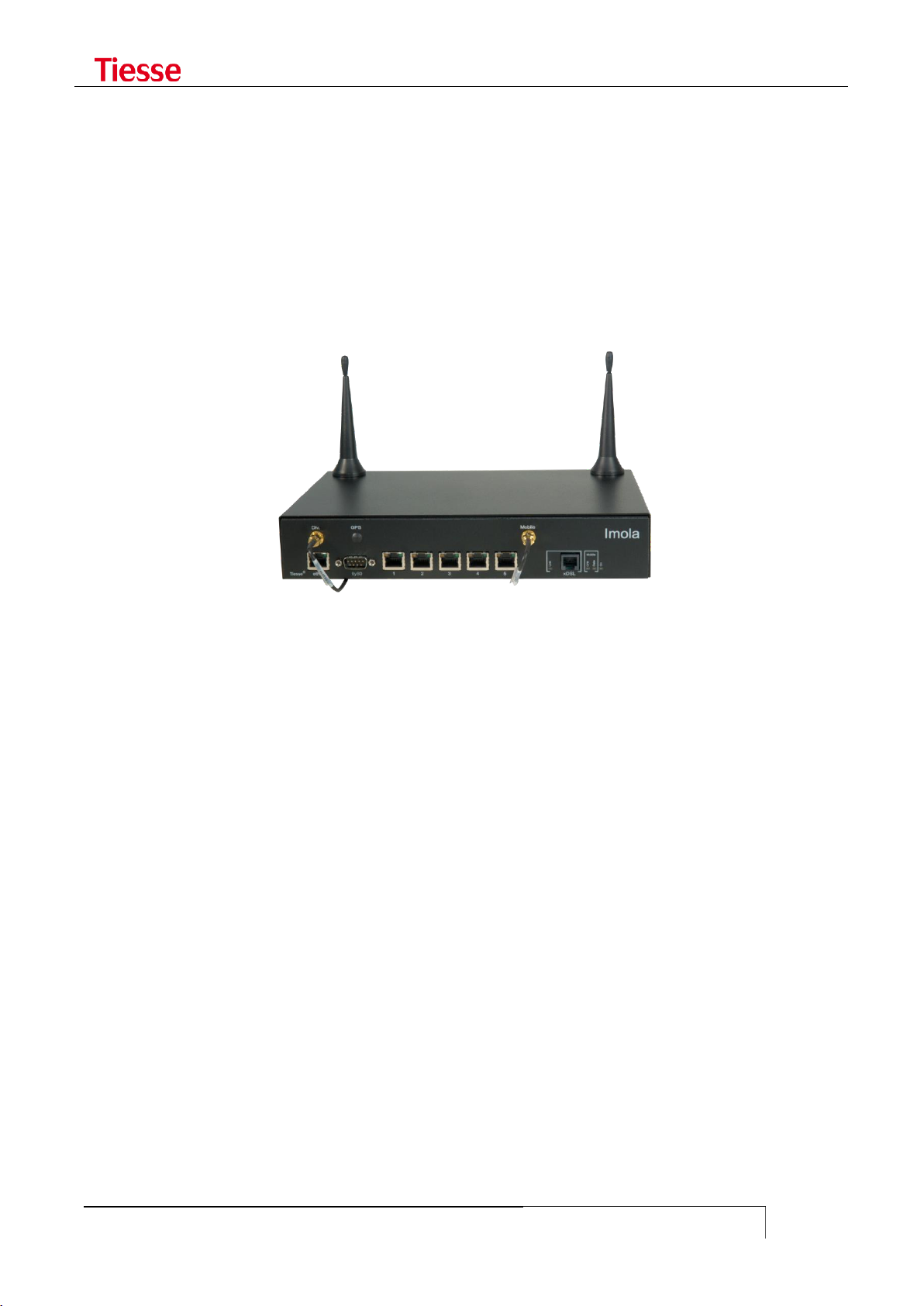
Figure 1: IMOLA Mod. 5262
IMOLA is based on 3 functional modules, not necessarily physically separate: a module containing
the main features; a module hosting protocol controllers and WAN interface; a power supply
module which may supply both an AC/DC converter (Internal Power Supply) and a DC/DC converter
(External Power Supply).
The main characteristics are:
Network Processor
64-256 MB RAM, depending on the model
512KB Boot Flash
16-256 MB Flash Memory for OS and applications, depending on the model
It also contains the following communication ports:
1 FE or GBR Ethernet (except for LX models, where there will be only one port FE). The GBE
port can optionally have a connector SFP
1 console port RS232 with DB9 male connector
1 ISDN S/T BRI with RJ 45 connector (only in some models)
1 integrated switch LAN up to 8 FE/GbE ports with VLAN 802.1q support (optional)
1 Wi-Fi port 802.11 b/g/n (optional)
1 ADSL/ADSL2+ with RJ11 connector (optional)
1 GSM/GPRS/EDGE/UMTS/HSDPA/HSUPA port (optional)
1 GSM/GPRS/EDGE/UMTS/HSDPA/HSUPA/LTE port (optional)
1 synchronous serial port with LFH 60 V.35 connector (optional)

Introduction
USER GUIDE
15
X
0
No mobile network connection
1
GPRS (models no longer in production)
2
GPRS / EDGE
3
GPRS / EDGE / UMTS / HSDPA
4
GPRS / EDGE / UMTS / HSDPA / HSUPA
5
GPRS / EDGE / UMTS / HSDPA / HSUPA / LTE
Y
0
1 Ethernet port present
1
2 Ethernet ports
2
5 switch Ethernet ports (4 ports in LX version)
3
1 Wi-Fi (besides Ethernet switch)
8
8 Ethernet ports1
Z
0
No WAN connection
1
ADSL
2
ADSL2+
3
HDSL
4
SHDSL
6
VDSL2
K
0
Ethernet ports FE 10/100 Mbps
2
Ethernet ports GBE 10/100/1000 Mbps
1
2 G.SHDSL ports that can be used in 2-Wire o 4-Wire mode
2 RS232 DCE ports with DB9F connector and/or DB25F (optional)
2 SFP optic port (optional)
4 ISDN BRI VoIP ports (optional)
4 FXS VoIP and 1 FXO port (optional)
In order to distinguish the different characteristics and communication interfaces, each model is
identified by the name Imola XYZK, where:
X identifies the type of WAN connection on mobile network
Y identifies the type of local network connection
Z identifies the type of WAN connection
K identifies the type of LAN port (FE or GBE)
The values are as follows:
Additional expansion cards can be mounted to provide:
asynchronous RS232 serial connectivity through two DB9 ports or a DB9 and a DB25 port,
both for connecting serial devices such as RTU, CBT, SCADA and various controllers (IKR)
direct connectivity on Fiber Optic via two SFP ports
- In the model with 8 Ethernet ports, the 6, 7 and 8 are always FE independently of the other 5, which may be the FE or GBE

Introduction
USER GUIDE
16
V.35 connection interface (IKH)
Wi-Fi connectivity (IKW)
For example:
the model 5200-IKR-IK2F has:
o LTE interface
o 1 FE port
o 5 FE switched/router port s
o 2 RS232 ports
o 2 SFP Fiber Optic port
The model 5262-IKH has:
o LTE interface
o 1 Gigabit Ethernet port
o 5 Gigabit Ethernet switched/routed ports
o 1 A/VDSL2 port
o 1 V.35 port
The model 5262-IKS has:
o LTE interface
o 1 Gigabit Ethernet port
o 5 Gigabit Ethernet switched/routed ports
o 1 A/VDSL2 port
o 1 G.SHDSL port
The model 5262-IKW has:
o LTE interface
o 1 Gigabit Ethernet port
o 5 Gigabit Ethernet switched/routed ports
o 1 A/VDSL2 port
o 1 b/g/n Wifi
These cards are called, respectively, IKR and IK2F and these become the suffix of the name of the
router.
Some models are also available with external power supply and called Imola LX. In this model the
ISDN BRI port is not present and the switch has 4 Fast Ethernet ports instead of 5. In other cases in
order to identify the generic model the name Imola Full is used.
It is possible to provide a DC/DC 9-36V supply power: in this case the router is called ImolaT.
LED general meaning
USER GUIDE
17
LED type
LED
COLOR
BEHAVIOUR
DESCRIPTION
Router On / Off
On
Green
On
The router is powered on
Ethernet interface
(2 LEDs integrated in
the connector)
Left
Yellow
Off
The interface is damage or the connection
is running at 10Mbps
On
The Ethernet interface is connected at
100Mbps
Right
Green
Blinking
LAN activity
ADSL/VDSL interface
(1 LED)
Imola XX20
Link
Green
Blinking slowly
Shows that the interface is ready to
establish a connection
Blinking fast
Shows that the communication with the
central has been established and the
connection is ongoing
On fixed
Connection established
ADSL interface
(3 LEDs)
Imola XX10
PW / ON
Green
On
ADSL internal modem correctly powered.
Link
Green
Blinking
Shows the sync phase with the central
On
Shows that the synch phase has been
successful
Data
Green
Blinking
Data traffic
ISDN interface
(2 LEDs integrated in
the connector)
Left
Yellow
On
Physical ISDN level is active (ongoing call)
Right
Green
On
Shows that at least one ISDN session is
active.
Note: while the system is booting, both LEDs are on. They turn off when the booting phase is finished.
Interface GPRS
(modem GPRS or EDGE
- models 1xx0 e 2xx0)
Link
Green
Blinking fast
Shows the sync phase with the central
Blinking slowly
1-2 seconds on: the connection has been
correctly established
On
GSM connection is active
Data
Green
On
GPRS connection is active and the
interface has obtained an IP address
Interface GPRS
(modem HSDPA or
UMTS - models 3xx0)
Link
Green
On
The connection is correctly established
Data
Green
On
GPRS connection is active and the
interface has obtained an IP address
HDSL interface
V35
Green
On
The router has detected the network
SHDSL interface
Link
Green
On
The SHDSL modem is correctly powered
and initialized
Data
Green
Blinking
Shows the sync phase with the central
Steady on
The sync phase was successful
LED GENERAL MEANING
Different LED indicators show the status of connection. The position of the LEDs and the related
labels can be different according to the various models.

LED general meaning
USER GUIDE
18
LED type
LED
COLOR
BEHAVIOUR
DESCRIPTION
Router On / Off
On
Green
Fixed on
Imola is on
Ethernet interface
Eth1 -1
Green
Fixed on
The connection is active
Eth1 -2
Eth1 -3
Eth1 -4
FE interface
FE
Green
Fixed on
The connection is active
GbE interface
GbE
Green
Fixed on
The connection is active
Wi-Fi interface
Wi-Fi
Green
Fixed on
The connection is active
xDSL interface
xDSL
Green
Slow Blinking
1sec. on / 1sec. off
Activating: the modem is waiting
for the connection
Fast Blinking
0.500 ms on
0.500 ms off
Handshaking
Fixed on
The connection is active
Mobile interface
4G/3G
Green
Fixed on
The port is configured via CLLI
and it is usable
Slow blink 1s on 5s off
Not active or searching for the
connection
Fast blink 0.5s on /
0.5s off
The connection is active
GSM
Off
No connection
Fixed on
The connection is active
ISDN interface
Link
Green
Fixed on
Physical ISDN level is active
(ongoing call)
AcT
Fixed on
Shows that at least one ISDN
session is active.
Imola 5260's LED

LED general meaning
USER GUIDE
19
FUNCTIONALITIES
Other functions may be associated to the communication services:
ACLs support
Authentication and accounting support via RADIUS
AAA support via Tacacs+
NAT/PAT functions
Stateful Firewalling functions
VRF-Lite support
VPN with IPSec 3DES Encryption
Tunnel GRE
L2TPv2 tunnel
L2TPv3 tunnel both static and dynamic
PPTP Tunneling
Open VPN Tunneling
Easy VPN Tunneling
Advanced Routing (Policy routing)
RIP, OSPF, BGP routing and BFD support
PIM protocol support (Protocol Independent Multicast) in Dense mode, Sparse mode and
Source Specific Multicast
IGMP Proxy and IGMP Snooping support
Band Optimization with QoS (Quality of Service)
VRRP support (Virtual Router Redundant Protocol)
Functions of IP SLA with Responder Time Reporter
SNMP v1/v2/v3
TR-069 support
Client and Server DHCP
Local and remote logging
Client and Server Telnet and SSH
Administration and control tools (ping, traceroute, debug ip packet, …)
The Command Line Interface (CLI), owned by Tiesse S.p.A., allows the configuration and
management of the system in a simple and guided way.
LED general meaning
USER GUIDE
20
X
1
GPRS
2
GPRS / EDGE
3
GPRS / EDGE / UMTS / HSDPA
4
GPRS / EDGE / UMTS / HSDPA / HSUPA
5
GPRS / EDGE / UMTS / HSDPA / HSUPA / LTE
Y
0
1 Ethernet FE 10/100 Mbps port
1
2 Ethernet FE 10/100 Mbps port
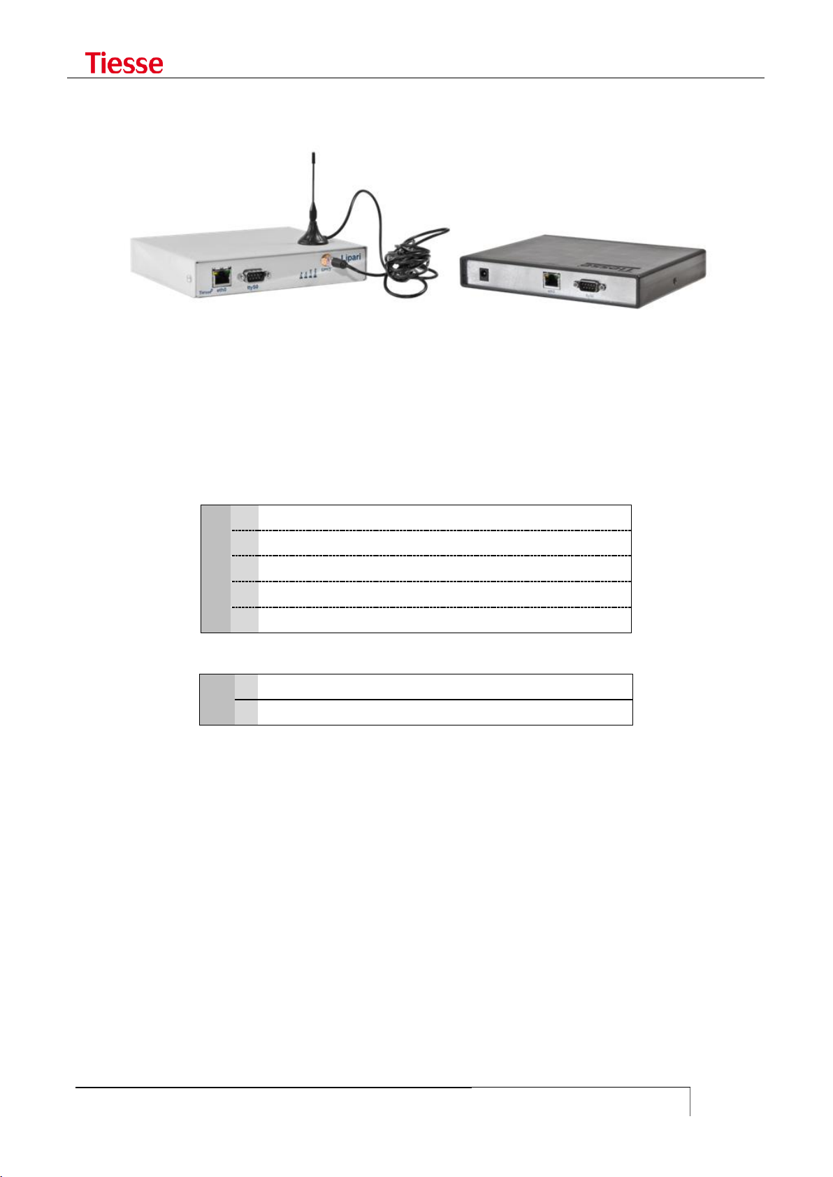
LIPARI MODELS
Lipari is another Tiesse‟s router model, which has equivalent functions to the routers of the Imola
series, but it only supports mobile connections. In the picture above you see two models of the
Lipari series.
It has a module of external power supply AC/DC 5Vdc / 1A.
As in the Imola models, in order to distinguish the different features and communication interfaces
each model is identified by the label Lipari XY00 where:
X identifies the type of WAN connection on mobile network present.
Y identifies the number of LAN Ethernet ports 10/100.
LED general meaning
USER GUIDE
21
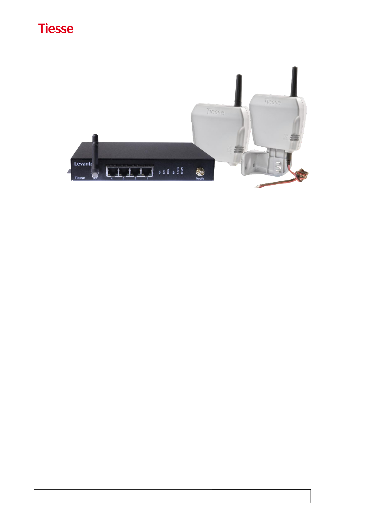
LEVANTO MODELS
Levanto models are functionally equivalent to Lipari‟s, the difference is about the RS232 ports that
Levanto have, which are used to connect serial devices like RTU, SCADA, etc.
Levanto 410 has a 3G port, a Ethernet port and a DB9 DCE serial port; in the factory configuration,
the serial port is used as console.
Levanto 441 has a 4G port, a Ethernet port and four RJ45 serial ports; it is equipped with an
external power supply AC/DC 5VDC/1A type. The serial port 1 (the first on the right) is used as
console while the others (2 – 3 and 4) are used to do the conversion from serial to TCP/IP.

LED general meaning
USER GUIDE
22
IMOLA E
Imola E system addresses the need to integrate the data and voice routing functionalities, both
wired and mobile, in a device that must be modular, configurable and highly reliable, even in
industrial environment which are subject to electromagnetic perturbation.
Imola E offers ina a single modular system the maximum integration between different
communication channels: copper and fiber optic Ethernet, ISDN BRI, serial WAN V.35 and E1, 3G /
4G, ADSL, G.SHDSL, interface to PSTN analog phones for voice routing with IP protocols on local and
geographic networks.
The modular architecture allows its evolution over time, integrating new functionalities and new
communication channels on a already consalidated system.
The automatic backup over ISDN or over radiomobile network (or any other secondary channel, like
satellite for example) and the presence of redundant power supplies ensure the continuity of
operation.
We particularly care about the immunity from electromagnetic perturbation, environment conditions
and safety reuglations.
Imola E is an evolution of the products of the serie Imola, it is the Tiesse Network Open Appliance,
based on RISC Network Processor and Linux platform, optimizes for networking.
Imola products are used as core components to produce LAN/WAN connectivity solutions where
security and integration of multiple ambient, protocols and transmitting channels are crucial.
The products in the Imola serie provides hardware/software functional blocks including router,
firewall, VPN server, LAN and WAN interfaces, asynchronous serial lines for terminal connections,
ISDN interfaces, ADSL2+, LTE/HSDPA/EDGE/GPRS, VoIP functionality, automatic backup channels for
the continuity of the service.
Depending on application requirements, it is also possible to evolve the product by introducing new
features through remote software upgrades, thus preserving investment and reducing operating
costs.
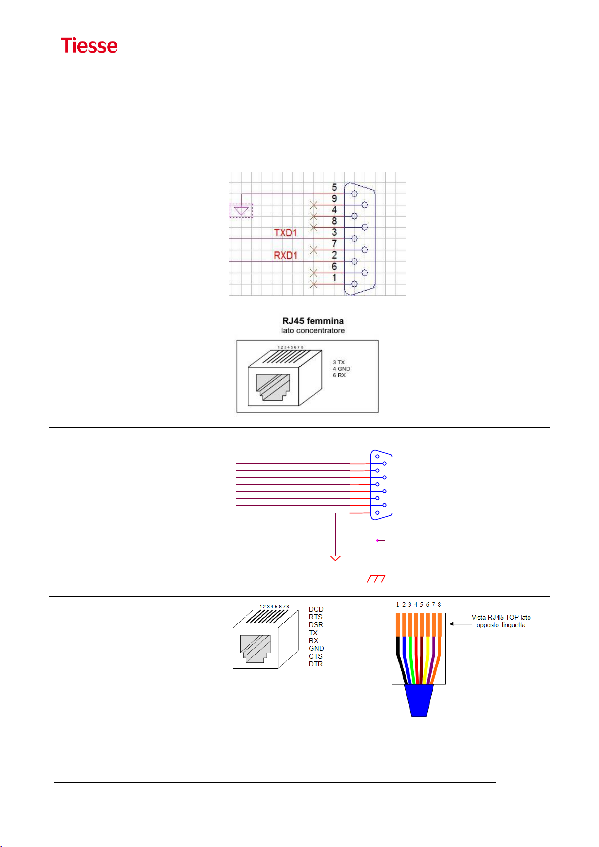
LED general meaning
USER GUIDE
23
Imola / Lipari
DB9 male connector
Imola
RJ45 connector
Levanto 310/410
DB9 female connector
Levanto 441
RJ45 connector
COM_DSR
COM_RTS
COM_CTS
COM_RI
GND 5 9
4 8 3
7
2
6
1
10
11
P1
DB9F SH
COM_DCD
COM_RXD
COM_TXD
COM_DTR
SERIAL CONNECTORS
To access the router you can use the console port, which can be different from model to model.
Below you find a scheme for the different kind of console port.

Accessing IMOLA
USER GUIDE
24
2
ACCESSING IMOLA
Access can be made via the console port with DB9 male connector on the front of Imola, with a
proper null modem cable, using any program of terminal emulation (HyperTerminal, Minicom,
Putty, ...) or via a Telnet connection to one of the IP addresses present on Imola.
Imola LX models have only a 4 ports integrated switch, each numbered 1 to 4. The factory
configuration, all the ports refers to a single IP address on the logical interface eth0.
The other models have a single Fast Ethernet port identified by the label eth0 and a 5 ports
integrated switch (8 in some models), where the ports are numbered 1 to 5 (or 8). In the factory
configuration all the switch ports refers to a single IP address and the logic interface is named eth1.
In case of direct connection to the single Ethernet port of Imola Full model (eth0 port) a LAN cross
cable should be used. Thanks to the auto-mdx function any kind of cable may be used in case of
connection to any port of the integrated switch.
Tiesse spa - IMOLA Interworking Unit
No Radius configured. Using Local authentication
login: root
Password:
local: Authentication OK
Service Type is: Administrative-User
Idle timeout is set to 3600 seconds
Connected Users:
ttyp1 root
You are logged on ttyp1
The configuration environment presents this prompt: username@hostname where username is the
login and hostname is the configurable name of the system. The service type (Administrative-User
or Login-User) indicates the user‟s privileges, the session inactivity timeout, the users connected
and the virtual tty used.
You can modify the timeout session by using:
idle <seconds>
where 0 means infinite.
This list can be checked any time through who command2:
root@Imola> who
Connected Users:
ttyp1 root
ttyp2 root
You are logged on ttyp2
root@Imola>
- Even though several users can be connected to the router, it is advisable that only one user modifies the configuration in
order to avoid undesirable effects.

Accessing IMOLA
USER GUIDE
25
SOFTWARE VERSION AND MODEL
It is possible to read the router‟s model through the command show model:
root@IMOLA> show model
Tiesse Imola 5262 Multiprotocol Router
The command show version shows the software‟s version.
root@IMOLA> show version
Imola version: 5.4.3-2
The version number adopts the naming convention: 5.x.y-N
The first number identifies the hardware platform used in the production.
The value of x indicates the major number, which changes in case of relevant functionality.
For example, with the support of protocol IPv6 it is possible to pass from release 4.3.1 to
release 4.4.0.
The value of y indicates the minor number, which increases when other independent
functionality, which do not affect other software‟s functions, are added. For example, with
the addition of the Tacacs support it is possible to pass from release 4.3.0 to release 4.3.1.
The suffix N indicates the build number. It increases in case of small bug-fixing which do
not require non-regression tests. For example, by making a correction in the module
managing IP SLA‟s functions it is possible to pass from release 4.3.1-0 to 4.3.1-1.
In addition to the router with version 5.x.y-N, we produced router whose version is 1.x.y-N type,
router with versions 2.xy-N type and 4.x.y-N version. There is no difference from a functional point
of view.
ACCESS VIA TTYS0 PORT
Cable Type: null-modem DB9
IMOLA Port: ttyS0 port
Application: Windows HyperTerminal (or similar)
ttyS0 port settings
Some models have the console with a RJ45 connector instead of DB9. The settings are the same.
When using the ttyS0 port to access Imola, the system used for the connection has to be configured
in the following manner:
Bits per second: 9600
Data bits: 8
Parity: none
Stop bit(s): 1
Flow Control: N.A. (Not Applicable)
Accessing IMOLA
USER GUIDE
26
eth0 port
eth1 port
IP Address
10.10.113.1
172.151.113.1
Netmask
255.255.0.0
255.255.0.0
Broadcast
10.10.255.255
172.151.255.255
Network Address
10.10.0.0
172.151.0.0
The following figure shows an example:
Tiesse spa - IMOLA Interworking Unit
login: root
Password: *********
Imola# cli
Service Type is: Administrative-User
Idle timeout is set to 600 seconds
Connected Users:
ttyS0 root
You are logged on ttyp1
ACCESS VIA ETH0 AND ETH1 PORTS
Cable Type: LAN (Ethernet type)
IMOLA Port: eth0 or eth1 port
Application: Telnet (or similar)
eth0/eth1 default settings
In models with a LAN integrated switch (IMOLA X2X0); the connection to eth1 port can be made via
any of the available ports in the switch.
USERNAME AND PASSWORD
In order to access Imola login and password need to be specified.
Factory configuration accepts the following login and associated password:
login: root
password: tiesseadm
It is possible to change the root user password thanks to the CLI command:
which in interaction modality asks to introduce the new password.
Further users can be added using the command:
change_password root
add_user <user_name>

Accessing IMOLA
USER GUIDE
27
which asks to specify the associated password too.
The command
set user <username> password <password>
allows you to create a user in non-interactive mode.
Users added through the add_user command are Login users, as well as the ones added via set
user command. The su command gives the possibility to pass from Login mode to Administrative
one. For example:
There are two types of users: Administrative-User and Login-User.
Administrative-User can execute any kind of CLI command, while Login users may only execute
a limited number of these commands, for example commands which modify the configuration are
not allowed, while the ones about displaying are allowed.
Tiesse spa - IMOLA Interworking Unit
No Radius configured. Using Local authentication
login: mario
Password:
local: Authentication OK
Service Type is: Login-User
Idle timeout is set to 3600 seconds
Connected Users:
ttyp0 mario
You are logged on ttyp0
mario@Imola# set hostname MyRouter
Command "set hostname MyRouter ..." not allowed for this user
mario@Imola# su root
Password:
root@Imola> set hostname MyRouter
Setting hostname to MyRouter
root@Imola> quit
mario@Imola#
mario@Imola# set eth1 ipaddr 3.3.3.3
Command "set eth1 ipaddr 3.3.3.3..." not allowed for this user
mario@Imola#
For example, if you access the router using the user "mario" and you try to run the command set
hostname in order to change the name of the router, the command fails due to the lack of the user
privileges. Using the su command and specifying the correct password it is possible to enter
Administrative mode with more privileges. The hostname can now be changed.
The quit command allows to go back to the previous user.
Pay attention to the last character of the prompt: the character # for Login User and the character >
for Administrative User.
The authentication mode may be configured via RADIUS protocol as described in the relative
chapter. In this case the RADIUS server determines which users have full rights and which users
have restrictions.

Accessing IMOLA
USER GUIDE
28
To view the list of the local users and their respective privileges (granted or revoked), you can use:
show user
GRANTING AND REVOKING PRIVILEGES
An Administrative User may give Login Users the possibility to execute certain commands generally
not allowed. In the same way, the Administrative User may revoke to an Administrative the
possibility to execute commands which are normally allowed.
grant-to <username> <command prefix>
executed by an Administrative User gives the user <username> (Login User), the possibility to
execute commands which begin with the specified prefix.
revoke-to <username> <command prefix>
executed by an Administrative User forbids the user <username> (Login User)) the possibility of
executing commands beginning with the specified prefix.
For example, the users "operator" and "technician" are respectively Login-User and AdministrativeUser. "Operator" can normally check the configuration but cannot change it, while "technician" can
make any modification without restrictions. The commands:
grant-to operator set eth1
revoke-to technician set isdn dialer ippp1
allow "operator" to configure the Ethernet port and denies "technician" the right to configure the
ISDN dialer.
In order to eliminate a privilege or a revocation the following commands are used:
no-grant-to <username> <command prefix>
no-revoke-to <username> <command prefix>
The <command prefix> string is the initial part of any configuration command.
It is necessary to pay attention when only one Administrative User exists, for example root. The
commands:
revoke-to root set
revoke-to root no-revoke
definitively deny root the right to execute any kind of configuration command.
PRIVILEGE LEVELS AND ENABLE COMMAND
Besides Administrative and Login users, when the access to the router is governed by a Tacacs+ (or
RADIUS) server, it is possible to manage different levels of privilege in order to establish which
commands may be executed.
It is possible to establish up to 15 levels of privilege, numbered from 1 to 4. The higher the level,
the more the available commands. It also exists the 15 level which corresponds to a condition of
superuser, i.e. a user without any kind of restriction on commands (similar to Administrative
user described in the previous section).

Accessing IMOLA
USER GUIDE
29
The level of privilege is established by the Authentication server used (RADIUS or Tacacs+). In the
first case it is necessary to configure a Custom attribute in the server (described in the RADIUS
section).
In the fault configuration there are 3 levels:
Level 0. The available commands are enable, exit and quit
Level 1. The available commands are those related to a Login user, that is only reading
commands without possibility of modifying the configuration
Level 15. The available commands are those related to an Administrative user. This means
that (potentially) all the commands are available.
The N level has all the privileges of lower levels, in order to pass from a level to another it is
necessary to know the password associated to that level.
The command:
set privilege level N <command prefix>
if executed by an authorized user, establishes that at N level all the commands starting with the
specified prefix can be executed. For example, by using:
set privilege level 3 set adsl
it is specified that users which have received a 3 level of privilege, can execute all the configuration
commands of the ADSL interface.
In order to eliminate the privileges previously set the command is:
set no-privilege level N <command prefix>
In order to check the current level of privilege the command is:
show privilege
In order to pass from a lower to a higher level a password should be associated with the higher
level.
The command which allows to associate the password with a certain level is:
set enable password level N
In an interactive modality it asks to enter the password. In order to eliminate the password the
command is:
set no-enable password level N
By this way the N level becomes inaccessible from lower levels.
In order to access a higher level the command is:
enable N
It asks to enter the password associated with the N level. If the password is correctly set, the user
can use all the commands associated with the N level.
For example, if a superuser has set the following commands in the router:
set privilege level 3 set eth1
set privilege level 3 set gprs
set enable password level 3

Accessing IMOLA
USER GUIDE
30
it is possible to grant a user with level of privilege 3 to configure the Ethernet and the mobile ports,
and a password has been associated with this level too.
The command used to set the password is interactive and it is here represented:
admin@IMOLA> set enable password level 3
16Changing password for $enable3$
New password: ********
Retype password: ********
Password for $enable3$ changed by root
In an Authentication server, Tacacs or RADIUS, a user named poor with the level of privilege 1 has
been configured. A connection to the router is made and the authentication occurs through the
poor user:
telnet 10.10.113.1
Trying 10.10.113.1...
Connected to 10.10.113.1.
Escape character is '^]'.
--------------------------------------------------------------
(IMOLA) (port 0)
--------------------------------------------------------------
login: poor
Password:
TACACS+: Authentication OK
Service Type is: Login-User
Privilege Level is: 1
Idle timeout is set to 3600 seconds
Connected Users:
pts/0 poor@IMOLA
You are logged on pts/0
poor@IMOLA#
A command to configure the IP address of the Ethernet interface is executed:
poor@IMOLA# set eth1 ipaddr 192.168.1.1
% Command "set eth1 ipaddr 192.168.1.1" not allowed for this user
poor@IMOLA#
The command fails. Another command is executed in order to access a higher level:
poor@IMOLA# enable 3
Password: ********
$enable3$@IMOLA#
$enable3$@IMOLA# show privilege
Current privilege level is 3
$enable3$@IMOLA#
At this point the command:
$enable3$@IMOLA# set eth1 ipaddr 192.168.1.1
 Loading...