


version:4.6.23
UP mini
user manual

Table of Content
Precautions
..........................................................................................................................
01
Printer Body illustration
..................................................................................................
03
Accessories
..........................................................................................................................
05
Installing the Print Head
................................................................................................
06
Install the Perf Board
.......................................................................................................
07
Install UP Software
...........................................................................................................
08
Initialization of Printer
.....................................................................................................
09
Platform Calibrate
1.Setting Nozzle Height
......................................................................................
11
2.Setting Compensation Values
......................................................................
13
Prepare for Printing
..........................................................................................................
14
Loading a Model
.................................................................................................................
15
Software Interface
.............................................................................................................
17
Moving Model
......................................................................................................................
18
Rotate Model
.......................................................................................................................
19
Scale Model
..........................................................................................................................
19
Duplicate Model
..................................................................................................................
20
Printing Parameters
.........................................................................................................
20
Annotation for Printing Parameters
..........................................................................
21
Repair Model
........................................................................................................................
22
Calibration for the Correct Dimension
.....................................................................
23
Printing Techniques
.................................................................................................
24
Troubleshooting
..................................................................................................................
25

01
1. UP mini 3D printer requires power adapter provided by original manufacturer. Otherwise it
could casue damage to machine or even fire hardzard. Please also keep the power adapter
away from water and high temperature.
2. During printing, the nozzle of the printer will reach 260oC and the print platform could reach
60oC. Please do not touch these parts with bare hand while they are hot, not even with the heat
resistant gloves included with machine as the temperature could damage the glove and your
hand.
4. During Printing, the nozzle and print platform will move at high speed, do not touch these parts
while they are moving.
5. Please wear goggles when removing the supporting material from model and detaching model
from perf board.
6. When printing ABS and PLA, slight smell will be produced, please run the printer in a well
ventilated environment. We also suggest you
to
put the printer in an enviroment with stable
temperature, as unwanted cooling could has adverse eect on print quality.
7. When UP softwre is sending data to printer, where the status bar on the left bottom corner
is showing "sending layers", do not unplug USB cable, as this will interrup data transfer and
results in printing failure. USB cable can be unpluged after data printing started.
8. UP mini's working temperature is between15
o
C and 30oC relative humidity 20%-50%. It is
recommended to discharge static charge from user's body before touching the machine to
prevent interruption of printing and damaging the printer.
Warning label on printer:
High Temperature, do not touch!
Warning label on printer:
Moving parts, do not touch!
Precautions

02
UP mini Specication
Technology MEM (Melted Extrusion Manufacturing)
Build Volume 120x120x120mm
Print Head Single, Modular for easy replacement.
Z-resoution 0.2/0.25/0.3/0.35mm
Supporting Structure Automactically generated, easy to remove,
adjustable
Platform Leveling Manual
Print Surface Heated bed with perf board
Unterthered Printing Yes
Bundled Software UP Software
Compatible File Formats STL, UP3, UPP
Connectivity USB
Operating System WinXP/Vista/7/8, Mac OS
Poweradapter 110-240VAC, 50-60Hz, 220W
Printer Body Metal Chassis, enlosed.
Printer Weight 6KG / 13 LB
Printer Demiension 240(W) x 355 (H) x 240 (D)mm
Weight with Packaging 11.2KG / 25LB
Printing
Software
Power Supply
Mechanical

03
USB Port
Power Connector
Top Lid
Front Door
Initialization Button
Power Switch
Spool Holder
USB Port
Power Connector
Printer Body illustration

04
Print Head
Print Platform
Initialization Button
Print Head
Nozzle
X-Axis
Y-Axis
Z-Aixs

05
Accessories
Print HeadSpool Holder ABS Filament
Plier
*If anything is missing please contact your local distributor or
support@pp3dp.com
Perf BoardUSB Cable
Power Adapter
Filament guiding tube
Hex Key
Gloves
Nozzle Wrench
Blots and Nuts
Shovel

06
Installing the Print Head
Correct installation.
Incorrect installation, note the magnet
under the print head is not in contact
with the motor.
There are 3
magnets for holding
the print head in
place.
1
During installation
make sure the
magnets are aligned
to the metal plates
on the print head's
stepper motor.
2
After tting the print
head, plug in the
cable to connector
residing on the print
head.
3

07
Slide the perf
board into the
slots on the
2 sides of the
platform.
Finsihed.
Install the Perf Board
Install the Spool Holder
Hook the spool holder on the back of the printer.
Install Filament Spool
As shown in the diagram, put the
lament spool on the spool holder
and put the lament through the
filament guide tube, then insert
the tube into the printer through
the hole under the lid.
1 2
08
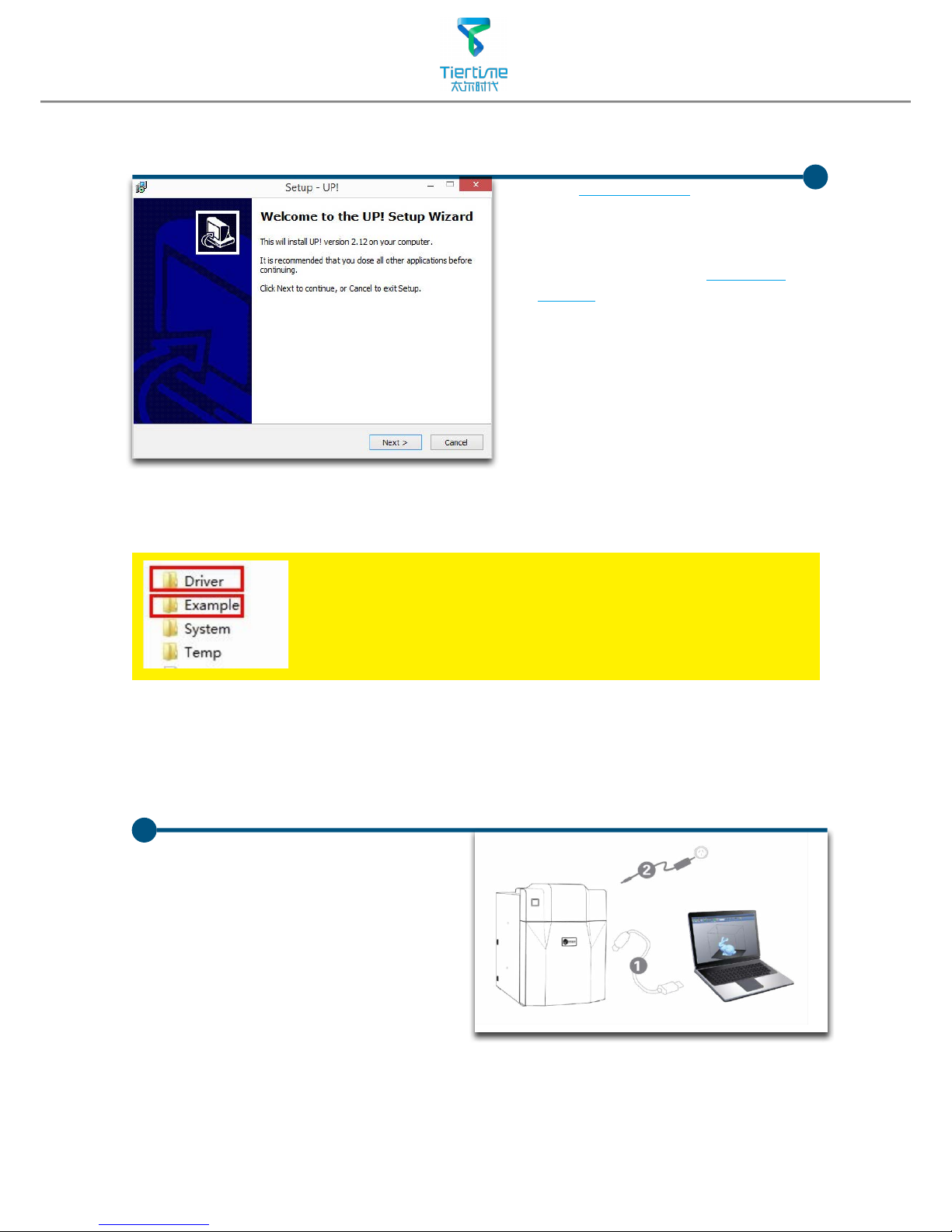
Install UP software
1. Go to
www.pp3dp.com
to download
the latest version of UP Software.
2. Double click UP! Setup.exe
to install the software(default
installation directory
C:\Program
files\UP
a pop up window will
appear, select"install" and
following the instruction to
finish. The printer's driver is now
installed into the system.
After installation,in the UP folder:
Driver folder contains the printer drivers.
Example the example folder contains STL les for the printed
parts of UP printers and example les.
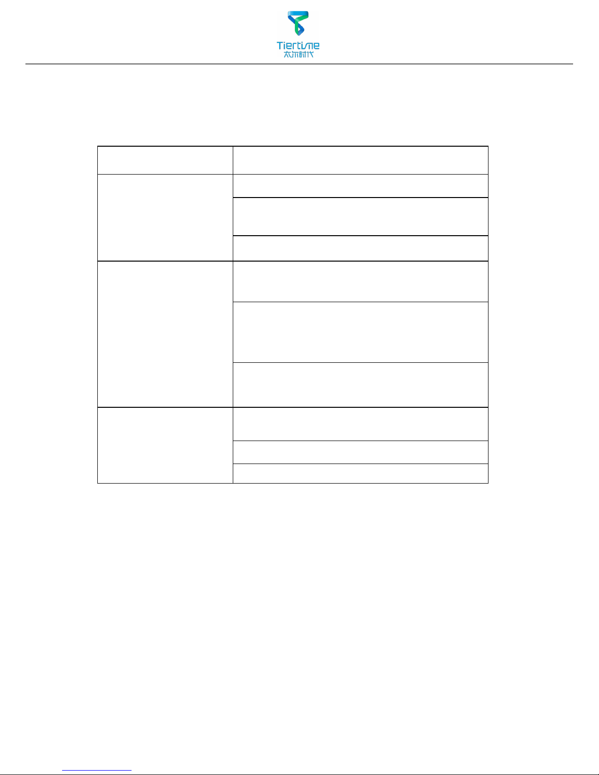
Testing of printer driver installation
UP
UP
First make sure computer and printer
is connected to computer via USB
cable and the printer is switched on.
The initialization button should be light
up in red color.

09
After driver installation,
double click the desktop
icon of UP software to
open it.
UP
Click"3D Print".
"Initialize" and "Maintenance"
options will light up and
avaliable for selection.This
indicate the successful
installation of printer driver.
Initialization of printer
Initialization is required for everytime the machine is switched on. During initialization the
XYZ aixs will move slowly and hit the endstops. This is essential as the printer need to nd
the endpoints of each axis.
Initialization Button
Two ways of initialization:
1. UP mini can be initialized by clicking initialization option in
the menu which is shown above.
2. The printer has initialization button on front of the
machine shown in the picture below. When the printer is
idle, press this button will trigger initialization
After initialization, the other software options will light up
and become available for use. These options can only be
chosen after initialization.

10
The other functions of Initialization Button:
1. Stop current print job:During printing press and hold the button.
2. Switch On/Off print head LED:Quick double hit of the button.
Platform Calibration
Plarform calibrate is the most important step for successfull printing, as it ensures the first
layer adhesion.The actaual calibration is done by measuring the distance between the nozzle
and platform.Ideally, the distance between nozzle and platform is constant, but in reality the
distance varies at dierent position due to many reasons (eg. slightly tilted platform.) To calibrate
the platform, we just need to tell the machine, on 9 calibration points, the height of plaform
that is touching the nozzle.The printer will able to compensate for distal errors base on our
measurements.The calibration procedure contains 2 parts:
1. Setting nozzle height.
2. Setting compensation values.
D. 9 calibration point buttons,
represent 9 positions on platform,
after clicking the nozzle will move
to the corresponding positions.
The drop down menu beside
the button is for setting leveling
compensation values.
Platform calibration interface:
Open: Menu - 3D Print - Platform calibrate
Interface annotation:
A. Moving Platform UP/DOWN:
click/hold the button, platform
will move accordingly.
B. Display the current platform
height.
C. Setting nozzle height: click this
will set the current platform
height as the nozzle height.

11
Platform Calibrate: 1.Setting Nozzle Height
Setting nozzle height, actually, is not setting the nozzle itself as UP mini's print head
does not move in the Z-axis. Here the nozzle height we are refering to is a platform height
value, at this height, the platform will be just touching the nozzle (thus "nozzle height").
After setting the value, the platform will be restricted to move over "nozzle height" as the
it will start crashing onto the nozzle if going beyond it. The nozzle height value is important
for protecting the printer from damages as well as being the basis for calculating leveling
compensations.
During the calibration we are measuring distance shorter than 1mm, so we recommend
using a print paper as a guide for measurement.
Protocol for setting nozzle height:
1
2
3
4
5
Initialize printer
Open the calibration interface
and press the UP key, note
the current height value, stop
the platform at about 115.
Put print paper on platform.
Hit the "5" button.Nozzle will go
to the center of the platform.
Raise the platform until it is
just touching the nozzle. We
can move the paper between
the nozzle and platform and
see if there is any resistance.
Like to diagram below.

12
Platform Too high, nozzle
is pinning paper onto
the platform, Lower the
platfrom slightly.
Just right,could feel some
resistance when moving
the paper.
Platform too low, no
resistance at all when
moving paper, raise the
platform slightly.
When obtained the right platform
height, write down the value of "current
height".
We will refer this as the "platform
height".
Repeat step 1- 6 for all other 8
positions and obtain their platform height
value when touching the nozzle.
6
7
8
When obtained the platform value of
all 9 positions.Find out the smallest value
among the 9 calibration points.
As you can see in this case, the
calibration point 1 has the smallest
platform height value, it is actully the
highest point on the platform. (therefore
the platform does not need to rise as
high as the other points to reach the
nozzle
Platform Values at 9 calibration points
(hypothetical):
1: 119 2:119.5 3: 120
4: 119.5 5: 119.9 6: 119.1
7: 119.2 8: 119.4 9: 119.8
We set this height as "Nozzle Height"
since it is where the nozzle first start to
touch the platform. Now go to calibration
point 1 and rise platform to 119.
Click the button" Set Nozzle Height" to
nish.

13
Platform Calibration: 2.Setting Compensation Values
As shown in the left, when platform
is at the "nozzle height", only part of
the platform is touching the nozzle.
Therefore we need to set compensation
values for all other calibration points to
inform the printer about the distance
between nozzle and print surface
thorughout the XY plane.
For example, setting the
compensation value for calibration
point No.3. Assume the "platform
height" is 120 and the "nozzle height"
is 119, the compensation value
should be set to 1.0.
After setting 1.0 in the drop down
menu, the nozzle will move to point
No.3 and the platform will rise 1 mm.
Now we can use the paper again to
verify the compensation value.
After setting all calibration points click
“Appy/Save Current Values ” to finish
the calibration.
Afte setting the nozzle height, the drop down menu next to the
buttons will be available. A compensation value between 0.1 - 1.0 mm
will be available for setting.
To calculate compensation value:
Platform height - nozzle height = compensation value

14
Prepare for Printing
Make sure printer switched on and
connected to computer. Select Main
Menu - 3D Print - Maintainance.
Hit "Extrude" button,the print
head will start to heat up, within 5
minutes its temperature will reach
260
o
C,then printer will buzz and the
print head startts to extrude.
Gently insert the iament into the
small hole on the print head. The
filament will be feed into the print
head automatically when it reach the
extruder gear inside the print head.
Check the nozzle for plastic
extrusion. If plastic is coming out
from the nozzle that means the print
head is ready. The extrusion will stop
automatically.
1
2
3
4

15
Click Load
Choose your model.
Loaded model on
the print plate.
Loading a model
1
2
3
4
Click print to open
the print preview
window.

16
Click "OK" to start printing.
The program will rst slice
the model into Gcode and
then transfer the data to
the printer.
Annotation of Print Preview Interface
:
After sending the data, the
program will suggest the amount
of material and time needed for
the model in a pop up window.
At the same time, the nozzle
will start to heat up. The print
job will start automatically after
clicking"OK"
When printier nished receiving the print data, user could disconnect
it from computer for untethered printing.
a
b
def
h
g
c
5
6
a. Display the printer model.
b. Dispaly the noozle height.
c. Click to enter printer preference to set printing parameters.
d. If you model is not solid (defective), turn on this option.
e. No raft will be printed if this is turned on, print bed leveling will be disabled
as well.
f. Print Quality: the better the print quality the slower the print speed.
g. Set the pause height, the printer will pause at indicated heightness for
changing laments.
h. Continuous heating of platform after printing, save heating time for
consective printing and preventing breakage due to rapid cooling in cold
weather.

17
Quick functional Buttons
Main Menu
Status Bar
Display the statsu
of printer and
software.
Software Interface
1. Load:Load a model
.
2. Save:Save the model into .UP3, a propritory 3D model le for UP printers.
3. Unload:Unload the selected model.
4. Print:Print the current print plate.
5. About:Display software version, printer model, rmware version and etc.
6. View Perspective: A variety of pre-set of perspective.
7. Adjustments:Move, Rotate, Scale.
8. Set the value of adjustments.
9. Set the orientation of ajustments.
10. Place: Place the model to the center of the print plate. If more than one model
exist software will optimize their positions and distance to each other.
11. Stop: If connected to printer, click this will stop the print.(cannot be resumed)
123456789
10
11
Print Plate
- left mouse click and hold, moving
mouse to adjust camera angle.
- Right mouse click and hold, moving
mouse to move print plate.
-Mouse wheel could scale the print
plate view.
- The print plate size depend on
the printer model connected to
computer.

18
1
Click Move
button.
Moving Model
Click to select
model.
2
3
4
Select distance
value to in the drop
dwon menu.
Choose an axial
direction to move
the model.
Drag model with mouse on XY-plane: Press and hold Ctrl Key, mouse left
click and hold the target model, now the model could be dragged around
on XY-plane.
Drag model with mouse on Z-axis: Press and hold Shift Key mouse left
click and hold the target model, now the model could be dragged along
the Z-axis.
Multiple models could be stacked by moving. They can also be fused into
single model by "Merge" function in the "Edit" Menu.

19
Scale Model
Rotate Model
Click Rotate
button.
Choose angle of
rotation in the drop
dwon menu.
Choose an axial
direction to
rotation the model.
2
3
4
1
Click to select
model.
Click scale
button.
Choose the scaling
value in the drop
down menu.
Click the Scale
button again to
scale.
2
3
4
1
Click to select
model.

20
1
2
3
Duplicate Model
Click to select model.
After selection, right
click to open menu
In the insert copy
menu, select the
number of copy for
duplication.
Right click menu also contain unload function. Either choose
a specic model to unload or unload all.

21
Printing Parameters
5
1
2
3
4
1. Z-resolution: Thickness of each printed layer,
the lower the value, the more
details will be generated.
2. Part:
Angle: Determine the range of dense
support generation.
Surface: Choose the how many layers will be
made for bottom of the
model.
3. Supprot:
Dense: How many layers for dense
support generations.
Space: Set the density of of support
structure, the larger the value
the less dense of the supporting
structure.
Area: If the supporting area is less
than this value,no support will be
generated.(it is possible to turn o
support by choosing only base.)
4. Stable Support: Generate more stable
support but more dicult to
remove.
5. Infill: The photo shows the effects of 4
dierent inll options.
Surface
The object
will be printed
without bottom
layers and top
layes. Only a
surface with
single layer
thickness will be
made.
Shell
No infill in
shell mode.
UP UP

22
Annotation for printing parameters
Dense: Solid support structure to ensure the surface being supported retain
its shape and surface nish.
Inll: The inner structure of the printed object, the density of inll could be
adjusted.
Raft: The thick structure that asist the adhesion of object to the platform.
Surface: the buttom layers of the printed object.
Inll
Support
Surface
Raft
Dense (support)
Dense (support)
Dense (support)
Suppot Range:
<30
o
Support Range
<80
o
Print Platform

23
Repair Model
If the model contains
defects, eg.have holes.
The sofware will highlight
the part with red.
After selecting the
model, choose Edit - Fix
to repair the model.
Repaired
If the model cannot be repaired, please use other 3D modeling or
mesh modifying tools.
UP software contains model repair function, can be used to x simple defects.
123

24
Load and print the
calibration model:
C:\ProgramFiles\UP\
Example\Calibrate96.UP3
Calibration for the Correct Dimension
If prints are too big or too small or skewed, user could re-calibrate the printer to
print in correct dimension. The method is to print a calibration model, measure
its dimension and feedback to the software.
Measure the printed model
accroding the calibration
panel.
Input the measured values
into the software and nish
the calibration.
1
4
Open: 3D Print - Calibrate
This will open the calibration
panel.
2
Hit "Reset" button to
revert the value back to
default,make sure the upper
panel dispaly: XY:0.00 Deg/
XZ:0.00 Deg
3

25
1. Ensure accurate nozzle height. Nozzle too high will cause warping, nozzle too low will
crash into platform causing damage and clogging. It is possible to manually fine tune
nozzle height value at "maintenance" and "print preview" panels. User could try to adjust
the nozzle height value plus or minus 0.1 - 0.2mm base on previous results.
2. Well calibrate the print platform. unleveled platform usually cause warping.
3. Give enough time for sucient pre-heating. Please use the "3D Print" - "Preheat". A well
preheated platform is essential for printing large objects without warping.
4. The air ow direction of the fan on the print head is adjustable. There is a small lever on
the fan duct, when printing PLA turn the lever anti-clockwisely to direct air ow to nozzle,
this will cool the PLA as soon as it is extruded and improve print quality. When printing
large object using ABS, to minimize warping, turn the lever clockwisely to direct the air
away from nozzle to slow down the cooling. For smaller ABS prints that warping is less
likely to happen, user could direct the air to nozzle for better print quality.
Printing Techniques
Remove the nozzle
Afte a long time of printing, the nozzle could become very dirty or even clogged. We can
replace it with a new one while the old one could be cleaned and reused.
1. Use extrude function in the maintenance panel, nozzle will heat up to printing
temperature.
2. Wear heat resistance gloves provided.
3. Wipe the nozzle with tissue or cotton.
4. Unscrew the nozzle using the wrench provided.
5. Remove the clog: there are many method such as drill through the clog using a 0.4mm
drill bit, try submerge in acetone or using a heat gun to melt and blow away the clog.
Precautions to ensure print quality:
5. No raft printing. It is highly recommended to use
raft for normal printing as it improves adhesion
and is required for leveling compensation,
therefore it is turned on by default. User could
turn it o in the "Print Preview" panel.
6. No support printing. It is possible to print without
generating supporting structures, user can turn
it o by choosing "Base Only" in Area drop down
menu of printing preference panel.
26
Troubleshooting
Problems Solution
Printing or platform cannot
reach target temp or over
heat.
1.Initialize the printer.
2.Heater catridge is broken, seek replacement.
3. Cable is broken, replace the cable.
Cannot extrude plastic
1. Plastic clog the nozzle, replace new nozzle or remove
the clog.
2. The lament is too thick. Usually happens when using
lament with poor quality.Please use UP lament.
3. For some model, if PLA consistently cause problem,
switch to ABS.
Cannot detect the printer
1.Install the printer driver correctly.
2. Check for defective USB cable.
3. Restart printer and Computer
 Loading...