

Page 1

TE3000
MPEG-2 DSNG Encoder
Installation and Operation Guide
A Radyne ComStream Company
6340 Sequence Drive San Diego, California 92121
phone: 858.587.0252 fax: 858.587.0257
TPN: 505-010690-0001 Rev. C 07/02/01
Page 2

Notice
This manual and its contents are proprietary to Tiernan Radyne ComStream, Inc. (Tiernan) and are intended solely for the contra ctual use of its
customers for no other purpose than to install and operate the equipment described herein. This manual and its contents shall not be used or
distributed for any other purpose and/or otherwise communicated, disclosed, or reproduced, in any way whatsoever, without prior written
consent of Tiernan.
Only experienced personnel should install and/or operate this equipment. Prior to installing or operating any equipment or parts thereof,
personnel must carefully read and understand all of the contents of this manual. To properly install and operate this equipment and/or all parts
thereof, personnel must strictly and explicitly follow all of the instructions in this manual.
AILURE TO COMPLETELY READ AND FULLY UNDERSTAND AND FOLLOW ALL OF THE CONTENTS OF THIS MANUAL PRIOR TO INSTALLING AND/OR
F
OPERATING THIS EQUIPMENT, OR PARTS THEREOF, MAY RESULT IN INJURY TO PERSONNEL AND/OR DAMAGE TO THE EQUIPMENT, OR PARTS THEREOF
Tiernan does not assume any liability arising out of the application or use of any products, component parts, circuits, software, or firmware
described herein. Tiernan further does not convey any license under its patent, trademark, copyright, or com mon- law rights nor the similar
rights of others. Tiernan further reserves the right to ma ke any changes in any products, or parts thereof, described herein without notice.
©2001 Tiernan Radyne ComStream, Inc. All rights reserved.
Tiernan Radyne ComStream is a registered trademark. Other brand and product names mentioned herein may be trademarks or registered
trademarks of their respective owners.
Contents are provided with R
subparagraph (c) (1) (ii) of the Rights in Technical Data and Computer Software [OCT. 1988] clause at DFARS 252.227-7013 and
subparagraphs (a) through (d) of the Commercial Comp uter Software-Restricted Rights [JUNE 19 87] clause at FAR 52.227-19, as applicable.
Manufacturer is Tiernan Radyne ComStream, Inc., 6340 Sequence Drive, San Diego, CA 92121 USA.
Contents of this manual are provided as is without warranty of any kind, either expressed or implied, including, but not limited to, the implied
warranties of merchantability, fitness for a particular purpose, and non-infringement.
Content could include technical inaccuracies or typographical errors. Changes are incorporated in new editions of this manual. Tiernan may
make improvements and/or changes in the product(s) and/or the program(s) described in this manual at any time without notice.
In no event will Tiernan be liable for direct, indirect, special, incidental, economic, cover, or consequential damages arising out of the use or
inability to use the contents even if advised of the possibility of such damages. Some jurisdictions do not allow the exclusion or limitation of
implied warranties, or the limitation of liability for incidental or consequential damages, so the above limitation or exclusion may not apply to you.
For further information on legal and intellectual property matters, contact Tiernan Radyne ComStream Corporate Counsel.
This equipment has been tested and found to comply with the limits fo r a Class A digital device, pursuant to part 15 of the FCC Rules. These
limits are designed to provide reasonable protection against harmful interference when the equipment is operated in a commercial environment.
This equipment generates, uses, and can radiate radio frequency energy and, if not installed and used in accordance with the instruction
manual, may cause harmful interference to radio communications. Operation of this equipment in a residential area is likely to cause harmful
interfer ence in which case the user will be required to correct the interference at his own expense.
ESTRICTED RIGHTS
. Use, duplication, or disclosure by the government is subject to restrictions as set forth in
WARNING! Electric Shock Hazard
Do Not Open The Equipment!
Service Only by Tiernan Radyne ComStream, Inc.
DANGER!
Electric Shock
Hazard
Gefährliche Spannung!
Öffuen des Gerätes und Service nur dur Tiernan Radyne ComStream, Inc.
The TE3000 contains no user-serviceable parts. Do not attempt to service this product
yourself. Any attempt to do so will invalidate any and all warranties.
.
Page 3

Contents
Preface Using This Manual .......................................................................................... .....iii
Customer Service ..................................................................................................v
Product Shipments .................................................................................................v
Warranty Information ............................................................................................v
Other Tiernan Products .........................................................................................v
Safety Precautions ................................................................................................vi
Chapter 1 TE3000 Overview ....................................................................................1
Features ................................................................................................................. 1
Network Management Software ............................................................................3
Chapter 2 Installing the TE3000 ..............................................................................5
Placement .............................................................................................................. 5
Powering On The TE3000 .....................................................................................5
Rear Panel Connections ........................................................................................7
V ideo Ports ............................................................ ..........................................7
Audio Ports .....................................................................................................8
Aux Data A and B Ports ..................... ............................................................9
Remote Unit Connections .............................................................................12
DTE/DCE Switch .........................................................................................14
Fault Relay ................................................................................................ ....14
Transport Conne ct ion Ports .................................................................................15
Modulator Output to Upconverter Connections ..................................................16
Chapter 3 Using the Fron t Panel ...................................................... .....................17
Chapter 4 Using a Remote Unit ...... .......................... .............................................4 3
Front Panel Components .....................................................................................17
Navigating Through the Menus ...........................................................................19
LCD Display .......................................................................................................19
Front Panel Navigation Buttons ..........................................................................20
Issuing Commands ............................................................... ...............................23
Modulator Control Buttons .................................................................................25
Front Panel Menu Descri pti ons ...........................................................................26
TE3000 Procedures .............................................................................................38
Configuring the Remote Control Software Parameters .......................................43
Ethernet Port ................................................................ ........................................44
Remote Communications Overview ...................................................................45
Issuing Remote Commands .................................................................... .............46
Contents i
Page 4

Error Messages ....................................................................................................48
Remote Command Descriptions ..........................................................................49
Chapter 5 Configuring the TE3000 ....................................................................... 63
TE3000 Configuration Procedure ........................................................................63
Setting a Default Conf iguration ...........................................................................63
Configuration Examples ............................................................................. .........65
Chapter 6 Troubleshooting ...................................................................................73
Fault Reporting and Monitoring ..........................................................................73
Status LED ..........................................................................................................73
Current Faults ......................................................................................................73
Fault History Log ................................................................................................75
Fault Relay Monitoring .......................................................................................76
Initialization Self-Test Function ..........................................................................77
Fault Summary ....................................................................................................78
Operational Problems and Possible Solutions .....................................................81
Chapter 7 Maintenance and Software Upgrades .................................................83
Appendix A Technical Specificatio ns .... .......................... .............. .......................... 85
Appendix B IF Looptest ...... ................ ............... ............... ................ ............... ......... 87
Required Equipment ................................................................................... .........87
Setting Up the TE3000 ............................................................................... .........87
Powering the Equipment .....................................................................................88
TE3000 Looptest Configuration ..........................................................................88
IRD Looptest Configuration ................................................................................90
Performing the IF Looptest .................................................................................90
Testing the TE3000 Operational Features ...........................................................90
Appendix C TE3000 PID Assignments ....................................................................91
Appendix D Table Top and Rack Mount Installation Instructions ........................93
Table Top Instructions .........................................................................................93
Front Rack Mount Instructions ............................................................................93
Rear Rack Mount Instructions .............................................................................94
Safety Precautions ...............................................................................................96
Glossary
Index
ii Contents
Page 5
Preface
Using This Manual Welcome to the Tiernan world of digital TV compression and transmission
products and systems. Our products are used worldwide by broadcasters, cable
operators, common carriers, and Internet service providers.
This manual is your sourcebook for using the Tiernan TE3000 and describes the
installation, operation, and configuration for this product. An overview of system
and product level require ments, techn ical specifications, and troubleshooting
procedures are also provided.
This manual is designed to help you find information quickly and easily. To take
full advantage of this design, please take a moment to review the specific formats.
Locating Information
To help you quickly locate information, this manual includes:
! Table of contents ! Index
! Glossary ! Quick reference cards
Import a n t In forma t io n
Throughout this manual you will find icons designed to help you identify
important information. These icons are:
The hazard icon – identifies the possibility of electric shock when you perform an
DANGER!
Electric Shock
Hazard
operation with the TE3000 or if you do not use the TE3000 according to
instructions
CAUTION!
Please Read
Carefully
NOTE...
The caution icon – i denti f ies in formati on tha t requ ir es car eful atten tion i n order to
prev ent equipment damage and/or in jury to the operator
The note icon – identif ies informa tion for the pro per operati on of your equipment ,
including helpful hints, shortcuts, or important reminders
Illustrations
Some illustrations contained in this manual may differ slightly from those shown
on your front panel display, rear panel, or remote terminal due to variations in
your system components, configuration, or customization.
Figures depicting equipment may differ from those at your site; therefore, refer to
the labeling on your Tiernan equipment to identify the components. An effort has
been made to use illustrations that reflect basic equipment and configurations of
the majority of customers.
Preface iii
Page 6

Issuing Commands
Tasks and examples are presented in a serie s of st ep-by-step instructio ns.
Commands or information that you enter into the system appear in a different
type, as shown in the following example:
To restore the factory default config uration, select
config>default>restore
command
mc load_def
from the fro nt panel, or issue th e remote
.
If the command contains vari able information that is to be type d into the system,
the variab le info rmatio n is found wit hin kar ats < >. In th e following example, you
would type
CPA
then the correct va lue for
<packet address>
.
Type CPA <packet address>
Front Panel Navigation
This manual uses right angle brackets (>) to indicat e a sequence of menus,
submenus, and menu items.
For example, s elect
! From the control menu, select clock.
! From the clock menu, select date.
! At the date option, enter the date, June 03, 2003, in the correct format.
Control>Clock>Date>June 03, 2003
means:
Displays
The system may return values and messages on a front panel LCD, remot e
terminal, or both. In this manual these values and messages appear in a different
type:
date = 06/23/2003
restore = default1
Revision History This manual is pe riodically updated and revised. For docu mentation updates, call
Tiernan Customer S ervice.
Revision Date Type of Revision
A 07/13/00 Initial release of the manual. Compatible with TE3000 firmware
version 1.70.
B 08/18/00 Updated front panel command to reflect new menu structure.
Compatible with TE3000 firmware version 1.81 build 3.
C 07/02/01 Updated front panel and remote commands to reflect new features;
updated Tiernan Radyne ComStream corporate information.
Compatible with TE3000 firmware version 2.00 build 20.
iv Preface
Page 7

Customer Service We hope this manual provides all the information and instructions you need to
operate the TE3000. However, if you need assistance, contact Tiernan Customer
Service at our corpor ate h ead quarte rs, lo cated in the United State s, thr ough any of
the following methods:
! Phone 85 8-5 87- 0252, Monday – Friday,
7:30 a.m. – 6:00 p.m. pacific standard time
! Fax 858-587-0257
! Email support@tiernan.com
! 24-hour emergency Customer Service P ag ing Center: 858-587-0252 ext. 5 00
Leave a det ailed voice message and your call will be returned.
Product Shipments Please verify that your company name and address are correct on the packing slip
that is included with your equipment. Notify Tiernan Customer Service if any of
the informat ion is incorre c t.
Ensure that you write down the following numbers and include them in any
correspondence with Tiernan concerning your order:
! Purchase order ! Model
! Reference line ! Sales order
Errors
If any part of your shipment is mi ssing or incorrect, call Tiernan Customer
Service.
Cartons and Packing Materials
The factory shipping carton an d packing mate rials are designed to protect the
equipment f rom excessive shock and vibration that can occur during shipping.
Use the original shipping carton and packing materials to repack the unit for
shipment to another location or to return the unit to Tiernan for repair.
For additi onal information on equipment repacking, refer to the Warranty booklet
that accompanied the produ ct shipment.
LCD Display
When you receive your TE3000, the LCD display may be covered with a plastic
protective covering. To remove the protective covering, gently lift one of the
corners and pe el off th e covering.
Warranty Information For warranty or return ma terial authorizat ion information, refer to the Warranty
booklet that accompani ed the product shipment.
Other Tiernan Products The Tiernan Web site also provides information about the entire line of Tiernan
products and systems, including encoders, integrated receivers/decoders (IRD),
switches, ATM products, network interfaces, and network management software.
Preface v
Page 8

Safety Precautions Carefully read and follow all safety, use, and operating instructions before
operating the TE3000. Heed all wa rni ngs and cautions contai ned in this manual.
Retain these instructions for future refer ence.
Follow Startup Procedure
Do not plug in the TE30 00 until you have connected the system and read the chapter on installation.
Provide a Safe Location
Place the TE3000 in a rack or on a stable surface of sufficient size and strength, where it will not be
jarred, hit, or pushed off its surface. Ensure that all cables and cords are out of the way and will not
be tripped over, as this could cause personal injury or serious dam a ge to the equipment.
Avoid Water and Mois ture
If the equipment is exposed to any liquid , contact Tiernan, as serious damage could occur to the
TE3000 or its componen ts.
Avoid Heat , Humidity, and Dust
To avoid internal damage, the TE3000 should be placed away from all heat sources, including
radiators, heater ducts, and so on, out of direct sunlight and away from high humidity, excessive
dust, or mechanical vibrations that can cause damage to internal parts.
Provide Ad eq uate Ventilation
Slots and openings on the TE3000 are provided for ventilation that is needed to ensure reliable
operation. To avoid overheating and ensure that the ventilation slots are not blocked, place the
TE3000 on a smooth, hard surface that has at least two inches of clearance around the unit and
adequate air circulation. If the equipment is placed in a closed area, such as a rack, ensure that
proper ventilation is provided and that the i nternal rack operating tempera ture does not exceed the
maximum rated te mperature at th e position of the TE3000.
Never place the TE3000 on a soft surface that would obstruct the required airflow into the ventilation
slots.
Use Correct Power Source
For units equipped with a North American power cord, the cord has an IEC-compatible female plug
on one end, and a male plug on the other end. This cord is UL and CSA approved up to 1 25VAC at
10 A and is ready to use with no user wiring required.
For units equipped with an Internation al po we r cord, the co rd has a n IEC-compatib le femal e plug on
one end, and three stripped and tinned bare wires on the other end. This cord is approved up to
250 VAC at 6A and complies with the international color codes of green/yellow (ground), blue
(neutral), and brown (line).
If these color codes do not correspond to the colore d mark ings on the terminals i n the plug, use the
following standards:
The green/yellow wire must be connected to the plug terminal marked by the letter E or by the
!
earth symbol ( ) or color-coded green and yellow.
The blue wire must be connected to the plug terminal marked with the letter N or color-coded
!
black.
The brown wire must be connected to the plug terminal marked with the letter L or color-coded
!
red.
An AC plug must be attached to the International power cord in accordance with government
standards and codes in effect at the installation site. If an unterminated power cord is supplied with
the unit, the appropriate certified terminati on plug must be installed. The following is a list of the
required certifying agencies for various countries:
Country Agency Country Agency
Australia SAA Italy IMQ
Austria OVE Japan MITI
Belgium CEBEC Netherlands KEMA
Canada CSA New Zealand SECV, SECQ, SECWA, EANSW, ETSA, HECT, SANZ
Denmark DEMKO Norway NEMKO
Finland FEI Rep. S. Africa SABS
France UTE Spain AEE
Germany VDE Sweden SEMKO
India ISI Switzerland SEV
Ireland IIRS United Kingd om (UK) ASTA, BSI
vi Preface
Page 9

Route Power Cords Safely
Route power cords so they are not walked on or pinched. Pay particular attention to cords and
connections at the plug s , recepta cles (such as power strips), and the point wher e t hey exit from the
TE3000 and attach to other equipment. Do not place any items on or against power cords.
No Stacking
Do not place or stack any objects on top of the TE3000. Other equipment may be placed in a rack or
on a shelf above or below the TE3000, but never stacked directly on top of it.
Protect Against Lightning and Power Surges
When the TE3000 is installed, have the professional installer ground the system to protect against
voltage surges and b uilt-up static charges. For information on grounding standards for electrical and
radio equipment, refer to th e electric a l co de in th e coun try of in stallat i on .
Protect the TE3000 from lightning and power-line surges during a storm by unplugging it from the
wall outlet and disconnecting the coaxial cable.
Turn the TE3000 Off When Changing Circuit Boards
Turn the TE3000 off before i nstalling or removing any circuit boards from chassis slots. Possible
damage may occur to modem, boards, or related equipment if power is left on during this procedure.
Provide Antistatic Protection
Wear a properly grounded antistatic wrist str ap to pr event electrostatic da m ag e t o components when
handling circuit boards or other electronic modules.
Keep Objects Outside
Touching internal TE3000 parts is dangerous to both you and the unit. Never put any object,
including your f in ge r s, thro u gh s lo t s or ope nin gs , as this could result in touc hin g da ng e rous voltage
points, short-circuiting parts, electric shock, or fire.
There are no user-serviceable parts inside the TE3000. If an object falls into the equipment, unplug
the unit and contact Tiernan Customer Service, as serious damage could occur to the TE3000 or its
components.
Use Approved Attachments Only
Use only Tiernan-approved option cards and equipment with the TE3000.
Clean the TE3000
Before cleaning the TE3000, unplu g it fro m the wall outlet. Do not use any type of abrasive pads,
scouring powders, aerosol cleaner s, or solvents such as alcohol or benzene.
Use only a clean, soft cloth lightly moistened with a mild detergent solution. Wipe all equipment
with a clean, soft cloth lightly moistened with water to remove the detergent solution.
Service the TE3000
Do not attempt to service the TE3000 yourself, as there are no user-serviceable parts. Opening or
removing covers may expose you to dangerous voltages or other hazards as well as void your
warranty. Contact Tiernan Customer Service to obtain qualified service personnel.
The following conditions indicate that the equipment needs servicing:
The power cord or plug has been damaged.
!
An object has fallen into the TE3 00 0.
!
Liquid has b een spilled int o the TE3000, or it has been exposed to rain or water.
!
The unit has been dropped or the cover has been damaged.
!
The TE3000 does not operate normally, or it shows a marked change in performance.
!
Perform Safety Checks
Upon completion of any service or repairs to the TE3000, ask the service technician to perform
safety checks to verify that the system is in safe operating condition.
Preface vii
Page 10

viii Preface
Page 11

TE3000 Overview
Tiernan’s TE3000 single channel MPEG-2 encoder i s ideal for high-performance
digital satellite news gathering (DSNG) and fly-away applications. The TE3000
encodes information in the following man n er:
! Accepts video, audio, auxiliary data, and control information as inputs
! Performs analog-to-digital conversion
! Performs MPEG-2 video and audio compression and encoding
! Generates an internal transport stream from program components
! Multiplex es its internal transport stream with any external transport s tr eam
! Provides both an MPEG- 2 transport stream output and a DVB-compliant
QPSK modulated IF carrier
Features The TE3000 consists of the following standard feature set:
! Advanced video compression chip-set which encodes the input video
following the 4:2:0 Main Profile @ Main Level standards
! A high-quality horiz ontal decimation filter for intermediate hor izontal
resolutions
! Supports compressed audio rates of 64 to 384 kbps and four different audio
channel compression methods
! Accepts two high-speed, independently programmable auxiliary data
channels
! Automatic configuration of video and audio rates to match the available
transmission bandwidth for optimum performance
! Dedicated m o dulator contro l buttons are provid e d on the front panel for one
touch control
! Front panel interf ace for local conf iguration, monitoring, and control
! Front panel lock out to pre v ent accidental configuration changes
At-a-glance status monitoring via a tri-colored Status LED indicator
!
! Status hot key enables you to toggle between fault lists and other front panel
menus
! Remote control via Ethernet or EIA-2 32 pro vidin g all configuration, monitor,
and control functions
! Built-in-self-tests and extensive self-diagnostics to assist with system
checkout and pro blem solving
! Non-volatile, field-programmable memory
! User configuration sets that can store and recall commonly used parameters
sets
! Auto-ranging, auto-sensing power supply
! Rugged chassis construction
1
TE3000 Overview 1
Page 12

Video The TE3000 uses an advanced video compression chip-set which
encodes the input video following the 4:2:0 Main Profile @ Main Level,
according to the MPEG-2 standard (ISO/IEC 13818-2). Compressed video rates
are supported from 1 to 1 5Mbps.
The video encoder features a Tiernan proprietary, high-quality horizontal
resampling filter for intermediate horizontal resolutions.
Audio Two stereo or four mono audio channels are compressed using MPEG
audio encoding standards.
The TE3000 supports compressed audio output rates of 64 to 384kbps and four
different audio channel compression methods.
Auxiliary Data Two channels of synchronous data up to 4.096 Mbps each
(RS-422 levels) or asynchronous data up to 38.4 kbps each (RS-232 or RS-422
levels) are supported by the TE3000.
Modulator The TE3000 has a built-in DVB
®
-compatible QPSK modulator
with a 70 MHz IF carrier capable of supporting up to 20 MSym/sec.
Modulator Control Buttons The TE3000 provides dedicated modulator
control buttons on the front panel. These are designed to bring carriers up onto
satellites in a fast and efficient manner .
Transport Stream Output The TE3000 supports both
single-channel- per -carrier (SCPC) and multip le-channels-per-car rier (MCPC)
configurations and can operate in point-to-point or point-to-multipoint
transmission applications.
The TE3000 accepts all commo nly used video and audio input formats and out puts
an MPEG-2 DVB compliant transport stream in addition to a DVB-compliant,
QPSK-modulated 70 MHz IF carrier.
If an external trans port stream is prov ide d fro m ano the r encoder, the TE3000 will
multiplex the t wo tr ansport streams t o form a combi ned trans port str eam (MCPC).
This daisy chaining of encoders and multiplexing of transport streams may
continue until the units reach the 70 Mbps limit or the modulator symbol rate
limit.
Within the data rate limitations of the channel, the TE3000 can be reconfigured for
different video resolutions, video optimization, and audio compressed bit rates to
get the best video performance. Higher compressed bit rates result in better
decoded v ideo quality.
For high reliability applications, the TE3000 provid es exceptional MTBF
performance with its extensive digital processing and proprietar y FPGA circui ts.
In addition, the TE3000 can automatically configure the video and audio rates in
order to match the available transmission bandwidth for optimum performance.
Monitor and Control Functions The TE3000 monitor and co ntrol funct ions
include:
! Fault Relay with passive normally-open and normally-closed contacts
! Front panel operator control utilizing an easy-to-use, intuitive menu and
backlit push-buttons
! Remote control using either an Ethernet or RS-232 interface
2 TE3000 Overview
Page 13
Front Panel The TE3000 front panel interface allows you to scroll through a
standard set of menus to easily set your operating parameters. All configuration
and monitoring functions can be efficiently performed using the front panel.
At-a-glance system status can be quickly determined by checking the tri-colored
front panel status LED:
! Green — indicates that the uni t is rec eiving AC power and that there are no
faults
! Yellow — indicates that the uni t has a current fault
! Red — indicates that the unit has a hard fault
If the Status LED indicates that there is a fault, the Status hot key enabl es you to
go directly to the current faults list with the press of a button.
Remote Control A remote unit, such as a computer terminal, is easily
connected to either th e EIA- 232 remote control port or Ethernet port allowing the
TE3000 to be configured, monitored, and co ntr ol le d us ing character -ba sed ASCII
protocol.
Programmable Memory The TE3000 is a field-deployable unit with
non-volatile, field-pro grammable memory that ensu res retention of conf iguration
parameters during power outages, power off, and transportation. The TE3000
maintains the last user configuration in flash memory.
Configuration Sets The TE3000 has a number of default configurations that
can be restored as well as numerous user-defined configuration sets that can be
saved and restored.
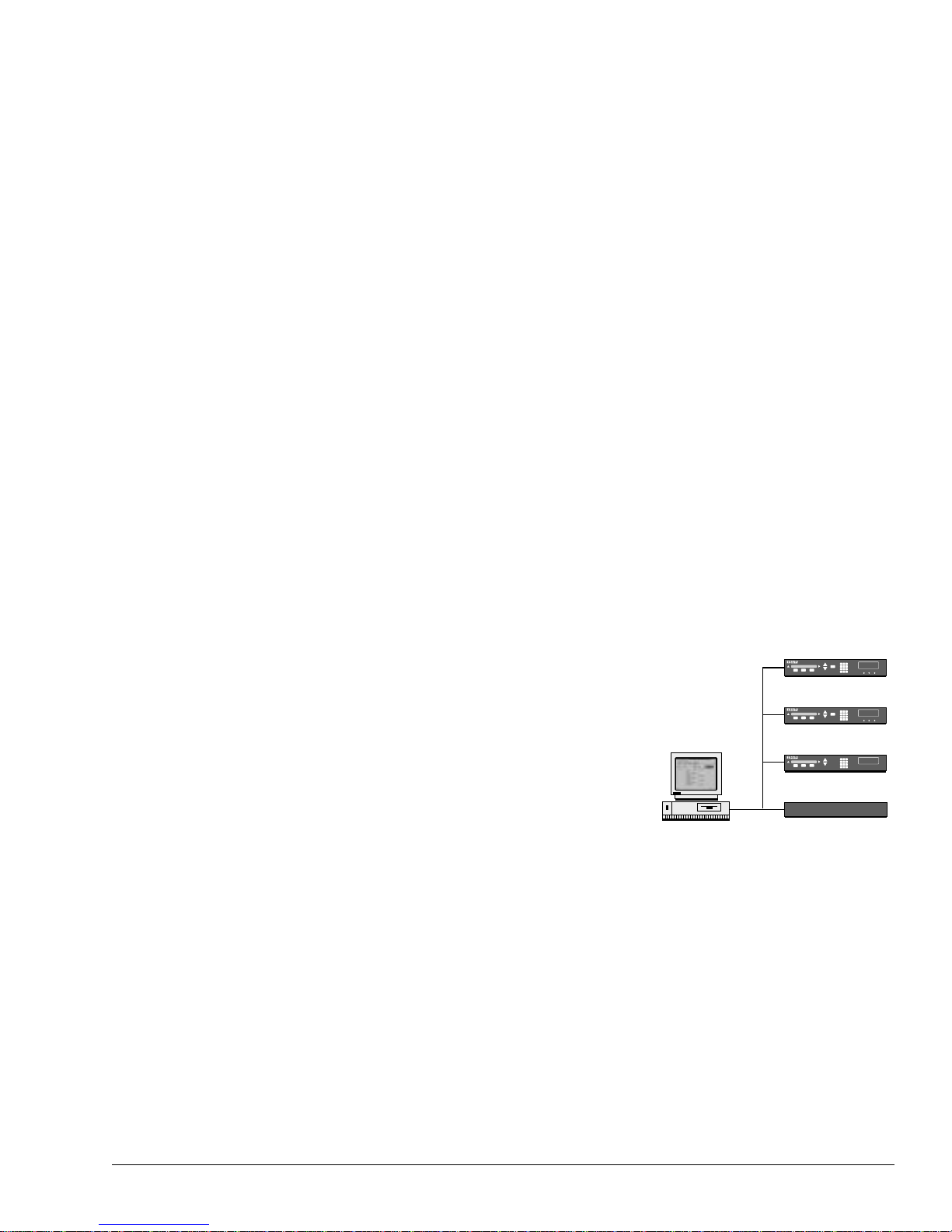
Network Management
Software
Construction The TE3000 is a small, 2RU (90mm/3.15”) high, 21-inch rack
mount chassis with an international auto
-sensing AC power supply
.
To simplify and centralize equipment cont rol,
Tiernan offers a variety of Network
Tiernan Encoder
Management Software (NM S) systems which
allow single or multiple network devices to be
configured, monitor ed, and controlled from a
Tiernan Encoder
central workstation.
Tiernan’s NMS systems implement an
Tiernan Decoder
easy-to-use graphical user interface (G U I)
through which an operator or systems
administrator can:
! Configure all network devices to their site
Workstation
Running NMS
Typical NMS System Managing Multiple Devices
Non-Tiernan Equipment
requirements, including conditional
access, security administration, and event logging
! View and fi lt er network system events, including user configuration changes,
failed connec ti ons, and failed de vic es
! Implement and monitor securi t y measure s incl udi ng discretionary access
control, deletion and reuse, identity and authentication, and auditing
! Customize the NMS software to support non-Tiernan equipment in the
network, providing single point control and monitoring
For information a bout Tiernan’s NMS systems, please contact the T iernan Sales
Department.
TE3000 Overview 3
Page 14

4 TE3000 Overview
Page 15
Installing the TE3000
This chapter provides step-by-step procedures for installing and cabling the
TE3000.
Do not remove the TE3000 top cover! The TE3000 is powered by an exposed,
switching AC power supply which presents an electric shock hazard when the top
DANGER!
Electric Shock
Hazard
CAUTION!
Please Read
Carefully
Placement The TE3000 can be installed on a table top or in a rack. Use the following
cover is removed. Personal injury or damage to the equipment can occur when the
top cover is removed. None of the procedures in this manual require the removal
of the TE3000 top cover.
Before beginning your installation, read the Safety Precautions as the y contain
important safety informa tion and ot her instruc tions required to in stall the TE3000.
guidelines to determine the appropriate installation for your needs:
! If the equipment must be moved frequently, install the TE3000 on a table top
or other flat surface.
! If the equipm ent is going t o be installed permanently, install the TE3000 in a
rack using rack mount brackets.
Whichev er install ation is used, always pos ition the equ ipment to allo w easy ac cess
to the rear panel and provide adequate ve ntilation.
To properly install the TE3000, follow the instructions provided in the appendix
on table top and rack mount installation instructions.
2
Powering On The
TE3000
Ventilation
The TE3000 must be positioned to receive adequate ventilation at all times. The
cooling fan p ulls ai r in th rough the side vent s, circ ulates the air, and exhausts it out
the side vents. The minimum air flow clearance required on both sides of the
chassis is three (3) inches.
The rear panel AC power supply interface includes a fuse holder, and an IEC 320
power cord receptacle. The On/Off (—/0) power switch is located on the front
panel. The typical TE3000 configuration requires 125 amps.
The TE3000 uni t is powered by an aut o-sensing, auto-ranging AC switchin g
power supply. The supply accepts 100 to 240 VAC nominal input voltage levels
cycling at 50 to 60 Hz. A 3.15 amp fuse on the rear panel protects the power
supply from excessive current.
AC Power Cords
The TE3000 shipping kit includes two AC power cords, one for North American
applications, specifically the United States and Canada, and the other for
international applications.
Installing the TE3000 5
Page 16

CAUTION!
Please Read
Carefully
CAUTION!
Please Read
Carefully
AC wiring must be done in accordance with governmental sta ndards and codes in
effect at the TE3000 installation site. Refer to the Safety Precautions for
additional information.
North American Applications One cord has an IEC-compatible female
plug on one end and a North American male plug on the other. This cord is UL
and CSA approved up to 125VAC at 10A. This cord is ready to use with no user
wiring required.
International Applications The international cord has an IEC-compatible
female plug on one end and three stripped and tinned ba re wires on the other end.
This cord is approved by many international safety agencies, including VDE, up
to 250VAC at 6A.
Connecting to a Power Source
To connect to an AC power sourc e , follow these st eps:
1. Select an AC power cord. If an international po wer cord is selected, attach a
connector in accordance with local regulations and laws.
2. Ensure th e TE3000 power switc h is in the Off, or 0, posit io n.
3. Connect the female plug of the AC power cord to the AC power receptacle on
the TE3000 rear panel.
4. Connect the male plug of the AC power cord to an external A Cpower
conditioning surge suppressor.
5. Connect the AC power conditioning surge suppressor to an A Coutlet.
Corrupted AC input power can interrupt TE3000 operations and cause permanent
damage to the unit. You should purchase and install a commercially available,
external AC power conditioning surge suppressor to protect the TE3000 against
power spikes and line transients.
Power-up Sequence
Once the cabling and interconnections for the TE3000 are completed, you may
power-up the unit. The TE3000 power switch is a rocker switch located on the
front panel.
The power switch is lab elled with a
position, while the
0
represents th e Off position.
To power up the TE3000, press the po wer switch to the ON, or
—
and an 0. The — represents the On
—, position. The
power -on cycle takes approximately three to four minutes to comp lete, as the unit
performs exte nsive self-diagnostics in this time period. During the powered-up
cycle, the TE3000 displays
Initializing
, and the tri-colored Status LED
illuminates and may flash. After the unit is initialized, the LCD displays the SD
Encoder main menu.
SD Encoder
[ Config ] Status
→
6 Installing the TE3000
Page 17
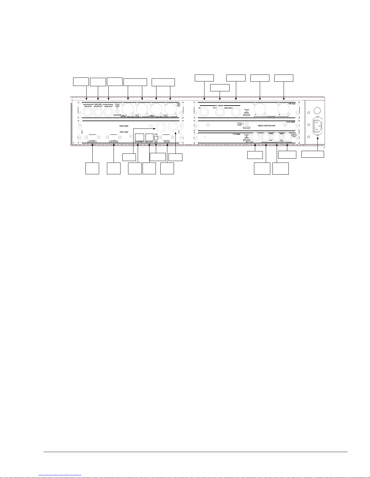
Rear Panel Connections All TE3000 external conne ctions are located on the rear panel, as shown in the
following illustration.
Analog
Video In
Aux
Data A
Analog
Video Out
Analog
Genlock
Aux
Data B
Analog Audio A
Right Left
Tx IF
Out
Ethernet
Control
Analog Audio B
Right Left
TX IF Out
DTE DCE
Fault
Relay
Switch
Mod ASI In
RS-232
Control
Mod
ASI In
D1 Video In
D1 Video
Out
D1 Video
Genlock
Audio Input
A
ASI
TS In
TS Out
Primary
ASI
Audio Input
SMPTE-310
TS Out
Secondary
ASI
B
TS Out
Video Ports The TE3000 provides connections for both analog and digital video.
Analog Video Ports (TVIP6021)
The TE3000 analog video ports, found on the TVIP-6021, are as follows:
! Analog Video In
! Analog Video Out
! Analog GenLock
Fuse
IEC Power Cord
Receptacle
Analog Video In Analog Video In is a female BNC connector with 75Ω
impedance, accepting a NTSC or PAL composite analog video input that is
1.0Vpp nominal level. The analog composite video input must be compliant with
SMPTE 170M NTC, ITU-R BT.470, and PAL-I/B/D. The connector shell is
connected to signal ground.
Connect the video input cable to the Analog Video In connector on the rear panel.
Analog Video Out Analog Video Out is a loop through of the composite
video in signal on a female BNC connector. This connector should be terminated
with a 75Ω load to maintain proper video levels through the system.
Analog GenLock The Analo g GenLock is a femal e BNC conn ector with 75Ω
impedance. The 27 MHz source clock is derived from one of the following
sources:
! Incoming video
! External analog genlock input, SMPTE RP154 (NTCS), EB UD23, and EBU
D25 (PAL)
The external genlock input permits the user to hot switch the video input during
the vertical blanking interval without losing synchronization. Typically GenLock
is connected to a black burst house sync signal in a video plant.
Installing the TE3000 7
Page 18

Digital Video Ports (TVIP 6001)
The TE3000 digital video ports, found on the TVIP-6001, are as follows:
! D1 Video In
! D1 Video Out
! D1 Video GenLock
D1 Video In D1 Video In is a female BNC connector, with 75Ω impedance.
The port accepts a 525 line or 625 line D1 serial digital video input that is format
compliant with SMPTE-259M. The video input is expect ed to be 270 Mbps, with
10bit ITU-R Rec. BT.601 sampled video in 4:2:2 (YCbCr) component format.
Connect the digital video input cable to the D1 Video In connector on the rear
panel.
D1 Video Out D1 V i deo Out is a loop through of the digital video in signal on
a female BNC connector. When the TE3000 is powered off, D1 Video Out is a
passive loop through. When the TE3000 is powered on, the D1 Video Out is an
active loop through driven by a 75Ω driver.
D1 Video GenLock The D1 Video GenLock is a female BNC connector with
75Ω impedance. The port accepts external SMPTE 259M input. When activated,
the D1 Video GenLock is used as the timing reference for the 27 MHz MPEG
system clock of the TE3000.
The external genlock input permits the user to hot switch the video input during
the vertical blanking interval without losing synchronization. Typically GenLock
is connected to a black burst house sync signal in a video plant.
Audio Ports The TE3000 provides the following audio input connections:
! Analog audio on the TVIP-6021
! Digital audio on the TVIP-6001
Analog Audio (TVIP6021)
The TE3000 has two sets of analog audio input ports located on the TVIP-6021:
! Analog Audio A Right and Left
! Analog Audio B Right and Left
The ports can be co nfigured for two stereo or four
independent analog mono channels.
Each port has a female XLR connector with high
impedance (>10k Ω) termination.
The pin assignments for all the analog audio ports are
listed in the following table.
Audio Port Pin Assignments
Pins Signal
1Gnd
2+
3–
8 Installing the TE3000
Page 19

Digital Audio Ports (TVIP6001)
The TE3000 has two digital audio input ports locat ed on the TVIP-6001:
! Audio Input A
! Audio Input B
Each port has a female XLR co nnector wi th 110Ω. nominal termination. The ports
accept AES/EBU serial di git al input that is complian t wit h ANSIAES3-1992
(ANSI S4.40-1992) recommendations. The ports are typically configured for two
stereo channels.
Aux Data A and B Ports Aux Data A and Aux Data B ports are located on the TMAC-6000. These ports
are female DB-9 connectors. Each channel can be independently configured as
synchronous or asynchronous.
Synchronous Configuration
In synchronous configuration, the ports accept RS-422 input at 1 kbps to 4 Mbps.
The auxiliary Data A and Data B synchronous port pin assignments are list ed in
the following table.
Aux Data Port Pin Assignments: Synchronous – RS-4 2 2
Pins Signal Direction Definition
1Unused — —
2 ST+ Out Send Timing
3 SD+ In Transmit Data
4 TT– In Term Timing
5 GND — Ground
6 ST– Out Send Timing B
7Unused — —
8 SD– In Transmit Data
9 TT+ In Terminal Timing
Shell GND — Ground
Configuring the DTE and TE3000 Clock Interfaces
After you have cabled the data termination equipment (DTE) to the TE3000, you
must deter m in e the most effective TE3000 and DTE clock source arrangements.
There are three different ways to configure the clock interface for the TE3000 and
the DTE:
! Clock Interface Configu ration 1 is the most rel iable cloc k source arrange ment.
This configuration requires the DTE to provi de a clock (TT) synchronous
with the data (SD) to the TE3000.
! Clock Interface Configuration 2 is the second most reliable clock source
arrangement. This conf igur ation is u sed when the DTE ca nnot turn a round the
ST, but has an internal clock source tha t can be pro vid ed as TT to the TE3000.
! Clock Interface Configuratio n 3 is the least rel i abl e clock source arrang ement
— it should only be used if the first two clock configurations cannot be used.
In this configuration the TE3000 is configured to use ST to latch the data.
Installing the TE3000 9
Page 20
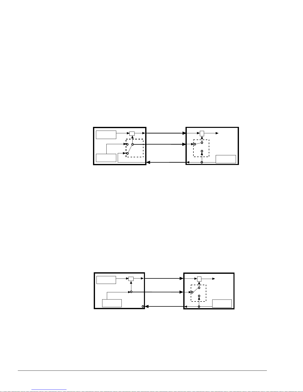
Clock Interface Configuration 1 The most reliable auxiliar y data channel
clock source configuration requi re s t h e DTE t o p rovide a clock (TT) synchronous
with the data (SD) to the TE3000. This scenario allows the TE3000 to latch the
data using a clock th at has tr aveled the same path as the data, which ensures that
both the clock and the data are received in phase at the TE3000.
The following bl ock dia gram shows the clock configuration for a DTE conf i gured
to turn around the ST clock source, and a TE3000 auxiliary data channel
configured for an external clo ck source.
Notice in the illustration that the switch for the TE3000 auxiliary data channel
clock source is conf igured f or ext ernal e v en tho ugh the TE3000 is provi ding ST to
the DTE.
Data
Internal Clock
DTE
Int
Source
Ext
Source
Timing Data
ST
Switch
ST
Data SD
Clock TT
Clock ST
TT
SD
ST
TE3000
Latching Data
Switch
Ext
Source
Int
Source
To TTM
Internal Clock
ST
In this configur ation, the TE3000 provide s cloc k (ST) to the DTE. The switch for
the DTE clock source is configured to accept the external clock (ST) provided by
the TE3000. The DTE uses the ST to time the data, sends the data to the TE3000
on SD, and returns the ST to the TE3000 on TT. The TE3000 uses TT to latch the
data.
The TE3000 auxiliary dat a channel must be configured for an external clock
source to accept TT from the DTE.
Clock Interface Configuration 2 If the DTE cannot tur n around th e ST, but
has an internal clock source that can be provided as TT to the TE3000, use this
option to configure the auxiliary data channel.
The follo wing block diagram shows the clock configuration for a DTE providing
an internal clock source as TT to the TE3000.
In this configuration, the DTE clock is set to internal and the TE3000 auxiliary
data channel clock sourc e is set to externa l. The DTE uses its interna l clock source
to time the data, sends the data to the TE3000 on SD, and sends its internal clock
to the TE3000 as TT. The TE3000 uses TT to lat ch the d ata. The TE3000 au xiliary
data channel must be configured for an external clock source.
10 Installing the TE3000
Data
Internal Clock
Int
Source
Timing Data
Data SD
Clock TT
Clock ST
TT
SD
Source
Source
ST
TE3000DTE
Latching Data
Switch
Ext
Int
To TTM
Internal Clock
ST
Page 21

Clock Interface Configuration 3 If the DTE cannot turn ar ound the ST, and
does not have an internal clock source that can be provided as TT to the TE3000,
configure the TE300 0 to us e the ST to la tch t he data . However, this scenar io is not
recommended and should be considered only if neither of the other two clock
source configurat i ons can be used.
The following bl ock dia gra m sho ws t he cloc k conf i gurati on for a DTE conf i gured
for an external clock and a TE3000 auxiliary data channel configured for an
internal clock.
CAUTION!
Please Read
Carefully
Data
DTE
Timing Data
ST
Data SD
Clock ST
TT
SD
Source
Source
ST
TE3000
Latching Data
Ext
Switch
Int
To TTM
Internal Clock
ST
In this scenario, both the DTE and the TE3000 use ST, but the ST is provided to
the DTE on one path and to the TE3000 on a different path. Depending upon the
length of cable between the DTE and the TE3000, the clock may be received out
of phase at the TE3000. The longer the cable, the further out of phase the clock
will be.
If the internal clock i s used to latch the data, the lengt h of cable between the DTE
and the TE3000 must be limited to one meter (3 feet). Additionally, the auxiliary
data rate must be l imited to not more th an 64 kbps. If the cable length exc eeds one
meter, or if you attempt to process data at rates above 64 kbps, the auxiliary data
may be corrupted.
Asynchronous Configuration
In asynchronous configurations, ports can be configured to accept RS-232 or
RS-422 input at rates of 1200 bps to 38400 bps.
RS-232 The DB-9 connector allows a standard RS-232 DCE connection. The
auxiliary Data A and Data B asynchronous port pin assignments for RS-232 are
listed in the following table.
Aux Data Port Pin Assignments: Asynchronous – RS-232
Pins Signal Direction Definition
1Unused — —
2Unused — —
3 TD In Transmit Data
4Unused — —
5 GND — Ground
6Unused — —
7 RTS In Ready to Send
8 CTS Out Clear to Send
9Unused — —
Installing the TE3000 11
Page 22

RS-422 The auxiliary Data A and Data B asynchronous port pin assignments
for RS-422 are listed in the following table.
Aux Data Port Pin Assignments: Asynchronous – RS-422
Pins Signal Direction Definition
1Unused In —
2 CTS+ Out Clear to Send
3 RD+ In Transmit Data
4 RTS– In Request to Send
5 GND — Ground
6 CTS– Out Clear to Send
7Unused — —
8 RD– Receive Data In
9 RTS+ In Request to Send
Remote Unit
Connections
A remote unit can be connected through either of two ports located on the
TMAC-6000:
! RS-232
! Ethernet Control
RS-232 Control Por t
The RS-232 port is a DB-9 female connector. The port can be configured as a
DTE or DCE. The default configuration is as a DCE.
DCE Configuration The pinouts for the RS-232 port configured as DCE are
listed in the following table.
RS-232 Port Pin Assignments: DCE
Pin # Signal Direction Signal Definitions
1 DCD In Carrier Detect
2 RXD In Receive Data
3 TXD Out Transmit Data
4 DTR Out Data Term inal Ready
5 GND — Ground
6 DSR In Data Set Ready
7 RTS Out Request to Send
8 CTS In Clear to Send
9 RI In Ring indicator
Shell GND — Ground
12 Installing the TE3000
Page 23

DTE Configuration The pinouts for the RS-232 port configured as DTE are
listed in the following table.
RS-232 Port Pin Assignments: DTE
Pin # Signal Direction Signal Definitions
1Unused— —
2 TXD Out Transmit Data
3 RXD In Receive Data
4 DSR In Data Set Ready
5 GND — Ground
6 DTR Out Data Terminal Ready
7 CTS In Clear to Send
8 RTS Out Request to Send
9 RI In Ring indicator
Connecting to the RS-232 Control Port To connect a remote unit to the
TE3000 through the RS-232 control port, you need a cable that is the appropriate
length for the application. The cable must be made to the following specifica tions:
! RS-232 electrical
! DB-9 female connector on one end
! An appropriate connector for the remote unit on the other end
A 6-foot lo ng direct connect DB-9 male to DB-9 female cable is included in the
TE3000 shipping kit.
Using the direct connect cable provided with the TE3000, attach one end to a
remote unit and the other end to the RS-232 control port.
NOTE...
Ethernet Control Port
The Ethernet control port is an RJ-45 connector. Remote control using this port
requires the fo llowing:
! Tiernan Network Management Software (NMS) program
! Category 5 UTP patch cable (not supplied)
Connecting to a Network Using the Ethernet Port You can connect the
TE3000 to a LAN using the Ethernet port, which enables you to monitor and
control the TE3000 through a remote unit not directly connected to the TE3000.
When connecting the TE3000 to a LAN using Ethernet, contact your Information
System department to coordinate installation and setup.
Perform the following steps to connect to the network using the Ethernet port:
1. Connect a Category 5 cable with RJ-45 connectors (standard ethernet cable)
between the TE3000 Ethernet port and a LAN hub.
2. Assign the device a unique IP address, if necessary.
The TE3000 default IP address is 0.0.0.0. Contact your Information Systems
department for a valid IP address .
Installing the TE3000 13
Page 24

To change the IP address using the front panel:
a. Select Config>Comm>Network>IP Addr
b. Using the keypad, enter the IP address in the format xxx.xxx.xxx.xxx
where xxx is a decimal number between 0 and 999.
c. Press the Enter button
To change the IP address using a remote unit, issue the
MC IP XXX.XXX.XXX.XXX command where XXX is a decimal number
between 0 and 999.
3. Assign additional network information, if necessary. Depending on the
configurati on of the LAN, you may need to enter additional parameters
including:
"
Ethernet IP address mask (IP subnet mask)
"
Ethernet IP gateway
4. From a personal computer connected to the LAN, try to ping the TE3000. At
the command prompt of the personal computer, typ e ping <TE3000 IP
address> where <TE3000 IP address> is the address assigned in step 2.
If a reply is received, the TE3000 is correctly configured .
For information on establishing remote communications or on Ethernet
commands, refer to the chapter on using a remote unit.
DTE/DCE Switch The DTE/DCE switch is used to change the configuration of the RS-232 port.
When the port is conf igured as DCE, use a standar d cable for th e computer Comm
port. In this configuration, the port suppo rt s all of the signals required for ba sic
modem support:
! Rdata ! Tdata
! DTR ! DCR
! CTS ! RTS
! DCD
When the port is configur ed as DTE, use a null modem cable to connec t the PC to
the TE3000.
Fault Relay The Fault Relay is an RJ-11 connector. The fault relay is used in a redundant
configurat io n. In this configurati on inp ut is fed from distribution amplifiers into
each of two TE3000s. A Tiernan redundancy switch monitors the output through
the Fault Relay. If the primary TE3000 faults, the secondary TE3000
automatically takes over operation.
A relay fault condition is defined as:
! A unit power failure
! Unit power switch turned off
! Unit is unplugged
! A unit hardwa re failure
The fault condition is indi cate d by contac t closur e be tween pins one (1) and three
(3) and open contacts between pins one (1) and si x(6).
The non-fault condition is indicated by contact closure between pins one(1) and
six (6) and open contacts between pins one (1) and three (3).
14 Installing the TE3000
Page 25

The illustration indicates the physical locations of pins 1
and 6 within the fault relay port, as viewed from the rear
panel.
When the fault relay detects a fault cond ition, the f au lt
relay trips , an d the Status LE D located on the TE3000
front panel illuminates red.
Pin 1 Pin 6
Transport Connection
Ports
The TE3000 multiple xer outputs an ASI transport stream with a variab le rate of 1
to 7 0Mbps. This transport stream is the combination of the video, audio, and
auxiliary data streams in an MPEG-2 compliant transport stream. Depending on
the operating mode, the transport stream is either:
! Input to the modulator or the multiplexer of another TE3000 where it is
multiplexed with another transport stream before being output
! Output to an exte rnal satellite modulator
Operating Modes
The two TE3000 operat o r modes are:
! Single channel per carrier (SCPC)
! Multiple channel per carrier (MC P C )
SCPC Mode In SCPC mode, the ASI transport stream is connected from the
TE3000 multiplexer to the internal modulator of the same TE3000. In this mode,
the modulator supports tran sport st ream data rates fr om 1 up to 18 Mbps in SCPC
mode, depending on the FEC rate selected. Output symbol rates range from 1 to
20 MSps.
MCPC Mode In MCPC mode, the ASI output of one TE3000 is fed into the
multiplexer of another TE3000 so that the output of the two encoders are
multiplexed in a single transport stream. The signal from a series of TE3000s can
be combined in this way. The combined transport stream is then output to the
modulator of the f inal TE3000 in the chain.
In MCPC mode, the modulator supports transport stream data rates from 1 to
32 Mbps, de pending on the FEC rate selecte d. Output symbol rates range from 1
to 20 MSps. For applicat io ns requiring higher data rates, an external modulator
can be used instead of the TE3000 integrated modulator.
Connections
The TE3000 ports used to connect the transport stream to the modulator and the
MCPC chain are:
! ASI TS In
! ASI Out Pri (primary ASI out)
! ASI Out Sec (secondary ASI out)
! SMPTE -310
! Mod ASI In
ASI TS In ASI TS In is a female BNC connector with 75Ω impedance. When
the encoder is configured for MCPC operation, this port accepts the transport
stream from either ASI Out port of another encoder.
Installing the TE3000 15
Page 26

ASI Out Primary ASI Out Primary is a female BNC connector with 75Ω
impedance. The port outpu ts a DVB- compliant ASI transport stream at rates
between 1 and 70Mbps.
ASI Out Primary is used for normal operation and is typically cabled to the Mod
ASI In connector with a short (14”) coaxial cable.
The transport stream output on ASI Output Primary is a spare and is not bypassed
in case of failure.
ASI Out Secondary ASI Out Secondary is a female BNC connector with
75Ω impedance. The port outputs a DVB-com pliant ASI transport stream at rates
between 1 and 70Mbps.
ASI Out Secondary port can be us ed to output the t ransp ort s tream of one TE3000
to the multiplexer of another TE3000 for MCPC operation. In this configuration,
this port is cabled to the Mux ASI In port of the next TE3000 in the MCPC chain.
If a fault conditio n or power failure exists, the input tran sport stream, w h ich is
connected to ASI TS In, is bypassed directly to ASI Out Secondary through a
passiv e by pass r elay. This ensures th at onl y the progr am assoc iate d with the f ai led
TE3000 in an MCPC chain of encoders or in a redundant configuration is
interrupted by the failure.
ASI Out Secondary can also be used to monitor the transport stream.
SMPTE -310 This port is used to output a SMPTE-310 compat ible transport
stream.
Modulator Output to
Upconverter
Connections
Mod ASI In Mod ASI In, located on the TMOD-6000, is a female BNC
connector with 75Ω impedance. The po rt accepts the transport stream from either
ASI Out port.
The Mod ASI In transport data is processed according to DVB standards and
output from the integrated TE3000 QPSK modulator on the port labeled Tx IF
Out.
The internal modulator outputs a modulated IF signal, which is connected to an
upconverter.
Connections are made through the Tx If Out port. This port is a female BNC
connector that outputs a 70 Mhz, DVB-compliant, QPSK modulated, FEC
encoded IF signal at symbol rates from 1 to 20 MSps.
Before you cable the modulator output to the upconverter, turn the modulator off
until you are ready to begin satellite transmissions.
T o cable th e modulator out put to an upconverter , connect the output of the i nternal
modulator from Tx IF Out to an IF-to-RF upc onverter.
16 Installing the TE3000
Page 27
Using the Front Panel
This chapter describes the following TE3000 front panel information:
! Components
! Navigating through menu s
! Description of menus, parameters, and options
3
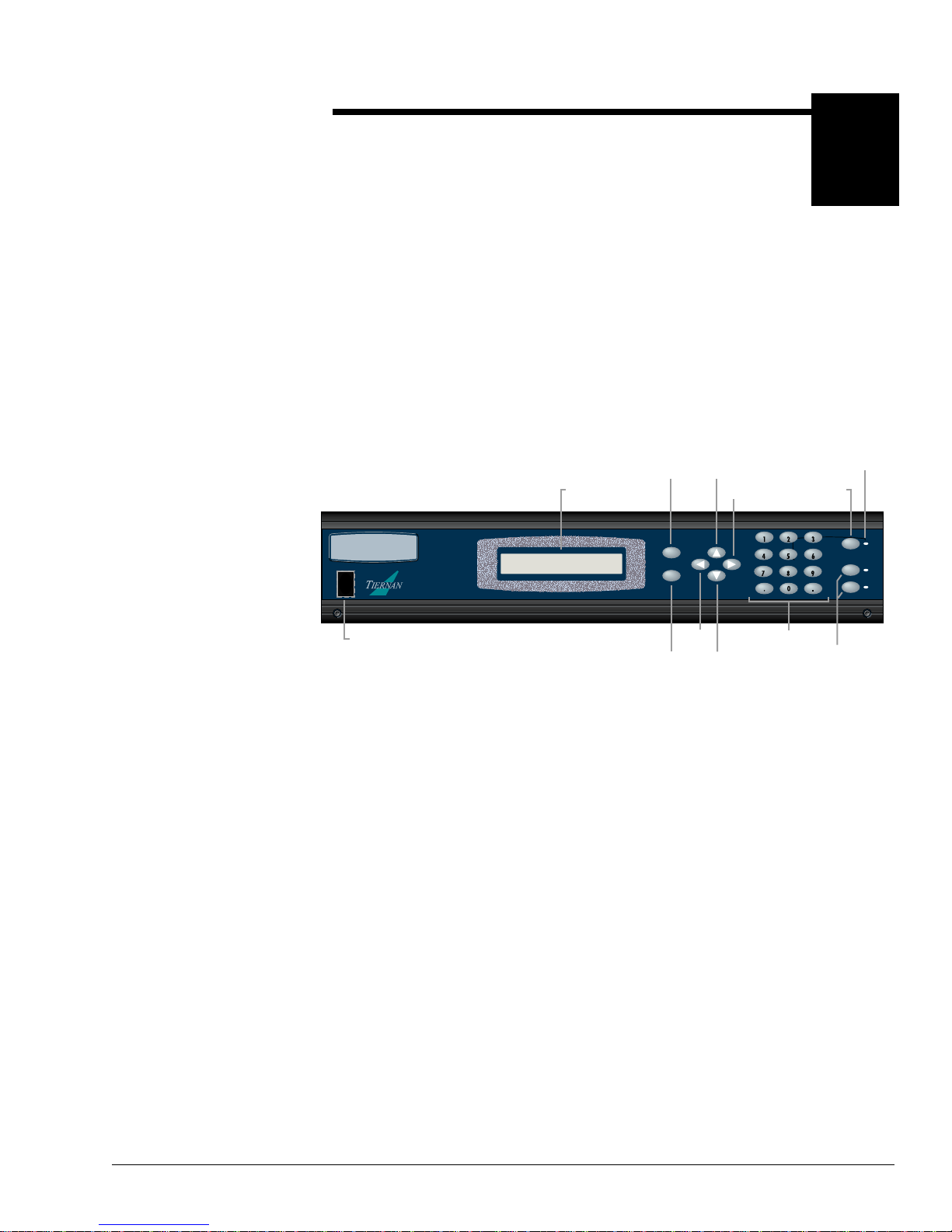
Front Panel
Components
The front panel enables you to easily and efficiently configure and monitor the
TE3000.
Tri-color
Status
Button
STATUS
CARRIER
MOD
Modulator
and LEDs
Status
LED
TE3000
MPEG2 ENCODER
|
0
On / Off
Switch
LCD
Display
Enter
Button
ENTER
EXIT
Exit
Button
Button
Left
Button
Down
Button
Up
Right
Button
GHI JKL MNO
PQRS TUV WXYZ
Alpha-numeric
ABC DEF
Keypad
Control Buttons
The front panel consists of:
! LCD – displays menus, parameters, informat io n, and message s
! Enter button – used to select a menu item, issue a command, or set a
parameter
! Exit button – used to scroll up to a previous menu level or leave a parameter
without changing it’s option
! Left and Right buttons – used to scroll within the current menu level, or to
scroll through a list of parameters
! Up and Down b utt ons – used to s croll thro ugh par ameter options and increase
and decrease parameter values
! Alpha-numeric keypad – used to enter alphabetic and numeric parameter
values
! Status button – hot key which toggles between the current front panel menu
and the current faults list
! Status LED – tri-color LED alerts you to status and fault conditions
! Modulator control but tons and LEDs – thes e two bu tt ons affect the power and
form of the output IF transmit carrier from the encoder:
"
Carrier – enables carrier wav e at nominal power
"
Mod – enables modulated carrier at nominal power
Using the Front Panel 17
Page 28
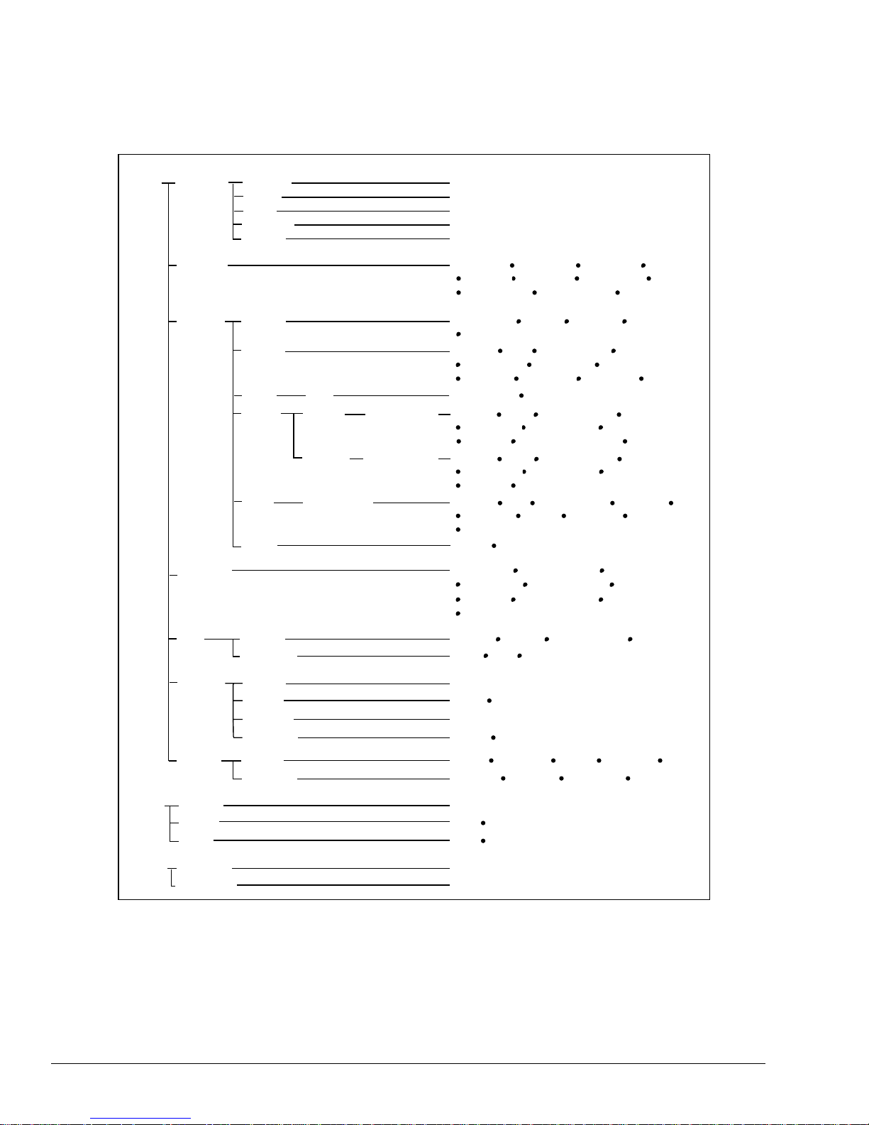
TE3000 Menu Structure
SD Menu Submenu Submenu Submenu Parameters
Config
Presets
Output
Service
Tx Strm
Restore
Save
New
Rename
Delete
Setup Service ID Name
Video
VBI CC Tiernan CC ATSC CC
Audio
Data Data A to B Enable Comm Mode Interface Baud
PCR
Digital Slot 4A to 4B
Analog
Submenu
Slot 1A to 1B
<list of configuration sets>
<list of configuration sets>
<enter new configuration name>
<list of configuration sets>
<list of configuration sets>
Out Mode
Tx Freq
Mod Source Tx Power-up Mod Status
Minor Channel
Enable
Format Ctrl Data Rate
Chroma
Enable Compression
Data Rate
Format Delay
Enable Compression
Data Rate
Format Delay
Data Bits Parity Stop Bits Data Rate
Clock Source
Delay Transmit Rate
Rate Calc Redund StateChannel Mode
Table Type
ExtRate
LocRate
Mod State Code RateData Rate
Spect InvertTx Power SymRate
Provider Major Channel
Input Source
PID
Resolution
Optimize
PID Source
Sample Rate
D1 Audio Chnl Pair
PID Source
Sample Rate
PID
Ext TS Enable Ext TS Status
Loc TS Enable Loc TS Status
Format
Timebase
Data Resolution
Data Resolution
Delay
CA
Control
Comm
Status
Version Firmware <firmware version label>
Current
History
Relay
Hardware <version label of installed modules>
Setup
IRD Cfg
Reset
Clock
FP Lock
Serial
Network
"Press ENTER to Reset"
Date Time
ScreenSaverDisplay
State Password
Baud Data Bits Parity Stop Bits Flow
IP Addr
<list of current faults>
List
List
Enable
List
IP Mask IP Router TMA
Clear
Clear
Scramble Key Message PIDFormat
DeleteNew
18 Using the Front Panel
Page 29

Navigating Through the
Menus
LCD Display LCD Symbols
The front panel LCD display and buttons were designed to help you navigate
through the TE3000 menu structure quickly and efficiently.
There are six important symbols that appear on the LCD:
! Brackets [ ] ! Asterisk (
! Arrows ! Colon (:)
! Equal sign (=)
)
*
Brackets As you are moving through menu items, brackets indicate which
menu item is currently selected.
Arrows As you are navigating through the TE3000 menus, a left and right
arrow will often display on the LCD. Depending upon where you are in the menu
structure, this arrow denotes the following information:
! At a menu level the arrow indicates that there are additional items availab le at
that current menu level
! In a list of param eters the arrow indicates that there are additional items
available in that parameter list
Asterisk While the TE3000 is executing a command or setting a parameter
option, an asterisk (*) appears on the LCD, indicating that the TE3000 is
processing information. When the asterisk disappears, the process is complete.
Equal Sign Most parameters, though not all, can be modified in order to
configure the TE3000. Configurable par ameters are followe d by an equal sign,
denoting that the parameter can be modified.
Colon There are some paramete rs that are automatically se t for your system o r
that are query-only paramet ers. These type of parameters are followed by a colon.
When a parameter is followed by a colon, that parameter can be viewed but not
changed.
LCD Text Formats
All menus, parameter options, and system information are displayed on the front
panel LCD.
Menus All menus are displayed in the following format.
Service Menu
[ Setup ] Video
! The first li ne identifies the current menu level. This example shows the
→
Service menu.
! The second line displa ys two of the avail ab le me nu ite ms.
! The brackets indicate which menu item is selected. In this example, the vi deo
menu item is selected.
! The arrow, when displayed, signifies that there ar e additional menu items
available at that level.
Using the Front Panel 19
Page 30

Parameter Options All parameter options are displayed in the following
format.
Auxillary Data A Menu
Data Bits = 8
! The first line identifies the current menu level, in this example, the Auxiliary
→
Data A menu.
! The second line displays the parameter, Data Bits, and its current setting of 8.
! The equal sign (=) denotes that this parameter can be modified. If this
parameter was followed by a colon (:) the parameter would be view-only.
! The arrow indi cates that there are additio nal Data A parameters.
Information Information, such as current faults, faults in the history log, and
system me ssages are displayed as ASCII text strings as shown in the following
example.
Current Faults
VI.A Loss of Input
! The first line identifies the type of information displayed, in this example,
current faults.
! The second line lists one line of information, in this example, the most recent
current fault.
! There is no arrow displa yed, signifying that there are no additional current
faults.
Front Panel Navigation
Buttons
The follo wing front panel buttons ar e used to move through menus in order to
issue commands and view status and fault information:
! Right and Left buttons ! Enter button
! Exit button ! Up and Down buttons
! Numeric keypad ! Status button
Right and Left Buttons The Right and Left buttons are used when either a
right or left arrow is displayed on the LCD. These buttons move you through the
menu structure in the following manner:
! At a menu lev el these buttons move the selection brackets [ ] and scroll right
and left, (forward and backwards), respectively, through all available menu
items at that current level. When the last menu item is displayed, the TE3000
continues scrolling through the list again. The following graphic illustrates
how the right button functions at a men u level.
Press Right Arrow
Brackets Move to
Next Menu Item
SD Encoder Menu
[ Version ]
SD Encoder Menu
[ Config ] Status
Press Right Arrow
Brackets Move to
Next Menu Item
SD Encoder Menu
Config [ Status ]
20 Using the Front Panel
Page 31

In a parameter list, the right and left buttons scroll through the parameter list.
!
When the last parameter is reached, the TE3000 scrolls through the list again.
LCD Display
Video Encoder Menu
Enable On
Input Source Digital
Press right button; the next parameter displays
Press right button; the next parameter displays
Delay 0
Press right button; system returns to
first parameter in list
Using both the right and left b uttons en ables you to sc roll thr ough a paramete r
list in eithe r a fo rw ard or backward m otion.
LCD Display
From Enable, press left button;
system returns to last parameter
Video Encoder Menu
Enable On
Input Source Digital
Timebase Video Input
Delay 0
Press left button;
the previous parameter displays
Press left button;
the previous parameter displays
If you accidentally scroll past the required parame ter, you simply use the
appropriate left or right button to go back to the required parameter.
Enter Button The Enter button is used to :
! Select the menu item displayed in brackets [ ] on the LCD
! Issue a command
! Set a new parameter option
To select a menu item, you use the Left/Right buttons until the brackets
encompass the menu item, then press the Enter button. The Enter button moves
you to the selected submenu.
To issue a command, such as the clear history log command , press the Enter
button to execute the command.
To set a parameter option, such as a new vid eo fra me rate, press the Enter button.
The TE3000 is configured with the new parameter value. The new values are then
stored in nonvolatile memory .
Exit Button The Exit but ton moves you through the menu structure in the
following manner:
! At a menu level, the Exit button moves you up one menu level. If you are at
the very top of the menu structure, at the SD Encoder main menu, you are
moved to the beginning of this menu when you press the Exit button.
Using the Front Panel 21
Page 32

! In a parameter list, the Exit button moves you up to the previous menu leve l.
SD Encoder Menu
[ Service ] Tx Strm
Press Exit From any Menu;
Service Menu
[ Setup] Video
Press Exit From any Parameter;
System Returns to the Previous Menu Level
Video Encoder Menu
Enable On
Input Source Digital
Delay 0
System Returns to the
Previous Menu Level
Up and Down Buttons Once a parame te r is di spl ay ed, use t h e Up a nd Down
buttons to scr ol l thr ough its avail abl e options.
The Up and Down buttons cause the option to flash, indicating that you can
modify that option. Once the option is flashing, you can continue to press the Up
and Down buttons to scroll through the list of avai l able options.
The Up and Down buttons will also increase and decrease the numeric value, if
they are pressed before any keys on the keypad are pressed.
Alpha-numeric Keypad The alpha-numeric keypad is used to enter both
alphabetic and numeric parameter values.
Alphabetic Entries — when entering values in an alpha-numeric field, the
following alphabetic and numeric characters are displayed when a key is pressed:
Key Character Displayed
1 . , ? ! - 1
2A B C 2
3D E F 3
4G H I 4
5J K L 5
6M N O 6
7 P Q R S 7
8T U V 8
9W X Y Z 9
0 space 0 ‘ +
The first pre ss of a numbe r key displays the first character in the set; sequential
presses of the same key advance through the set, in a circular fashion. The cursor
is advanced by either pressing another number key, or by pressing the right arrow
key.
For example to enter the word
ALL
which has two charac ters in the same
characters set, the following keys would be pressed:
2
!
!
! → advances the cur sor so the next lett er can be selected
!
555
555
selects L
selects A
selects L
22 Using the Front Panel
Page 33

A space can be entered by either a single press of the “0” key, or by two or more
presses of the ri ght cursor key.
For example, to enter the words
LA Default
the following keys would be
pressed:
! 555 selects L
! 2 selects A
! 0 selects space
! 3 selects D
! → advances the cur sor so the next lett er can be selected
! 33 selects E
! → advances the cur sor so the next lett er can be selected
! 333 selects F
! 2 selects A
! 88 selects U
! 555 selects L
! 8 selects T
! Enter to issue the command
Numeric Entries — When entering values in numeric field, you simply type the
required numeric value using the keypad and press Enter.
The default value that is initially displayed disappears upon the first numeric key
press. Once a numeri c ke y is pr essed, th e Up and Down but tons are nonfuncti onal;
they resume their normal functions once the Enter or Exit buttons are pressed.
To enter a negative value, press the minus key (-) on the keypad; this toggles the
value between negative and positive.
Status Button The Status button is a hot key which enables you to
immediately view any faults currently occurring on the TE3000 and then toggle
back to the front panel menu on which you were working.
Issuing Commands To issue a command from the front panel, perform the following steps:
1. Navigate to th e required command or parameter using the Left, Right, a n d
Enter buttons.
2. Change the parameter option as required:
"
Scroll through the options usi ng the Up or Down buttons.
"
If the option requires a numeric value to be entered, enter the value using
either the Up and Down buttons to increment the value or the numeric
keypad to type in the value.
3. Issue the command by pressing the Enter key. An asterisk will briefly display
and then disappear when the system is finished processing the request. The
parameter, with its updated value, is then displayed and does not flash.
"
If the Enter button is not pressed, the option is not changed.
"
While the TE3000 is reconfiguring the parameter to the new value, the
front panel is temporarily disabled.
Using the Front Panel 23
Page 34

Correcting
Mistakes
When the TE3000 conf i gur ation is changed using t he f ron t panel, the changes are
automatically stored in non-volatile memory. The TE3000 automatically restores
to the saved configuration whenever the unit is reset or powere d up .
NOTE...
Selecting Options If you are selecting an option and have not pressed the
Enter button, use the Up or Down buttons to scroll to the correct option.
Using the Keypad If you are entering a value with the keypad, and you have
not pressed the Enter button, you can either:
! Press the Up button to change the value to 0, then enter the correct value
! Press the Down button to delete the numbers, then enter the correct value
Leaving a Parameter If you have not pressed the Enter butt on, you can leav e
a parameter without modifying it by pressing either the:
! Exit button which returns you to the pr evious menu level
! Left or Right buttons which take you to the next parameter
In either situation, the TE3000 w ill ignore a ny values entered and return the
parameter to its original setting.
After Pressing the Enter Button If you accidentally issue an incorrect
parameter val ue to the TE3000, you can correct the error by:
1. Selecting the correct option using the Up and Down buttons. The parameter
will begin to flash.
2. Pressi ng the Enter button to set the correct option.
Example
The follow ing example describes how to move through menus and select options.
In this example the TE3000 video will be enabled.
1. From the SD Encoder main menu select Config.
SD Encoder
[ Config ] Status
→
2. The Configuration menu displays.
Configuration Menu
[ Presets ] Output
→
3. Press the Right button until Service displays, surrounded by brackets. Press
the Enter button to select Service.
Configuration Menu
[ Service ] Tx Strm
→
24 Using the Front Panel
Page 35

4. The Services menu displays. Sel ect the Video option.
Services Menu
[Setup [ Video ]
→
5. The Video Encoder menu displays, showing the first video option and it’s
current parameter setting, which is Enable = Off.
Video Encoder Menu
Enable = Off
6. Press the Up button. The On option displays and begins to flash.
Video Encoder Menu
Enable = On
7. Press the Enter button. When the asterisk stops flashing, the TE3000 has set
the new parameter.
Modulator Control
Buttons
The two modulator control buttons, located at the far right of the front panel,
affect th e po wer and fo rm of the output IF transmit car rier from the encoder. Each
button has an associated LED indicator. Only one of the LEDs is illuminated at a
time. These buttons cause the output carrier to be one of the following:
! Off
! Carrier on — full-power CW (constant wave)
! Modulate on — full-power modulated
A blinking LED indicates that the button is busy implementing its command.
When the command is executed the LED stops blinking. Command execution
takes 5 to 1 0 seconds to co mplete. Each ti me you p ress the bu tton, e v en i f the LED
is blinking, the command is executed.
The purpose of the bu ttons is to allow fast and simple operation of the encoder
when a DSNG operator is coming up on a satellite or taking down a link.
Pressing the modulat or contro l bu ttons caus es the TE3000 to toggle t he modula tor
as follows:
Current Modulator State Key Press Resulting Modulator State
Off Mod Modulate On; Carrier Off
Carrier On Mod Modulate On; Carrier Off
Modulator On Mod All Off
Off Carrier Carrier On; Modulate Off
Carrier On Carrier All off
Modulate On Carrier Carrier On; Modulate Off
Using the Front Panel 25
Page 36

Front Panel Menu
Descriptions
The following table provides detailed descriptions of the TE3000 front panel
menus and commands. The commands are organized in the order in which they
appear on the front panel. Included are:
! Menu level
! Front panel command
! Command function
! Available options for that command or the response format if the command is
query-only
TE3000 Front Panel Menu Descriptions
Front Panel
Command
Function Options/Response Format
Configuration Menu — consists of the following submenus:
Presets — used to quickly and easily re-initialize the encoder using predefined factory default configuration settings your own user-defined
!
configuration settings
Output — used to configure and monitor the TE3000 internal modulator
!
Service — used to setup and configure the video, VBI, audio, data, and PCR services
!
Tx Strm — Transport Stream menu enables you to set and query the TE3000 transport stream system configuration parameters. The configuration
!
parameters set at this level impact which options and configuration parameters are available on other menus.
CA — Conditional Access menu is used to setup the TE3000 for conditional access and to create and modify a list of authorized decoders
!
Control — allows you to control the TE3000 hardware; submenus are Reset, Clock, Display, and FP Lock.
!
Comm — Communications menu is used to set remote control and network features; submenus are Serial and Network.
!
Config>Presets Menu — Consists of four submenus, which enable you to quickly and easily save your own user-defined configuration sets, manage the
user-defined list, and then re-initialize the TE3000 using either your user-defined configuration sets or predefined factory default configuration settings.
These configuration sets are not altered by reset, power cycling, or factory DVB default setting of the encoder.
DVB (default)
Restore initializes the TE3000 using either predefined
factory configuration parameters or the selected
user-stored, site-specific parameters
!
ATSC
!
user-defined configurations, as needed, based on site-specific
!
requirements
Save saves the current site-specific configuration in
non-volatile (flash) memory under the selected
label
Up to 99 user-defined configuration sets may be saved. Configuration sets
must be saved to existing user-defined labels. User-defined labels are set
using the Config>Presets>New feature.
New creates a new user configuration label The configuration label may be up to 15 alpha-numeric characters in length.
Up to 99 user-defined configuration sets may be created. Once the label is
created, the configuration set must be saved using the Config>Presets>Save
function.
Rename changes the label (name) of an existing user
displays the list of existing configuration labels
configuration set
Delete deletes, or erases, the selected user configuration
displays the list of existing configuration labels
set
Config>Output — Used to configure and monitor the TE3000 internal modulator. When you begin the initial TE3000 installation and configuration, the
modulator output (Mod State) should be turned off until you are ready to begin satellite transmissions.
QPSK – the internal modulator is used
Out Mode setting determines if the internal modulator is used
to control the bit rate output of the multiplexer
!
ASI – the internal modulator is not used
!
26 Using the Front Panel
Page 37

TE3000 Front Panel Menu Descriptions (continued)
Front Panel
Command
Data Rate sets the data rate for the output transport stream
Function Options/Response Format
1 to 160 Mbps default: 8.448 Mbps
!
Additional Information: The data rate you enter using this parameter determines the combined transport output of the TE3000
and is the multiplexed collection of the local transport stream and the externally supplied ASI transport stream, including overhead.
You must set the output transport stream data rate to a value that is equal to or greater than the sum of the local transport stream
and the externally supplied ASI transport stream, including overhead. That is:
Mod Input Data Rate = Mux Output Rate
AND
Mux Output Rate >
Local Rate + Externally Supplied Transpor t Stream Rate
The following diagram represents this relationship.
TE3000
Local Rate
TTX-6000
TMOD-6000
Mux Output Rate
Mod Data Rate
Externally Supplied
Transport Rate
Output DVB-Modulator
IF Carrier
If the out pu t rat e is s et to a value that is less than the sum of the internal transport stream and the externally supplied ASI transport
stream, including overhead, the data received at the decoder will be corrupted.
Off – shuts off the TE3000 modulator output (default)
Mod State setting affects the power and form of the output IF
transmit carrier from the encoder
Code Rate sets the code rate for forward error correction (FEC)
of the modulated signal
!
Pure Carrier – CW enabled at nominal power
!
Modulate – carrier enabled at nominal power
!
1/2, 2/3, 3/4, 5/6, 7/8
default: 5/6
Additional Information: The rate selected indicates the number of error correcting bits that will be added to the data stream. For
example, if you select the 5/6 rate, for every 5 bits that are input to the FEC encoder, the FEC encoder outputs 6 bits.
The relationship between the selected code rate and the data stream prior to modulation, and an indication of the degree of error
correction provided by each code rate is shown below.
Viterbi Code Rate Transport Stream Data Rate Error Correction
1/2 Increases by a factor of 2 (100% increase) Maximum
2/3 Increases by a factor of 1.5 (50% increase) Very High
3/4 Increases by a factor of 1.33 (33% increase) High
5/6 Increases by a factor of 1.2 (20% increase) Moderate
7/8 Increases by a factor of 1.14 (14% increase) Low
Tx Freq sets the modulator carrier frequency 52.0 to 88.0 MHz
default: 70.0 MHz
Additional Information: The acceptable frequency range is implemented with a pass band filter that filters out all frequencies
below 52000000 Hz and above 8800000 0Hz.
When selecting a carrier frequency, take into account the satellite bandwidth required for transmission. If you select a carrier
frequency that is too close to either end of the valid range, the modulated carrier may be clipped by the pass band filter. For
information on calculating the satellite bandwidth, refer to the Config>Output>Sym Rate parameter.
Tx Power sets the output transmit power of the TE3000
modulator
Spect Invert used to instruct the modulator to invert, or not
invert, the modulated IF output spectrum
-20.0 to -5.0 dBm
default: -5.0 dBm
normal – modulated IF output is not inverted (default)
!
inverted – modulator inverts the I Foutput spectrum
!
Inverting the IF output spectrum eliminates spectral
inversion in the RF chain caused by selecting lower
side-band images of an upconverted carrier.
Using the Front Panel 27
Page 38

TE3000 Front Panel Menu Descriptions (continued)
Front Panel
Command
Function Options/Response Format
SymRate sets the current transmission symbol rate 1.0 to 20.0 MSps
default: 5.500187 MSps
Additional Information: The symbol rate is the number of symbols required to transmit the data stream over a satellite link using
quadrature phase shift keying (QPSK).
The symbol rate is automatically calculated based on the modulator input transport stream data rate, the Viterbi code rate, and
other fixed parameters that add overhead to the data stream.
If the displayed symbol rate exceeds the allowable satellite bandwidth , the data will be corrupt e d d u ri ng tra ns mission.
To determine the satellite bandwidth required to transmit the displayed symbol rate, use the following equation:
Symbol Rate x 1.35 = Required Satellite Bandwidth (in Hz)
ASI - uses the input from the ASI IN connector
Mod Source selects the modulator input
Tx Power-up sets the transmit carrier restore mode
!
internal - uses the TE3000 backplane as source (default)
!
off – following power-up or reset, the modulator output is disabled
!
regardless of the modulator output carrier state prior to the power-up or
reset.
restore – following power-up or reset, the modulator output is restored to
!
the state that was stored in non-volatile memory just prior to the power-up
or reset. (default)
locked – modulator is locked onto the incoming signal
Mod Status query-only; displays if the modulator is locked to
the incoming signal
!
unlocked – modulator is not locked onto the incoming signal
!
Config>Service # Menu — Used to setup and configure the TE3000 Video, Audio, and Data services
Config>Service # >Setup — Used to setup and query TE3000 services and service providers.
if DVB: 1 to 231; default: 1
Service ID assigns a number to a service, which, in
combination with the Service and Provider names,
!
if ATSC: 2 to 231; default: 2
!
allows the user at the decoder site to select a
service
Additional Information: If the Service ID is
changed, the TE3000 automatically sets the
Service ID or Program Number within the Event
Information Table, Program Map Ta ble, and Service
Description Table to the same number. The Service
ID may also be referred to as the Program Number.
Name query-only; displays the name of the service text string
if default configuration is:
DVB, default is: service 1
!
ATSC, default is: ch2
!
Provider query-only; displays the name of the provider when
DVB or MPEG tables are enabled
text string
default: unnamed
Note: Provider is only available when
System>Table Type is set to DVB or MPEG.
This parameter can be set using a remote terminal
and the appropriate remote command.
Major Channel sets the major channel when ATSC table types are
enabled
1 to 99
default: 30
Note: Major Channel is only available when
System>Table Type is set to ATSC.
Minor Channel sets the minor channel when ATSC table types are
enabled
1 to 99
default: 2
Note: Minor Channel is only available when
System>Table Type is set to ATSC.
28 Using the Front Panel
Page 39

TE3000 Front Panel Menu Descriptions (continued)
Front Panel
Command
Function Options/Response Format
Config>Service #>Video — Used to configure the TE3000 video. Note: for embedded audio, Config>Service # >Video>Input Source must be set to
digital; Config>Service # >Audio must be set to digital, and Config>Service # >Audio>Source must be set to D1.
on – video is included in the output transpo rt stream (default)
Enable setting determines whether or not video is included
in the output transport stream
PID query-only; displays the video PID number included
!
off – video is not include in the output transport stream
!
—
in the output transport stream
digital
Input Source set the encoder input video source
!
analog (default)
!
Note: for embedded audio, Config>Service # >Video>Input Source must be
set to digital; Config>Service # >Audio must be set to digital, and
Config>Service # >Audio>Source must be set to D1.
525
Format query-only; displays the analog video format
Format Ctrl sets the video format mode when the input source
is set to analog
Resolution sel ects the picture resizing that the TE3000
performs prior to video encoding
!
625
!
no video if there is no video input
!
auto – unit automatically senses incoming video signal format and
!
configures the video mode to match (default)
PAL – 625 line PAL-N mode
!
NTSC – 525 line NTSC mode
!
NTSC 0SU – no pedestals NTSC0SU mode
!
720, 704, 544, 480, 352
default: 720
Additional Information: As shown in the following table, the number of lines depends upon whether the video format is set to
NTSC or PAL.
Resolution Encoding
Option NTSC Mode PAL-I Mode Type
AFF352 352 pixels by 480 lines 352 pixels by 576 lines MPEG–2
AFF480 480 pixels by 480 lines 480 pixels by 576 lines MPEG–2
AFF544 544 pixels by 480 lines 544 pixels by 576 lines MPEG–2
AFF704 704 pixels by 480 lines 704 pixels by 576 lines MPEG–2
AFF720 720 pixels by 480 lines 720 pixels by 576 lines MPEG–2
(default) (full resolution video)
Data Rate sets the output compressed video bit rate for
optimum video performance
If the System>Rate Calc is set to auto, this
!
command is query only.
If the System>Rate Calc is set to manual, you
!
1.0 to 15.0 Mbps
default:
if analog: 7.443 Mbps
!
if digital: 8.0563 Mbps
!
set the data rate.
Chroma sets the chrominance compression algorithm 4:2:0
Using the Front Panel 29
Page 40

TE3000 Front Panel Menu Descriptions (continued)
Front Panel
Command
Optimize sets the selected optimization mode
Note: The custom parameter is for experienced
users only. Changing custom optimization features
requires advanced knowledge of MPEG
compression theory and encoder commands, and,
if set incorrectly, the video performance maybe
adversely affected. It is recommended that users
consult with Tiernan customer service before using
the custom configuration.
Function Options/Response Format
quality – optimizes the video performance without regard for throughput
!
delay time. Quality mode is appropriate for action video scenes such as
sports material. (default)
low-delay – reduces the throughput time required to process a signal from
!
the encoder input, through the compression process, and to the decoder
output. In low delay mode, the ov erall delay through a TE3000 to an IRD is
180 ms +/- 40 ms. In low delay mode, the compressed audio bit rate is
automatically set to 256 Kbps. Low delay mode is appropriate for real time
news interviews.
edit – video compression uses only one frame (no prediction) which
!
makes it easier to edit the compressed bit stream. Edit requires a higher
data rate to ach ieve the video performance of quality mode.
low-buffer – compensates for undersized decoder buffers
!
custom – allows you to set site-specific video compression parameters,
!
such as GOP structure and VBV size. These parameters must be initially
set through a remote terminal and then saved using the remote CM SAVE
command. Once saved through a remote terminal, this custom setup will
persist until the video optimize setting is changed.
The custom parameter is for experienced users only. Changing custom
optimization features requires advanced knowledge of MPEG
compression theory and encoder commands, and, if set incorrectly, the
video performance maybe adversely affected. It is recommended that
users consult with Tiernan customer service before using a custom
configuration.
video input – video input is used for the encoder timebase (default)
Timebase sets the analog video timebase source
This parameter is available only when the video
input source is set to analog.
!
gen-lock – genlock input is used for the encoder timebase. Input video
!
must be synchronized to Genlock input in order for this option to work
properly.
Delay sets the compressed bit stream buffer delay which
controls the time delay between the audio and
video
-1000 to +1000 milliseconds
default: zero (0) msec
positive numbers cause the decoder to delay the audio output with respect
!
to the video (i.e. lag).
negative numbers cause the decoder to advance the audio output with
!
respect to the video (i.e. lead).
zero (0) represents nominal alignment between video and audio output
!
from the decoder (i.e. lip sync). In addition, a zero lip sync value a ssu mes
that the video and audio has lip sync at the input of the encoder.
Config>Service # >VBI>CC — used to configure the encoder to transmit closed captioning information
on – encodes two lines of VBI information per frame (one per field) at the
Tiernan CC configures the encoder to transmit Tiernan closed
captioning information
The Tiernan CC transmission described in this
document is Tiernan proprietary. Only the
following Tiernan decoders accommodate the
Tiernan CC feature described in this document:
TDR600S firmware version 1.16 and above; in
!
PAL and NTSC
TDR600RA firmware version 1.13 and above; in
!
!
expense of losing two lines of active video (one per field)
The encoded pictur e is simply shifted up one line to include the last line of
VBI and to exclude the last line of active video in each field. This is
intended as a method to transmit line 21 closed captioning in an NTSC or
PAL system without incurring more bandwidth requirements.
off – does not encode any VBI information
!
Data transmitted in the VBI region using the TCC command will experience a
degradation in quality given the inherently “lossy” compression of MPEG.
PAL and NTSC
TDR60 firmware version 3.05 and above; in
!
NTSC only
The behavior of other decoders cannot be
predicted.
30 Using the Front Panel
Page 41

TE3000 Front Panel Menu Descriptions (continued)
Front Panel
Command
Function Options/Response Format
The following graphic illustrates Tiernan CC mode for a single field.
VBI Region
1 line
Active Picture
1 line
ATSC CC configures the encoder to transmit ATSC closed
captioning information
First Line of CC Mode Video
First Line of Active Video
Last Line of CC Mode Video
Last Line of Active Video
on – encodes ATSC VBI information
!
off – does not encode any ATSC VBI information
!
Config>Service # >Audio — Used to configure the TE3000 audio. Once you have selected the audio transmission as Digital or Analog, you select
which audio channel (or slot) to configure. Digital channels are Slot 4A and Slot 4B. Analog channels are Slot 1A and Slot 1B.
Note: for embedded audio, Config>Service # >Video>Input Source must be set to digital; Config>Service # >Audio must be set to digital, and
Config>Service # >Audio>Source must be set to D1.
on – audio from that channel is included in the output transport stream
Enable setting determines whether or not audio is included
in the output transport stream
!
(default)
off – audio from that channel is not include in the output transport stream
!
default:
if digital audio: off
!
if analog audio: on
!
PID query-only; displays the audio PID number included
—
in the output transport stream
Compression sets the output compression format for the audio
stream
Source sets the source of the audio
MPEG
default: MPEG
If digital audio: AESEBU, D1 (embedded audio)
!
If analog audio: analog
!
Note: for embedded audio, Config>Service # >Video>Input Source must be
set to digital; Config>Service # >Audio must be set to digital, and
Config>Service # >Audio>Source must be set to D1.
If compression set to MPEG or ATSC:
Data Rate sets the audio compression bit rate
Additional Information: Selecting a high audio
compressed bit rate will produce a high-quality
audio signal at the output audio device; however, a
high audio compressed bit rate reduces the total
!
64, 128, 192, 256, 384 Kbps
!
If compression set to none: 1 t o 4096000 bps
!
default: 256 Kbps
transport stream bit rate available for the video
signal. An audio compressed bit rate should be
selected that meets the audio requirements while
allowing sufficient bandwidth to meet the video
requirements.
Using the Front Panel 31
Page 42

TE3000 Front Panel Menu Descriptions (continued)
Front Panel
Command
Sample Rate determines how often the TE3000 samples the
analog waveform during the audio analog to digital
Function Options/Response Format
32, 44.1, 48 KHz
default: 48 KHz
conversion process.
Additional Information: Selecting a high audio
sample rate will produce a high-quality audio signal
at the output audio device; however, a high audio
sample rate reduces the total transport stream bit
rate availab le for the video signal. An audio sample
rate should be selected that meets the audio
requirements while allowing sufficient bandwidth to
meet the video requirements.
Data Resolution query-only; displays the number of bits per audio
16-bit, 20-bit, 24-bit
sample
Stereo – left and right audio channels are compressed separately into two
Format sets the audio compression format which
determines how the left and right channels of the
audio input source are compressed
!
output waveforms. Stereo uses more bandwidth than mono; however , if
the input audio source is stereo, the stereo effect will appear at the output
audio device.
Dual Mono – the left and right audio channels are compressed separately
!
into two output waveforms. This option uses more bandwidth than mono,
howev er, use this option when the left and right audio channel inputs
represent separate and independent audio signals.
Joint Stereo – the left and right audio channels are compressed jointly into
!
two output waveforms. This option uses more bandwidth than mono but
less than the stereo and dual mono options. Use this option when the left
and right audio channel inputs are highly correlated (i.e., left and right
stereo channels of one audio program source). The TE3000 uses the
similarities between the two channels to save bandwidth without losing the
stereo effect at the output audio device.
Mono – during audio compression the TE3000 ignores the right audio
!
channel input and produces a single output waveform based on the left
channel input. This option saves bandwidth; however, if the input audio
source is stereo, the stereo effect at the output audio device will be lost.
default: stereo
1 through 8
D1 Audio Chnl Pair selects one of the eight embedded audio channel
pairs associated with the digital audio input
!
default: 1
Note: D1 Audio Chnl Pair is only available when
digital audio channels are selected.
Delay sets the compressed audio bit stream buffer delay,
which controls the time delay between the audio
and video
-1000 to +1000 milliseconds
default: zero (0) msec
Positive numbers cause the decoder to delay the audio output with
!
respect to the video (i.e. lag).
Negative numbers cause the decoder to advance the audio output with
!
respect to the video (i.e. lead).
Zero (0) represents nominal alignment between video and audio output
!
from the decoder (i.e. lip sync). In addition, a zero lip sync value a ssu mes
that the video and audio has lip sync at the input of the encoder.
Config>Service # >Data — Used to configure the TE3000 auxiliary data. The Data menu has two data channels, A and B. Both data channels have
identical parameters and options that are used to configure the auxiliary data ports.
on – auxiliary data is included in the output transport stream
Enable setting determines whether or not auxiliary data is
included in the output transport stream
!
off – disables the port and does not include auxiliary data in the output
!
transport stream (default)
PID query-only; displays the data PID number included
—
in the output transport stream
32 Using the Front Panel
Page 43

TE3000 Front Panel Menu Descriptions (continued)
Front Panel
Command
Function Options/Response Format
Comm Mode selects the data communication mode; the following
options display when Comm Mode is set to:
Asynchronous:
!
•interface
• baud
• data bits
• parity
• stop bits
Synchronous:
!
•interface
• data rate
• clock source
Interface sets the configuration for the auxiliary data ports;
dependent upon the Comm Mode setting
Baud sets the baud rate for the asynchronous auxiliary
data channel
Note: Baud is only available when
Service>Data>Comm Mode is set to
asynchronous.
Data Bits sets the character length for the asynchronous
auxiliary data channel
Note: Data Bits is only available when
Service>Data>Comm Mode is set to
asynchronous.
Parity sets the parity for the asynchronous auxiliary data
channel
Note: Parity is only available when
Service>Data>Comm Mode is set to
asynchronous.
Stop Bits sets the number of stop bits for the asynchronous
auxiliary data channel
Note: Stop Bits is only available when
Service>Data>Comm Mode is set to
asynchronous.
Data Rate sets the number of data bits for the synchronous
auxiliary data channel
Note: Data Rate is only available when
Service>Data>Comm Mode is set to synchronous.
asynchronous – sets the data communication mode to asynchronous
!
(default)
synchronous – sets the data communication mode to synchronous
!
When Comm Mode is set to asynchronous, the interface options are
!
RS-232 (default) and RS-422.
When Comm Mode is set to synchronous, the interface command is
!
query-only and displays the synchronous interface RS-422
1200, 2400, 4800, 9600, 19200, 38400 bps
default: 38400 bps
7, 8
default: 8
none, even, odd
default: none
1, 2
default: 1
1 to 4096000 bps
default:1024000 bps
Additional In f ormatio n: The data rate for the auxiliary data channel reduces
the total transport stream bit rate available for the video signal; therefore, an
auxiliary data rate should be selected that meets but does not exceed the
site-specific operational re quirements.
Using the Front Panel 33
Page 44

TE3000 Front Panel Menu Descriptions (continued)
Front Panel
Command
Clock Source sets the clock source for the synchronous auxiliary
data channel
Function Options/Response Format
internal – uses ST to latch the data (default)
!
external – uses TT to latch the data
!
Note: Clock Source is only available when
Service>Data>Comm Mode is set to synchronous.
Additional Information: Clock Source allows you to select either an Internal (ST) or an External (TT) clock to latch the input
auxiliary data (SD). There are three different ways to configure the clock sources for the TE3000 and a DTE. The following table
lists these different configurations along with the circumstances under which each is used.
The first option will produce the most reliable auxiliary data.
!
You should use the last option only if you are unable to configure your DTE for either of the first two options.
!
Circumstance For Use TE3000 Data TE3000 Clock DTE Clock DTE Clock
Clock Source Used to Source Sent to
Configuration Latch Data Configuration TE3000 on TT
Option 1: DTE is able to Internal TT External ST
turn around ST and provide
ST back to the TE3000 as TT.
Option 2: DTE is not able to External TT Internal Internal
turn around ST, but has an
internal clock that can be
provided to the TE3000 as TT.
Option 3: DTE is not able to Internal ST External None
turn around ST and does not
have an internal clock to
provide to the TE3000 as TT.
For more inf ormation on configuring the auxiliary data channel clock source, refer to the chapter on installing the TE3000.
Config>Service # >PCR — Used to set the program clock reference parameters
Delay used to compensate for decoder buffering issues -1000 to +1000 milliseconds
default: zero (0) msec
If the decoder’s b uf f er o verf l ow, increase the PCR delay
!
If the decoders buffer underflow , decrease the PCR delay
!
Transmit Rate sets the transmit rate of the PCR packet 0 to 100 Hz
Config>Tx Strm Menu — Enables you to set and query the TE3000 transport stream system configuration parameters. The configuration paramete rs s e t
at this level impact which options and configuration parameters are available on other menus.
auto-video – the TE3000 determines and sets the video bit rate
Rate Calc selects how the encoder determines the allocation
of data bit rates for the various transport stream
components including audio, video, and auxiliary
data bit rates
!
automatically (default)
manual – you must manually calculate and then set the data bit rates for
!
video, audio, and auxilia ry data
Additional Information: When Rate Calc is set to Auto, the video bit rate
setting is inversely proportional to the audio and user data bit rates; that is:
if the audio and user data bit rates are high, a smaller portion of the
!
transport stream bit rate can be allotted to the video bit rate
if the audio and user data bit rates are low, a larger portion of the transport
!
stream bit rate can be allotted to the video bit rate
SCPC – single-channel-per-carrier (default)
Channel Mode defines the application as an SCPC, MCPC, or
redundant system
!
MCPC – multiple-channels-per-carrier
!
redundant – places the TE3000 in a redundant state; used when a system
!
is operating in a redundant, or protected, setup.
34 Using the Front Panel
Page 45

TE3000 Front Panel Menu Descriptions (continued)
Front Panel
Command
Redund State sets the operating state of the spare encoder in a
redundant system
Note: Redund State is only available when
System>Mode is set to Redundant.
Function Options/Response Format
standby – spare encoder is in an inactive state and will not begin
!
operations in the event of a primary encoder failure
armed – sets the spare encoder to begin operations in the event that a
!
primary enc oder fails
triggered – this state cannot be set; it is entered into automatically, from
!
the Armed state, when the loss of an external service is detected.
DVB (default)
Table Type query-only; displays the type of PSI/SI tables to be
provided; the types of tables are automatically set
based on the parameter selected for the
Presets>Restore>Default command
Ext TS Enable Setting determines whether or not the
externally-generated input is included in the
transport stream.
Note: Ext TS Enable is only available when
!
ATSC
!
MPEG
!
none
!
enable – includes the externally generated input in the transport stream
!
(default)
disable – does not include the externally generated input in the transport
!
stream
Tx Strm>Mode is set to MCPC.
absent
Ext TS Status query-only; displays the status of the
externally-generated transport stream
!
!
locked
Note: Ext TS Status is only available when
Tx Strm>Mode is set to MCPC.
ExtRate sets the input rate of the externally-generated
0.000000 to 4294.967295 Mbps
transport stream.
Note: ExtRate is only available when
Tx Strm>Mode is set to MCPC.
enable (default)
Loc TS Enable setting determines whether or not the locally
generated input is included in the transport stream.
!
!
disable
Note: Loc TS Enable is only available when
Tx Strm>Mode is set to MCPC.
locked
Loc TS Status query-only; displays the status of the locally
generated transport stream
!
!
unlocked
Note: Loc TS Status is only available when
Tx Strm>Mode is set to MCPC.
LocRate sets the default rate for the locally generated
transport stream
1 to 70 Mbps
default: 8.448 Mbps
Note: LocRate is only available when
Tx Strm>Mode is set to MCPC.
Config>CA menu — Conditional access (CA) is a proprietary conditional access method used by Tiernan equipment that provides basic signal protection
and the ability to authorize individual Tiernan IRDs. This menu allows you to setup the TE3000 for conditional access and to create and modify a list of
authorized decoders.
Config>CA>Setup — The CA Setup menu allows you to enable and disable the authorized list of decoders that are stored in non-volatile memory.
Format query-only; displays the conditional access type PGCA
on – enables PGCA; this setting ensures that only authorized decoders
Enable enables and disables the authorized list of
decoders
cannot
Non-Tiernan IRDs
PGCA; therefore only
IRDs
can decode a service that has been
be authorized by
authorized Tiernan
protected through PGCA.
!
can receive the broadcast signals.
the broadcast signal (default)
off – disables PGCA, all decoders, whether authorized or not, can receive
!
Caution: Enable should be set to Off before changing any TE3000
parameters. Once all configuration changes have been imp lemented, Enable
can be set to On. Failure to set Enable to Off may cause the unit to lock,
requiring the unit to be reset.
Scramble Key sets the PGCA scrambling key to a specified
0 to 255
algorithmic table.
Using the Front Panel 35
Page 46

TE3000 Front Panel Menu Descriptions (continued)
Front Panel
Command
Message PID query-only; displays the PID for the program map
Function Options/Response Format
—
table (PMT)
Config>CA>IRD Cfg — The IRD Configuration menu allows you to create and modifying a list of authorized decoders, as well as enable and disable
individual IRDs for conditional access. For additional information on adding, deleting and authorizing decoders, refer to the section on TE3000 procedures
found in this chapter.
New Adds a decoder to the conditional access
database.
To determine the decoder’s MAC address, refer to the appropriate Tiernan
user guide which accompanied that product.
Note: Non-Tiernan IRDs cannot be added to the
decoder database.
List displays a list of all Tiernan decoders registered in
the database; used to enable and disable individual
IRDs for conditional access.
displays a list of decoders and their MAC addresses
To enable and disable an IRD, use the minus k ey on the alphanumeric keypad
to toggle between the On (enable) and Off (disable) parameters for the
selected IRD.
Delete Deletes a Tiernan decoder from the conditional
displays a list of decoders and their MAC addresses
access database.
Control Menu — The Control menu allows you to control the TE3000 hardware. The Control submenus are Reset, Clock, Display, and FPLock.
Control>Reset — Used to reset the TE3000 to the last-saved configuration set. When a reset is performed, the TE3000 reloads all programmable logic
and firmware, restarts the unit, and clears the fault history log.
press Enter to reset resets the TE3000 to the last configuration set;
returns to SD Encoder main menu after reset
reloads all programmable logic and firmware;
restarts the unit; and clears the fault history log
Additional Information: As an aid to
troubleshooting, the fault history log should be
reviewed and recorded before resetting or turning
the TE3000 power off.
Control>Clock — Used to set the date and time
Date sets the date
If the date is entered incorrectly, or an out-of-range
mm/dd/yyyy
default: 00.00.0000
value is entered, the TE3000 will display and
continue to use the previously set date.
Time sets the time
The hours are in a 24-hour format and must be set
hh.mm.ss
default: 00:00:00
from 00 to 23, where 00 is midnight and 23 is 11
PM. Both minutes and seconds can be set from 00
to 59.
Control>Display — Used to set the screen saver mode
ScreenSaver this option is not available at this time —
Control>FP Lock
locked – disables the front panel; the front panel can only be used to view
State sets the state o f the front panel
!
status and configuration parameters
unlocked – the front panel is unlocked and can be used to enter and
!
change configuration parameters (default)
Pass word unlocks the front panel; used in conjunction with the
state command; password is only displayed when
the front panel is set to locked
7384 (default)
Note: ensure that the front panel displays 7384, not alphabetic characters
when using the default password to unlock the front panel
Config>Comm — The Communications menu is used to set remote control and network features; submenus include Serial and Network.
36 Using the Front Panel
Page 47

TE3000 Front Panel Menu Descriptions (continued)
Front Panel
Command
Function Options/Response Format
Comm>Serial — Used to configure the remote control port
Baud sets the asynchronous interface baud rate for the
remote port
1200, 2400, 4800, 9600, 19200, 38400 bps
default: 38400 bps
Data Bits sets the number of data bits for the remote port 7, 8
default: 8
Parity sets the parity for the remote port none, even, odd
default: none
Stop Bits sets the number of stop bits for the remote control
port
Flow sets the remote control port flow control
1, 2
default: 1
soft flow control: software XON/XOFF (default)
!
hard flow control: hardware RTS/CTS
!
Comm>Network — Used to enter the network address of the TE3000
IP Addr sets the IP address user defined
default: 0.0.0.0
IP Mask query-only; displays the IP mask
This parameter can be set using a remote terminal
text string
default: 225.225.0.0
and the appropriate remote command.
IP Router query-only; displays the IP router address
This parameter can be set using a remote terminal
text string
default: 0.0.0.0
and the appropriate remote command.
TMA query-only; displays the TE3000 network address text string
Status Menu — Used to view current faults and fault history log; clear the fault histor y log and fault relay
Current queries the current faults log displays current faults; also displays the fault number along with the total
number of faults in the current fault log
list – displays fault history log; faults are date and time stamped; also
History queries and clears the fault history log
!
displays the fault number along with the total number of faults in the fault
history log
clear – clears the fault history log; after faults are cleared, the LCD
!
displays the Fault History menu
Note: Clearing the fault history log does not clear the fault relay.
list – displays faults which caused the fault relay to trip; faults are date and
Relay queries and clears the fault relay
!
time stamped; also displays the fault number along with the total number
of faults in the fault relay log
clear – clears the fault relay log; after faults are cleared, the LCD displays
!
the Fault Relay menu
Note: Clearing the fault relay does not clear the fault history log.
Version Menu — Used to display the version of firmware and hardware currently in use on the TE3000
Firmware queries the version of firmware currently in use on
firmware version label including the code release and build number
the TE3000
Hardware queries the types of modules installed in the unit currently not available
Using the Front Panel 37
Page 48

TE3000 Procedures This se ct i o n provides detailed steps for performing various TE3000 tasks .
Restoring a Default or User Configuration
To restore a default or user configuration set:
1. From the SD Encoder menu, select Config. The Configuration menu displays.
2. Select Presets. The Preset Configuration menu displays.
3. Select Restore. The Restor e Pres ets menu displays.
4. Use the Up or Down buttons to select the appropriate option and press Enter.
The system will display
Initializing . . .
The configuration process may take 3 to 4 minutes. When the system has
completed its conf ig uration pr ocess, the LCD ret urns t o the SD Encoder ma in
menu.
The operatin g parameters in use at the time the restore process is executed are
overwritten and will be lost if not previously saved as a configuration set.
NOTE...
Creating a New User Configuration Label
To create a new user-defined configuration label:
1. Select Config from the SD Encoder menu. The Configuration menu displays.
2. Select Presets. The Preset Configuration menu displays.
3. Select New. The New Preset menu displays .
4. Using the alpha-numeric keypad, enter a name for the configuration set. The
name can be up to 15 characters in length and must begin with an alphabetic
character.
5. Press Enter. When the system returns to the Presets menu when the
configuration label has been entered into the configuration database.
6. To save a configuration set under this label , f ollow the steps under Saving a
User Configuration Under an Existing Label.
Saving a User Configuration Under an Existing Label
To save a user-de fined configuration set under an exi sting label:
1. Configure the TE3000 with the required parameters.
2. Once all parameters are correctly set, select Config from the SD Encoder
menu. The Configuration menu displays.
3. Select Presets. The Preset Configuration menu displays.
4. Select Sav e. The Save Preset menu displays.
5. Use the Up or Down butt ons to scroll through the list until the correct name
displays.
6. Press Enter. The configuration process may take 3 to 4 minutes. When the
system has completed its configuration process, the asterisk wil l d isappear.
Note: Any conf iguration par ameters pre viousl y stored under t he selected l abel
will be overwritten once the save process is executed.
38 Using the Front Panel
Page 49

Deleting a User Configuration
To delete a user-defined configuration set:
1. From the SD Encoder menu, select Config. The Configuration menu displays.
2. Select Presets. The Preset Configuration menu displays.
3. Select Delete. The Delete Configuration menu displays. Scroll through the
user confi gurations until the name of the configuration that is to be deleted
displays.
4. Press Enter.
Adding an IRD to the Conditional Access List
To add an IRD to the Conditional Access list:
1. From the SD Encoder menu, select Config. The Configuration menu displays.
2. Select CA. The Conditional Access menu displays.
3. Select IRD Cfg. The CA IRD Config menu displays.
4. Select New. The Enter Name menu displays.
5. Enter the name for the IRD using the alphanumeric keypad. Press Enter. The
Enter TMA Address menu displ ays.
6. Enter the Mac address for the IRD using the alphanumeric keypad. Press
Enter. When the informatio n is processe d, the unit returns to the Ent er Name
menu.
7. When you have finished adding IRDs to the Conditional Access list, press
Exit to return to the main CA IR D menu.
Viewing the IRD Conditional Access List
To view the IRD Conditional Access list:
1. From the SD Encoder menu, select Config. The Configuration menu displays.
2. Select CA. The Conditional Access menu displays.
3. Select IRD Cfg. The CA IRD Config menu displays.
4. Select List. The IRD List menu displays .
"
To scroll through the list, use the up and down keys.
"
To view each IRD’s MAC address, use the right and left keys.
Enabling and Disabling Individual IRDs
To enable and disable an IRD from Conditional Access list:
1. From the SD Encoder menu, select Config. The Configuration menu displays.
2. Select CA. The Conditional Access menu displays.
3. Select IRD Cfg. The CA IRD Config menu displays.
4. Select List. The IRD List menu displays .
"
To scroll through the list, use the up and down keys.
"
T o toggl e between an IRD’s name and MAC addr ess, use the right and le ft
keys.
Using the Front Panel 39
Page 50

5. Use the Up and Down buttons to scroll through the list of IRDs until the
required IRD displays. To toggle between an IRD’s name and MAC address,
use the right and left keys.
6. Use the minus sign (-) on the alphanumeric ke ypad to toggle between On and
Off for the select ed IRD.
7. Press Enter. When the information is proces sed, th e sy stem re turns to the IRD
List menu.
Deleting an IRD from the Conditional Access List
To delete an IRD from the Conditional Access list:
1. From the SD Encoder menu, select Config. The Configuration menu displays.
2. Select CA. The Conditional Access menu dis pla ys.
3. Select IRD Cfg. The CA IRD Config menu displays.
4. Select Delete. The IRD Delete menu di sp lays; this may take up to 30 seconds.
5. Use the Up and Down buttons to scroll through the list of IRDs until the
required IRD displays. To toggle between an IRD’s name and MAC address,
use the right and left keys.
6. Press En ter. The LCD will display
Delete <IRD name> Yes [No]
7. Ensure that the correct IRD name is displayed and select Y es.
8. Press Enter. When the information is proces sed, th e sy stem re turns to the IRD
Delete menu .
Configuring the Encoder for Embedded Audio
To configure the encoder for embedded audio, the following parameters must be
set:
! Config>Service # >Video>Input Source must be set to digital
! Config>Service # >Audio must be set to dig ital
! Config>Service # >Audio>Source must be set to D1
Locking the Front Panel
To lock the front panel:
1. From the SD Encoder menu, select Config. The Configuration menu displays.
2. Select Control. The Control menu displays.
3. Select FP Lock. The status of the front panel displays
4. Press the Up button once. The front panel displays
5. Press Enter. The front panel displays
State = Locked
State = Unlocked.
State = Locked.
indicating that the
front panel is now locked.
Unlocking the Front Panel
To unlock the front panel:
1. From the SD Encoder menu, select Config. The Configuration menu displays.
2. Select Control. The Control menu displays.
3. Select FP Lock. The status of the front panel displays
State = Locked.
40 Using the Front Panel
Page 51

NOTE...
4. Press the Up button once. The front panel displays
Password = 0
.
5. Using the front panel keypad, type in the password and press Enter. The
default passw ord is 7384.
6. The front panel displays
State = Unlocked
indicating that t he front pane l
is now unlocked.
If the wrong password is entered, the TE3000 displays
Password = 0
. If
this occurs, use the front panel keypad to type in the correct password and
press Enter.
Setting the D ate
To set the date:
1. From the SD Encoder menu, s elect Conf i g. The Con f igurati on menu dis plays.
2. Select Control. The Control menu displays.
3. Select Clock>Date.
4. Use the keypad to type in the correct date, separating each category with a
decimal point. The date is entered in mm/dd/yyyy format.
5. Press the Enter button.
If the date is entered incorrectl y, or an out-of-range value is entered, the TE3000
will display and continue to use the previously set date.
Setting the Ti me
The hours are in a 24-hour format and must be set from 00 to 23, where 00 is
midnight and 23 is 11 PM. For example, for 8 AM you would set the hours to 08,
and for 8 PM you would set t he hours to 20. Both minutes and seconds can be set
from 00 to 59. To set the time:
1. From the SD Encoder menu, select Config. The Configuration menu displays.
2. Select Control. The Control menu displays.
3. Select Clock>Time.
4. Use the keypad to type in the current hour, minutes, and seconds, sep ar ating
each category with a period.
5. Press the Enter button.
Performing a System Reset
To reset the TE3000:
1. From the SD Encoder menu, select Config. The Configuration menu displays.
2. Select Control. The Control menu displays.
3. Select Reset.
4. Press the Enter key.
The TE3000 is reset to the last configuration set; all programmable logic and
firmware is reloaded; the unit is restarted; and the fault history log is cleared
Using the Front Panel 41
Page 52

42 Using the Front Panel
Page 53

NOTE...
Using a Remote Unit
4
In addition to the front panel, a remote unit can be used to configure and monitor
the TE3000. The chapter presents the following information for remote command
operation:
! Configuring remote software parameters
! An overview of remote co m municatio ns
! Instructions for issuing remote command s
! Front panel lockout
! Error messages
! Remote comm and listing
For remote cont rol cabling information, refer to Chapter 2.
Any parameter changes made using a remote unit are not automatically stored in
flash memory. When the TE3000 configuration i s change d using a r emote unit, a n
operational test should be performed to verify that the system is operating
correctly. Then the new configuration should be sa ved by issuing the CM SAVE
command.
If the TE3000 is reset pri or to iss uing the CM SAVE command, any changes made
using the remote unit will not be restored. Instead, the TE3000 restores the last
changes sav ed to flash me mory. Once the configuration is sa ved using the CM
SAVE command, the TE3000 automatically restores the saved settings when the
unit is reset or powered up.
Configuring the Remote
Control Software
Parameters
After you have cabled the remote unit to t he TE3000, perform the following steps
to complete your installation:
1. Configure the communications software parameters of your remote unit to
match the following TE3000 remote control port DVB default settings:
"
RS-232 signal
"
Baud rate = 38400 bps
"
Character length = 8
"
Parity = none
"
Number of stop bits = 1
Unless you change the remote control settings and save the changes in
non-volatile (flash) memory, the TE3000 restores these default
communications settings whenever the TE3000 is reset or powered-up.
2. Press the Enter k ey on t he remote k eybo ard se v eral time s to genera te a pro mpt
(>) on the remote display. Once a prompt appears on the remote display,
successful communication has been established between the TE3000 and the
remote unit.
Once communications ar e esta bl ished, the re mo te por t parameters can be
changed to a faster operating speed.
Using a Remote Unit 43
Page 54

If you are un a ble to genera te a prompt on t he remote unit, follow these
troubleshooting ste ps:
! Ensure that the remote uni t and th e TE300 0 are tur ned on and plugged into an
active AC out let.
! Verify that the baud rate and parity of the remote unit communications
package match the DVB setting of the TE3000 remote control interf ace. DVB
settings are 38400 baud, 8 data, n oparity.
! Verify that the cable between the terminal, the TE3000, and the Null Modem
Adapter are properly connected.
! Ensure that the DTE/DCE switch is set to the DTE position
! If you need assistance, contact Tiernan Customer Service.
Ethernet Port After you have cabled th e TE3000 to a network through the TE3000 Ethe rnet port,
perform the following steps to establish remote communications using Windows
Telnet:
More sophisticated applications are available that allow you to view commands
and responses more easily.
NOTE...
1. From a remote unit, launch Telnet by typing
TELNET
at the command
prompt.
To access the command prompt, selec t the MS-DOS Prompt.
2. From the Connect menu, select Remote System. The Remote System dialog
box appears.
3. At the Host Name or IP Address option, type the TE3000 IP address. For the
procedure used to assign an IP Address, refer to the installation chapter.
4. For Port Type enter
21846 or 0x5556
(hex).
Do not select “Telnet.” If you select “Telnet,” the program will attempt to log
you into the device operating system.
NOTE...
5. For Terminal Type, accept the default.
6. Click the Connect button. You should now be connected.
7. If connection is not successful, troubleshoot the installation and setup:
"
Ensure that the TE3000 is turn ed on and plugged into an active AC outlet.
"
Verify that the cable bet ween the terminal and the TE3000 is properly
connected.
"
In Telnet, verify that the correct IP address and port type have been
selected.
"
Check with the Informat ion Systems to determine if proble ms exist with
the LAN.
"
If you need assistance, contact Tiernan Customer Service.
44 Using a Remote Unit
Page 55

Remote
Communications
Overview
The TE3000 can be co nfi gured, moni tored, an d control from a remote uni t. Unlik e
front panel operations, the remote unit has no selection menus; instead, you use
the remote terminal to type specific comma nd s and parameters in order to
communicate with the TE3000.
All TE3000 commands can be issued from a remote unit that is connected to the
TE3000 remote control port. The remote unit might be an ASCII terminal, a
personal computer, or any other remote unit capable of asynchronous
communications. The TE3000 supports ASCII protocol for remot e
communications.
Command Types
The remote unit accepts two different types of commands:
! Execute commands direct the TE3000 to perform a specified action, such as
changing a configuration parameter.
! Query commands direct the TE3000 to display the current s etting o f a specif ic
parameter or to display current status information.
All commands consists of a command mnemonic, which is foll owed by a space,
and the command instruc t ion.
Command =
mnemonic instruction
}
MC BAUD
The TE3000 uses the following command mnemonics to group various
commands:
! AE – audio encoder commands
! AXD – auxiliary data commands
! CM – configuration management
! FM – fault monitor commands
! MC – monitor and control commands
! MOD – modulator commands
! MUX – multiplexer commands
! TAB – table commands
! TCA – Tiernan condit ion al access commands
! VE – video encoder commands
! VI – video input commands
Execute commands have an additional parameter which follows the command
instruction.
Command =
mnemonic instruction
}
parameter
}
MC BAUD 1200
Using a Remote Unit 45
Page 56

Issuing Remote
Commands
To issue a command from a remote unit, type the command at the remote prompt
(>) with the appropriate parameter, and then press the ENTER key. The following
syntax is used:
<command> <parameter>
where
<command>
!
consists of its mnemonic and the instruction; ensure that the
command is typed correct ly and includes spaces and under score (_) char acters
as appropriate
! There must be one space between the command and the paramet er. A space is
typed by pressing the Space Bar key.
<parameter>
!
is the value pertaining to the command. Parameters can be
numeric or alphanumeric. No spaces should be typed after the parameter;
doing so will result in an error.
The TE3000 performs the require d functio n and displ ays the prompt (>) when it is
ready to accept another command.
For example, to set th e r emote port baud rate to 1200 bps, issue the c ommand
MC BAUD 1200
! The command mnemonic is
! The command instruction is
! The parameter is
and press Enter. In this example:
MC
followed by a space
BAUD
1200
followed by a space
Query commands are issued by typing the command, without a parameter, and
pressing Enter. The TE3000 responds to the query by displaying information on
the remote d is pl ay.
For example, to query the remote port baud rate, issue the command
MC BAUD
and press Enter. In this example:
! The command mnemonic is
! The command instruction is
! There is no par am eter since th is is a query com mand
MC
followed by a space
BAUD
followed by a space
The TE3000 responds by displaying the baud rate on the remote unit.
The analog video and audio, di gital video a nd audio, and a uxiliary data comman ds
contain additional command designators which e nabl e you to config ure a specific
port. The command designators, shown on the TE3000 rear panel, are:
! Analog video input – 1A
! Analog audio right and left – 1A
! Analog audio right and left – 1B
! Aux data – 3A
! Aux data – 3B
! Serial digital video input – 4A
! Serial digital audio – 4A
! Serial digital audio – 4B
46 Using a Remote Unit
Page 57

Analog Video In
1A
Analog Audio A
1A
Analog Audio B
1B
D1 Video In
4A
Audio Input
4A
Audio Input
4B
Aux Data
3A
Aux Data
3B
TX IF Out
Mod ASI In
Designators are ty p ed within the comman d and are separ at ed by peri ods (.), for
example:
<command mnemonic>.<slot>.<port> <command instruction>
<parameter>
For exampl e:
! All audio encoder commands begin with the command mnemonic AE, and
they contain the <slot> and <port> designators which allow you to select
which audio port to configure or monitor. All audio encoder commands are
typed in the following format:
<AE>.<slot>.<port> <instruction> <parameter>
!
! T o set the compresse d audio bit rate t o 256Kbps for analog audio port A, issue
the command
AE.1.A <space> BR <space> 256
AE.1.A BR 256
typed as follows:
command
parameter
}
AE .1.A BR
}
slot and channel
designators,
followed by a space
! To include audio in the transport strea m for both digital ports, issue the
following two commands:
AE.4.A Enable On
"
AE.4.B Enable On
"
Typing Remote Commands
Remote commands are not case sensitive. Commands may be entered in lower
case, upper case, or a combination of both.
Using a Remote Unit 47
256
(enables serial digital audio)
(enables serial digital audio)
Page 58

Entering Remote Command Parameter Values
Some command parameters must be enter as a numeric value, which is
represented by the pound sign <#>. If more than one pound sign is shown for a
given parameter <###>, you must enter a number for each pound sign. When you
issue a command containing a numeric v alue, do not type in th e pound sign (#) nor
the bracket <> sig ns; enter only the numerical value for the parame te r.
Error Messages If the TE3000 is not able to execute a command, an error message will be
returned, indicating the command was not completed. TE3000 error messages,
along with the act ion required to resolv e the er ror , are li sted in th e follo wing table .
Error Message Explanation Action Required
ERROR:AMBIGUOUS_LOCAL_
INSTANCE
ERROR:AMBIGUOUS_ SLOT A slot designator is required in order to set or query the
ERROR:BAD_NUMBER_ FORMAT The parameter number format is incorrect.
ERROR:BAD_RC_ INSTANCE The command mnemonic cannot be matched to a card
ERROR:BAD_RESOURCE_
CONTROLLER_TYPE
ERROR:COMMIT_ERROR While attempting to set a command, the TE3000 may
ERROR:CONFIGURABLE_NOT_
QUERYABLE
ERROR:CONFIGURABLE_NOT_
SETTABLE
ERROR:EXPECTED_END_ OF_LINE The command line contains too much information.
ERROR:INVALID_ MNEMONIC The issued command does not match any valid TE3000
ERROR:INVALID_VALUE The TE3000 rejected a request to change a configurable
A designator, other than a slot designator, is required in
order to set or query the co mmand.
For example, all audio commands require a port
designator in order to correctly process a command.
command.
For example, all audio and auxiliary data commands
require a slot designator.
For example, a hexadecimal value was entered when a
decimal value is required.
installed in the product.
The command mnemonic is incorrect. Use the ‘?’ command to view the current command
have entered an inconsistent state and may have an
integrity error.
The command cannot be queried. The command may be
set-only or an action.
The command cannot be set. The command may be
query-only.
The command may have been issued with extra
characters or a space after the parameter.
command.
The command may have been issued with extra
characters, a missing underscore, a missing space, a
space after the parameter, or in an improper order.
value based upon its own logic.
This value is also returned to indicate that the change
was attempted, detected to be in error, and then
successfully reversed.
(This response is only valid if the at tribute “Valid Values
Depend on State” or equivalent flag is set.)
Issue the command using the correct syntax, format,
and parameter.
Ensure that the appropriate designators are i ncluded
in the command string.
Issue the command using the correct syntax, format,
and parameter.
Ensure that the appropriate designators are i ncluded
in the command string.
Issue the command using the correct parameter
format.
Use the ‘?’ command to view the current card types.
Issue the command using the proper syntax and
format.
mnemonics.
Issue the command using the proper syntax and
format.
Reset the command to a known valid state. Then
re-issue the new command. If the command still
results in an error message, check the configuration of
the unit and repeat the command.
If the TE3000 still does not execute the command,
reset the unit and attempt the command again.
If the command cannot be executed, contact Tiernan
Customer Service.
Review the lists of commands to ensure that a valid
command was issued.
Review the lists of commands to ensure that a valid
command was issued.
Issue the command using the correct syntax, format,
and parameter.
Issue the command using the proper syntax and
format.
Issue the command using the correct parameter.
48 Using a Remote Unit
Page 59

Error Message Explanation Action Required
ERROR:STRING_TOO_ LONG The parameter’s length has been exceeded. Issue the command using the correct parameter.
ERROR:TOO_LARGE The parameter’s numeric value is too large. Issue the command using the correct parameter.
ERROR:TOO_SMALL The parameter’s numeric value is too small. Issue the command using the correct parameter.
In addition to the actions listed in the error messages table, you can also enter the
following question mark (?) commands to receiv e additional information when
errors are encountered or additional information is needed.
Remote Question Mark (?) Commands Response
? Lists all available command mnemonics associated with the current
version of code installed on the TE3000
<mnemonic>.<slot>.<port> ?
For example: AE.1.A ?
<mnemonic>.<slot>.<port> <instr uction> ?
For example: AE.1.A BR ?
Lists all commands associated wi th that mnemoni c
Lists information available for that particular command, including all
valid parameters
Remote Command
Descriptions
All standard TE3000 remote commands are listed in alphabetical order in the
following table, which provides the following information:
! Remote com m ands and any comm and designators
! Parameter values or value range
! Factory DVB default value
! Description of the command, including parameter definitions and the front
panel command equivalent
Command designators and par ameter values may be shown within brackets <> ;
these brackets are not typed when issuing commands.
NOTE...
TE3000 Remote Command Descriptions
Remote Command Parameter Range Factory
BR 64, 128, 192, 256, 384
AE.<slot>.<port>
Kbps
Default
256 Kbps Sets the audio compressed bit rate.
Description
Note: Selecting a high audio compressed bit rate will produce a
high-quality audio signal at the output audio device; however, a high
audio compressed bit rate reduces the total transport stream bit rate
available for the video signal. Select an audio compressed bit rate that
meets the audio requirements while allowing sufficient bandwidth to
meet the video requirements.
Front panel command equivalent: Config>Service>Audio>Data Rate
Using a Remote Unit 49
Page 60

TE3000 Remote Command Descriptions
Remote Command Parameter Range Factory
(continued)
Description
Default
AE.<slot>.<port> CHFMT Dual, Mono, Stereo,
Jstereo
Stereo Compressed audio format; determines how the TE3000 will compress
the audio channels.
Dual – left and right audio channels are compressed separately
!
into two output waveforms. Use dual when the left and right audio
channel inputs represent separate and independent audio signals.
Mono – during audio compression the right audio channel input is
!
ignored and a single output waveform is produced based on the left
channel input. Mono uses half the bit rate of dual; however, if the
input audio source is stereo, the stereo effect at the output audio
device will be lost.
Stereo – left and right audio channels are compressed separately
!
into two output waveforms. Stereo uses more bandwidth than
mono; however, if the input audio source is stereo, the stereo effect
will appear at the output audio device.
Jstereo – the left and right audio channels are compressed jointly
!
into two output waveforms. Jstereo uses more bandwidth than
mono but less than stereo and dual. Use Jstereo when the left and
right audio channel inputs are highly correlated (i.e., left and right
stereo channels of one audio program source). The similarities
between the two channels are used, saving bandwidth without
losing the stereo effect at the output device.
Front panel command equivalent: Config>Service>Audio>Format
COMPRESS MPEG2, ATSC, None MPEG2 Sets the output compression format for the audio stream.
AE.<slot>.<port>
Front panel command equivalent:
Config>Service>Audio>Compression
AE.<slot>.<port>
DELAY -1000 to +100 0
milli-seconds
0 (zero) Compressed audio stream time delay; enter a numeric value to adjust
the audio presentation time stamp; affects the synchronization
between the audio and video.
Positive numbers cause the decoder to delay the audio output with
respect to the video (i.e. lag). Negative numbers cause the decoder to
advance the audio output with respect to the video (i.e. lead). Zero (0)
represents nominal alignment between video and audio output from
the decoder (i.e. lip sync). In addition, a zero value assumes that the
video and audio has lip sync at the input of the encoder.
Front panel command equivalent: Config>Service>Audio>Delay
AE.<slot>.<port>
ENABLE Off, On If digital audio:
Off
If analog audio:
On
Enables or disables the audio channel in the transport stream.
Parameters are:
Off = audio is not included in the transport stream
!
On = audio is included in the transport stream.
!
Front panel command equivalent: Config>Service>Audio>Enable
AE.<slot>.<port>
SRATE 32, 44.1, 48 KSps 48 KSps Audio sample rate: determines how often the TE3000 samples the
analog waveform during the audio analog to digital conversion
process.
Note: Selecting a high audio sample rate will produce a high-quality
audio signal at the output audio device; however, a high audio sample
rate reduces the total transport stream bit rate available for the video
signal. An audio sample rate should be selected that meets the audio
requirements while allowing sufficient bandwidth to meet the video
requirements.
Front panel command equivalent: Config>Service>Audio>Sample
Rate
AXD.<slot>.<port> BAUD 1200, 2400, 4800,
9600, 19200,
38400 bps Sets the asynchronous serial communication baud rate.
Front panel command equivalent: Config>Service>Data>Baud
38400 bps
AXD.<slot>.<port> DATA 7, 8 8 Sets the number of data bits for asynchronous serial communication.
Front panel command equivalent: Config>Service>Data>Data Bits
50 Using a Remote Unit
Page 61

TE3000 Remote Command Descriptions
Remote Command Parameter Range Factory
(continued)
Description
Default
AXD.<slot>.<port> DR 1200 to 4096000 bps 1024000 bps Sets the number of data bits for the synchronous auxiliary data
channel.
Note: The data rate for the auxiliary data channel reduces the total
transport stream bit rate available for the video signal; therefore, an
auxiliary data rate should be selected that meets but does not exceed
the site-specific operational requirements.
AXD DR is only available when AXD Mode is set to sync.
Front panel command equivalent: Config>Service>Data>Data Rate
AXD.<slot>.<port> EN Off, On Off Enables or disables the auxiliary data channel in the transport stream.
Parameters are:
Off = auxiliary data is not included in the transport stream
!
On = auxiliary data is included in the transport stream.
!
Front panel command equivalent: Config>Service>Data>Enable
AXD.<slot>.<port> IF RS232, RS422 RS232 Sets the auxiliary data electrical interface. Parameters are:
When AXD Mode is set to async, AXDIF options are RS-232
!
(default) and RS-422.
When AXD Mode is set to sync, this command is query-only and
!
displays the synchronous interface RS-422
Front panel command equivalent: Config>Service>Data>Interface
AXD.<slot>.<port> MODE Async, Sync Async Sets the data communication mode; parameters are: async = sets the
data communication mode to asynchronous; syn c= sets the data
communication mode to synchronous. The following commands can
be issued when AXD Mode is set to:
Async: AXD IF, AXD BAUD, AXD DATA, AXD PARITY, AXD STOP
!
Sync: AXD IF, AXD DR, AXD SRC
!
Front panel command equivalent: Config>Service>Data>Comm Mode
AXD.<slot>.<port> PARITY N, O, E N Sets the parity bit for asynchronous serial communication. Parameters
are: N = none, O = odd, E = even.
Front panel command equivalent: Config>Service>Data>Parity
AXD.<slot>.<port> SRC INT, EXT INT Sets the clock source for the synchronous auxiliary data channel;
parameters are:
INT = internal, uses ST to latch the data
!
EXT = external, uses TT to latch the data
!
AXD SRC is only available when AXD Mode is set to sync.
Front panel command equivalent: Config>Service>Data>Clock Source
AXD.<slot>.<port> STOP 1, 2 1 Sets the number of stop bits for the asynchronous serial protocol.
Front panel command equivalent: Config>Service>Data>Stop Bits
CM CREATE <string> where string specifies
a user-defined label
Creates a user-defined label under which a configuration set may be
saved. The <string> parameter must be an alpha-numeric label of not
more than 15 characters. The string must begin with an alphabetic
character. Up to 100 user configurations may be saved and recalled.
Front panel command equivalent: Config>Presets>New
CM DELETE <string> where string specifies
a user-defined label
— Deletes the spe cified user-defined configuration.
Front panel command equivalent: Config>Presets>Delete
CM LIST ——Query-only; displays a list of all current configuration labels.
Front panel command equivalent: none
CM RENAME <old label>: <new label> where <old label>
specifies the current
— Renames an existing label.
Front panel command equivalent: Config>Presets>Rename
user-defined label and
<new label> defi ne s
the new label name
Using a Remote Unit 51
Page 62

TE3000 Remote Command Descriptions
Remote Command Parameter Range Factory
(continued)
Description
Default
CM RESTORE <string>
1
where string specifies
a user-defined label or
factory defined labels
of DVB, ATSC
DVB Recalls one of the factory- or user-defined configuration sets from
memory and saves it in flash memory as the current configuration (i.e.,
power-up or reset restores the configuration set). For example, to
restore or load the configuration set labeled SD MCPC, issue the
command CM LOAD CD MCPC
Note: When the TE3000 is set to the DVB default setting, the remote
port baud rate is set to 38400 bps. If the remote unit is set to
communicate with the TE3000 at a baud rate other than 38400 bps,
immediately after the DVB default command is issued, the remote unit
will not be able to communicate with the TE3000. T o resolv e this issue,
the equivalent parameter in the software settings of the remote unit
must be changed to 38400bps. However, the remote unit software
settings must not be changed before issuing the DVB default
command to the TE3000, as the remote unit will not be able to
communicate with the TE3000.
Front panel command equivalent: Config>Presets>Restore
CM SAVE
1
——Saves the current configuration to flash memory.
Front panel command equivalent: none
CM SAVE_CFG <string>
1
where string specifies
a user-defined label
— Saves the current configuration settings to the specified user-defined
label. The user label must be created using the CM CREATE
command prior to storing the configuration settings.
For example, to store the unit’s current configuration settings to the
existing user configuration label SD MCPC, issue the command:
CM SAVE_CFG SD MCPC.
Caution: Any configuration parameters previously saved under a
specified label are overwritten and lost when a new configuration set is
saved to the same location.
Front panel command equivalent: Config>Presets>Save‘
FM CURR_LIST ——Query-only command; displays all current fau lts.
Front panel command equivalent: Status>Current
FM LOG_CLR ——Clears the fault history log.
Note: Clearing the fault history log does not clear the fault relay.
Front panel command equivalent: Status>History>Clear
FM LOG_LIST ——Query-only command; displays the fault history log with time stamps.
For a complete description of the fault history log, refer to the chapter
on troubleshooting.
Front panel command equivalent: Status>History>List
FM RELAY_CLR ——Clears the fault relay.
Note: Clearing the fault relay does not clear the fault history log.
Front panel command equivalent: Status>Relay>Clear
FM RELAY_LIST ——Query-only command; displays a list of faults which trigger the fault
relay.
Front panel command equivalent: Status>Relay>List
MC BAUD 1200,2400, 4800,
9600, 19200,
38400 bps
38400 bps Sets the asynchronous i nterface baud rate for the RS-232 remote
control port configuration.
Note: The TE3000 and remote terminal baud rates must match in
order for the remote terminal and TE3000 to communicate. Once the
MC RS232_BAUD rate command is issued, the equivalent parameter
in the remote unit software settings must be set to match the new baud
rate. However, the remote unit software settings must not be changed
before issuing the DVB def ault command to the TE3000, as the remote
unit will not be able to communicate with the TE3000.
Front panel command equivalent: Config>Comm>Serial>Baud
52 Using a Remote Unit
Page 63

TE3000 Remote Command Descriptions
Remote Command Parameter Range Factory
(continued)
Description
Default
MC BITRT_CTL Auto, Manual A uto Video bit rate selection. Parameters are: Aut o= automatically
calculates the correct compressed video bit rate given other
configured parameters. When in the Auto mode, you cannot change
the video bit rate parameter using the VE.<port> BR command;
Manual = allows you to manually set the compressed video bit rate.
Note: When MC BITRT_CTL is set to Auto, the video bit rate setting is
inversely proportional to the audio and user data bit rates; that is:
if the audio and user data bit rates are high, a smaller portion of the
!
transport stream bit rate can be allotted to the video bit rate
if the audio and user data bit rates are low, a larger portion of the
!
transport stream bit rate can be allotted to the video bit rate
Front panel command equivalent: Config>Tx Strm>Rate Calc
MC DATA 7, 8 8 Sets the number of data bits for the RS-232 remote control port
configuration.
Front panel command equivalent: Config>Comm>Serial>Data Bits
DA TE mm/dd/yyyy numeric value in the
MC
format: mm/dd/yyyy
—
Sets the TE3000 internal date.The date is set in mm/dd/yyyy
!
format where:
mm = month from 01 to 12
!
dd = day of the month from 01 to 31
!
yyyy = current year
!
For example, to set the date to June 21, 2003, issue the command
MC DATE 06/21/2003
Note: The TE3000 real-time clock does have a battery backup source.
If the unit loses power, is turned off, or reset, the real-time clock is set
to the current (correct) day and time.
Front panel command equivalent: Config>Control>Clock>Date
MC DUPLEX Half, Full Full Sets the duplex operation for the RS-232 remote control port
configuration.
Front panel command equivalent: none
MC DV ——Displays the firmware version of all cards in the unit.
Front panel command equivalent: Version>Firmware
MC FLOW Soft, Hard Soft Sets the remote control port flow control. Parameters are:
Soft = S of tware XON/XOFF
!
Hard = Hardware RTS/CTS.
!
Front panel command equivalent: Config>Comm>Serial>Flow
MC FP_STATE Locked Unlocked Used to query or set the state of the front panel.
If queried, responses are: unlocked = the front panel is unlocked,
operators can be use the front panel to configure, monitor, and control
TE3000 operations; locked = front panel is locked and is only available
to monitor TE3000 operations.
If used to set the state of the front panel, only a LOCKED parameter
may be issued. The front panel must be used to unlock the unit. For
additional information on locking and unlocking the front panel, refer to
the chapter on the front panel.
Front panel command equivalent: Config>Control>FP Lock>State
MC FTPSERVER On, Off Off Turns the FTP Server on and off.
Front panel command equivalent: none
MC GATEWAY #.#.#.# where # is a decimal
number from 0 to 255
0.0.0.0 Sets the designated gateway in an IP network.
Front panel command equivalent: Config>Comm>Network>IP Router
MC MAC ——Displays the unit’s Medium Access Control (MAC), or network,
address. The format for the returned value is #:#:#:#:#:# where #
represents a hexadecimal number.
Front panel command equivalent: Config>Comm>Network>TMA
Using a Remote Unit 53
Page 64

TE3000 Remote Command Descriptions
Remote Command Parameter Range Factory
(continued)
Description
Default
MC IP #.#. #.# where # is a decimal
number from 0 to 255
MC MASK #.#.#.# where # is a decimal
number from 0 to 255
0.0.0.0 Sets the IP address.
Front panel command equivalent: Config>Comm>Network>IPAddr
225.225.0.0 Sets the IP mask.
Front panel command equivalent: Config>Comm>Network>IP Mask
MC OUT_MODE QPSK, ATSC QPSK Setting determines if the internal modulator is used to control the bit
rate output of the multiplexer.
QPSK – the internal modulator is used
!
ASI – the internal modulator is not used
!
Front panel command equivalent: Config>Output>Out Mode
MC PARITY N, O, E N Sets the parity for the RS-232 remote control port configuration.
Parameters are:
N= No parity
!
O = Odd parity
!
E = Even parity
!
Front panel command equivalent: Config>Comm>Serial>Parity
MC RE ——Resets the TE3000, reloads all programmable logic and firmware, and
restarts the system. All parameters return to the last settings stored in
flash memory or the last changes made using the front panel. The
TE3000 restores configuration settings as follows:
All changes made using the front panel are automatically stored in
!
flash memory. When the TE3000 is reset, any changes made using
the front panel are restored.
Changes made using a remote unit are not automatically stored in
!
flash memory. If the TE3000 is reset before issuing the CM SA VE
command, changes made using a remote unit are not restored.
Instead, the last changes saved to flash memory are restored.
If the TE3000 configuration is changed using a remote unit, an
!
operational test should be performed to verify system operations.
Then the new configuration should be saved by issuing the
CMSAVE command. Once the configuration is saved, the TE3000
automatically restores the saved settings when the unit is reset or
powered up.
Note: The TE3000 real-time clock includes a battery backup source. If
the unit loses power, is turned off, or reset, the real-time clock reverts
to the current day and time.
Front panel command equivalent: Config>Control>Reset
MC STOP 1, 2 1 Sets the number of stop bits for the RS-232 remote control port.
Front panel command equivalent: Config>Comm>Serial>Stop Bits
TIME hh:mm:ss numeric value in the
MC
format: hh:mm:ss
— Sets the TE3000 internal real-time clock. The time is set in hh:mm:ss
format where:
hh = hours, in a 24-hour format, from 00 to 23, where 00 is
!
midnight and 23 is 11 PM
mm = minutes from 00 to 59
!
ss = seconds from 00 to 59
!
For example, to set the time to 10:20:59 AM, issue the command
MC TIME 10:20:59. To set the time to 10:20:59 PM, issue the
command MC TIME 22:20:59.
Note: The TE3000 real-time clock does have a battery backup source.
If the unit loses power, is turned off, or reset, the real-time clock is set
to the current (correct) day and time.
Front panel command equivalent: Config>Control>Clock>Time
MC VERSION ——Displays the firmware version of the master controller card.
Front panel command equivalent: none
54 Using a Remote Unit
Page 65

TE3000 Remote Command Descriptions
Remote Command Parameter Range Factory
(continued)
Description
Default
MOD CK Carrier_Off,
Carrier_Low,
Carrier_On, Modulate
Carrier_Off Sets the power and form of the output IF transmit carrier from the
encoder. Parameters are: carrier off = off; carrier low = low-power CW
(constant wave); carrier on = full-power CW; modulate = full-power
modulated.
This command works in conjunction with the MO DTC command.
When MOD CK is set to off, the MOD TC command setting is not
implemented.
Front panel equivalent: Use the modulator control buttons or issue the
front panel command: Config>Output>Mod State
MOD CLDELTA -10.0 to 0. 0dB -10.0 dB Carrier-low-delta; number, in tenths of dB (i.e.,0.1 dB), used to define
the modulator output power level when the front panel modulator
control button carrier low is pressed. For this command, the output
power is equal to the transmit power value (MOD TP) minus the
carrier-low-delta value.
Front panel command equivalent: none
MOD CR 1/2, 2/3, 3/4, 5/6, 7/8 5/6 Viterbi code rate; sets the code rate for forward error correction (FEC)
of the modulated signal.
The rate selected indicates the number of error correction bits that will
be added to the data stream. For example, if you select the 5/6 rate, for
every 5 bits that are input to the FEC encoder, the FEC encoder
outputs 6 bits.
Viterbi forward error correction increases the transmitted symbol rate
by increasing the number of bits in the data stream.
Front panel command equivalent: Config>Output>Code Rate
MOD DR 921569 to 32254902
bps
8448000 Data rate; used to set the modulator input transport stream data rate.
The data rate you enter is a function of the symbol rate and the code
rate.
The data rate may be entered directly by issuing a MOD DR command
or may be computed based upon the symbol rate you enter.
Specifically, the data rate is equal to the Symbol Rate x 2 x 188/204 x
V, where V=the Viterbi code rate.
Front panel command equivalent: none
MOD SI Inverted, Normal Normal Spectrum Inversion; used to set the modulator so that the modulated
IF spectrum is inverted. Parameters are:
Inverted = the modulated IF spectrum is inverted
!
Normal = the modulated IF spectrum is not inverted.
!
Front panel command equivalent: Config>Output>SpectInvert
MOD SR 1000000 to 20000000
Sps
— Used to enter the modulator symbol rate
The symbol rate is the number of symbols required to transmit the data
stream over a satellite link using quadrature phase shift keying
(QPSK).
The symbol rate is a function of the data rate and the code rate,
including any overhead.
The symbol rate may be entered directly by issuing a MOD_SR
command or will be automatically computed based upon the entered
data rate and code rate. The symbol rate is equal to the Data Rate x
1/2 x 204/188 x 1/V, where V=the Viterbi code rate.
When you enter the code rate, the data rate remains unchanged,
however, the symbol rate is recomputed.
If the displayed symbol rate exceeds the allowable satellite bandwidth,
the data will be corrupted during transmission. To determine the
satellite bandwidth required t o transmit the displayed symbol rate, use
the following equation:
symbol rate x 1.35 = required satellite bandwidth measured in Hz
Front panel command equivalent: Config>Output>SymRate
Using a Remote Unit 55
Page 66

TE3000 Remote Command Descriptions
Remote Command Parameter Range Factory
(continued)
Description
Default
MOD SRC ASI, Backplane ASI Modulator input source; used to select either ASI or the backplane as
the source for the modulator’s digital input stream.
The TE3000 outputs the internal transport stream in ASI format on a
BNC connector, which is located on the back panel.
Front panel command equivalent: Config>Output>Mod Source
MOD TC Off, On Off Disables or enables the carrier modulation for testing purposes.
Parameters are:
Off = disables pure carrier – the carrier is modulated with the data
!
stream before being transmitted
On = enables pure carrier – the carrier is not modulated with the
!
data stream before being transmitted.
This command works in conjunction with the MO DCK command.
When MOD CK is set to off, the MOD TC setting is not implemented.
Front panel command equivalent: none
MOD TCMODE Off, On Off Transmit carrier restore mode. Parameters are:
Off = following power-up or reset, the modulator output is disabled
!
regardless of the modulator output carrier state prior to reset or
power-up
On = following power-up or reset, the modulator output is restored
!
to the state that was stored in flash memory just prior to reset or
power-up.
The On setting is most common for unmanned applications which may
encounter power outages. For these situations, the modulator should
return to a modulated carrier following po wer restoration.
Front panel command equivalent: Config>Output>Tx Power-up
MOD TEMP ——Query-only command; displays the current temperature of the
modulator in Celsius.
Front panel command equivalent: none
MOD TF 52000000 to
88000000Hz, in 1Hz
increments
70000000Hz Used to set the modulator carrier frequency.
The acceptable range of options is implemented with a pass band filter
that filters out all frequencies below and above the range.
When selecting a carrier frequency, you must take into account the
satellite bandwidth required for transmission. If you select a carrier
frequency that is too close to either end of the valid range, data ma y be
clipped by the pass band filter. For information on calculating the
satellite bandwidth, see the MOD SR command.
Front panel command equivalent: Config>Output>Tx Freq
MOD TP -20.0 to -5.0dBm, in
0.1dB increments
-5.0 dBm Transmit power; used to set the output transmit power of the TE3000
modulator.
Front panel command equivalent: Config>Output>Tx Power
MOD XL Lo cked, Unlocked — Displays if the modulator is locked to the input transport data stream.
Responses are: locked= the modulator is locked onto the incoming
signal; Unlocked = the modulator is not locked onto the incoming
signal.
Front panel command equivalent: Config>Output>Mod Status
56 Using a Remote Unit
Page 67

TE3000 Remote Command Descriptions
Remote Command Parameter Range Factory
(continued)
Description
Default
MUX CM SCPC, MCPC,
Redund
SCPC Defines the system as SCPC, MCPC, or redundant. Parameters are:
SCPC = single channel per carrier, disables multiplexing of
!
incoming external transport stream; outputs only local program
elements.
MCPC = multiple channels per carrier; enables the multiplexing of
!
an incoming external transport stream with local program
elements. MCPC allows the internal transport stream rate and the
output transport stream rate to be independently defined; these
parameters are not automatically calculated and set by the TE3000
in MCPC mode.
Redund = places the TE3000 in a redundant state; used when a
!
system is operating in a redundant, or protected, setup. When
Redund is selected, also set MUX RED_STATE.
Front panel command equivalent: Config>Tx Strm>Mode
MUX EXT_ENABLE Off, On On Setting determines if the external transport stream is processed or
discarded. MUX EXT_Enable works in conjunction with the MUX CM
command. Parameters are:
On = transport stream is processed; MUX CM must be set to
!
MCPC or Redund
Off = transport stream is discarded; MUX CM must be set to SCPC
!
Front panel command equivalent: Config>TxStrm>Ext TS Enable
MUX EXT_CNT ——Displays the number of ex ternal servic es in the externally input
transport stream.
Front panel command equivalent: none
MUX EXT_LIST ——Displays the list of active services being received on the extern al input
transport stream.
Front panel command equivalent: none
MUX EXT_RATE ——Displays the measured external input transport rate in bps.
Front panel command equivalent: Config>TxStrm>ExtRate
MUX EXT_STATUS ——Displays the status of the externally-supplied transport stream.
Responses are: Absent = no signal, Unlocked = signal present, but no
transport lock, Locked = transport lock detected.
Front panel command equivalent: Config>TxStrm>Ext TS Status
MUX LOC_ENABLE On, Off On Setting determines whether or not the locally generated input is
included in the transport stream.
Front panel command equivalent: Config>TxStrm>Loc TS Enable
MUX LOC_RA TE 1000000 to 70000000
bps
8448000 Sets the local transport stream rate (gen erated internally by the
TE3000) in bits/second.
Front panel command equivalent: Config>Tx Strm>LocRate
MUX LOC_STATUS ——Displays the status of the local input transport stream. Responses are:
Absent = no signal; Unlocked = signal present, but no transport lock;
Locked = transport lock detected.
Front panel command equivalent: Config>TxStrm>Loc TS Status
MUX OUT_RATE If SCPC= 1000000 to
70000000
If MCPC = 1000000 to
8448000 Sets the output transport stream rate. Range is dependent upon MUX
CM setting.
Front panel command equivalent: Config>Output>Data Rate
160000000
Using a Remote Unit 57
Page 68

TE3000 Remote Command Descriptions
Remote Command Parameter Range Factory
(continued)
Description
Default
MUX RED_STATE
2
Standby, Armed,
Triggered
Standby Sets the operating state of the spare encoder in a redundant system.
Parameters are:
Standby = spare encoder is in an inactive state and will not begin
!
operations in the event of a primary encoder failure
Armed = sets the spare encoder to begin operations in the event
!
that a primary encoder fails
Triggered = this state cannot be set; it is entered into automatically,
!
from the Armed state, when the loss of an external service is
detected.
Front panel command equivalent: Config>Tx Strm>Redund State
MUX RSR
2
——Displays the name of the external service that has been replaced by
the redundant unit. Valid only in TRIGGERED state.
3
Front panel command equivalent: none
MUX SMPTE_EN On, Off Off Setting determines whether or not the SMPTE output is included in the
transport stream.
Front panel command equivalent: none
TAB ATSC_NAME <string> — Sets the ATSC name; up to 8 characters may be used.
Front panel command equivalent: none
TAB AUD_A_PID <#> where # is a valid PIDs 0 Sets the Audio A PID to be included in the output transport stream.
Zero is the default PID.
Front panel command equivalent: none
TAB AUD_B_PID <#> where # is a valid PIDs 0 Sets the Audio B PID to be included in the output transport stream.
Zero is the default PID.
Front panel command equivalent: none
TAB CARRIER_HZ 0-4294967 295
in Hz
566310000 Hz Sets the carrier frequency when ATSC table types are enabled.
Front panel command equivalent: none
TAB MINORCH 1 to 99 2 Sets the minor channel in the ATSC tables.
Front panel command equivalent: Config>Service>Setup>Minor
Channel
TAB MAJORCH 1 to 99 30 Sets the major channel in the ATSC tables.
Front panel command equivalent: Config>Service>Setup>Major
Channel
TAB NIT_CC 1/1, 1/2, 2/3, 3/4, 5/6,
7/8
5/6 Sets the current FEC Convolution Code Rate entered in the NIT.
Front panel command equivalent: none
TAB NIT_MOD QPSK — Sets the NIT modulation type.
Front panel command equivalent: none
TAB NIT_NAME <string> MPEG-2
Encoder
Used to enter the network name; up to 115 characters may be used.
Front panel command equivalent: none
TAB NIT_NETID 0 to 65535 (decimal) 0 (zero) Used to enter the Network ID in the NIT.
Front panel command equivalent: none
TAB NIT_POL Hor, Vert, Left, Right Ver Sets the transmitted signal polarization. Parameters are:
Hor =linear-horizontal polarization
!
Ver = linear-vertical polarization
!
Left = circular-left polarization
!
Right = circular-right polarization
!
Front panel command equivalent: none
TAB NIT_SR ###.##### ###.##### — Sets the NIT transmitted symbol rate in sps.
Front panel command equivalent: none
TAB NIT_WSTFLG East, West West Sets the satellite orbital position. Parameters are:
East = satellite orbital position is East
!
West= satellite orbital position is West.
!
Front panel command equivalent: none
58 Using a Remote Unit
Page 69

TE3000 Remote Command Descriptions
Remote Command Parameter Range Factory
(continued)
Description
Default
TAB PCR_PID <#> where # is a valid PIDs 0 Sets the PCR PID to be included in the output transport stream. Zero
is the default PID.
Front panel command equivalent: none
TAB PMT_PID <#> where # is a valid PIDs 0 Sets the Program Map Table (PMT) PID to be included in the output
transport stream. Zero is the default PID.
Front panel command equivalent: none
TAB PROGNUM DVB = 1-231
ATSC = 2-231
If DVB = 1
If ATSC = 2
Controls the program number for the PAT. Changing the PAT program
number automatically sets the PMT to the same program number and
sets the EIT and SDT service ID to match the program number.
Front panel command equivalent: Config>Service>Setup>Service ID
TAB PROVIDER <string> Unnamed Used to enter the service provider name; name can be up to 115
characters in length.
Front panel command equivalent: Config>Service>Setup>Provider
TAB SATFREQ ###.##### 000.00000 to
999.99999
011.75725 Sets the satellite frequency in GHz.
Front panel command equivalent: none
TAB SATPOS ###.# 000.0 to 999.9 019.2° Sets the satellite orbital position in degrees.
Front panel command equivalent: none
TAB SDT_NAME < string> If DVB =
service 1
If ATSC = ch2
User to enter the service name; name can be up to 115 characters in
length.
Front panel command equivalent: Config>Service>Setup>Name
TAB TSID 0 to 65535 1 Sets the transport stream ID for the PAT . Changing the PAT Transport
Stream ID automatically changes the EIT, NIT, SDT Transport Stream
IDs to the same ID.
Front panel command equivalent: none
TAB TYPE Non e, MPEG, DVB,
ATSC
D VB Controls the type of PSI/SI tables to be provided. Works in conjunction
with the CM Load Def command.
Front panel command equivalent: Config>Tx Strm>Table Type
TAB USR_A_PID <#> where # is a valid PIDs 0 Sets the Data A PID to be included in the output transport stream.
Zero is the default PID.
Front panel command equivalent: none
TAB USR_B_PID <#> where # is a valid PIDs 0 Sets the Data B PID to be included in the output transport stream.
Zero is the default PID.
Front panel command equivalent: none
TAB VID_PID <#> where # is a valid PIDs 0 Sets the video PID to be included in the output transport stream. Zero
is the default PID.
Front panel command equivalent: none
TCA ADD <string> where string is the
alpha-numeric label in
the format
name@MAC address
— Adds a decoder to the conditional access database. The string can be
up to 90 alphanumeric characters in length and must include a name,
the @ sign, and the decoder’s MA C address in the format name@mac
address. The string cannot contain any spaces.
To determine the decoder’s MAC address, refer to the appropriate
Tiernan user guide which accompanied that product.
Note: Non-Tiernan IRDs cannot be added to the decoder database.
Front panel command equivalent: Config>CA>IRD Cfg>New
TCA AUTH <label> where label is the
alpha-numeric string
specified in the
TCA Add command
— Authorizes a Tiernan decoder to receive broadcast signals.
Note: Non-Tiernan IRDs cannot be authorized.
Front panel command equivalent: Config>CA>IRD Cfg>List
TCA CLR ——Clears the active subscriber list.
Front panel command equivalent: none
Using a Remote Unit 59
Page 70

TE3000 Remote Command Descriptions
Remote Command Parameter Range Factory
(continued)
Description
Default
TCA DEAUTH <label> where label is the
alpha-numeric string
specified in the
— De-authorizes a Tiernan decoder so that it cannot receive broadcast
signals.
Front panel command equivalent: Config>CA>IRD Cfg>List
TCA Add command
TCA DELETE <label> where label is the
alpha-numeric string
— Deletes a Tiernan decoder from the conditional access database.
Front panel command equivalent: Config>CA>IRD Cfg>Delete
specified in the
TCA Add command
TCA ENABLE Off, On Off Enables or disables conditional access f or a program. P arameters are:
On = enables PGCA, ensures that only authorized decoders can
receive the broadcast signals. Decoders that are not authorized will
not be able to receive the broadcast signal. Off = disables PGCA, all
decoders, whether authorized or not, can receive the broadcast signal.
Caution: TCA Enable should be set to Off before changing any
TE3000 parameters. Once all configuration changes have been
implemented, TCA Enable can be set to On. Failure to set PGCA to
Off may cause the unit to lock, requiring that the TE3000 be reset.
Front panel command equivalent: Config>CA>Setup>Enable
TCA LIST ——Displays a list of all Tiernan decoders registered in the database. The
list includes the decoder’s label, MAC address, and if the decoder is
authorized.
Front panel command equivalent: Config>CA>IRD Cfg>List
TCA MASK 0 to FF 0 (zero) Sets the PGCA scrambling key to a specified algorithmic table.
Front panel command equivalent: Config>CA>Setup>Scramble Key
TCA UPDATE ——Loads the active subscriber list from the PGCA database.
Front panel command equivalent: none
TCA UR 1 to 60 seconds 15 TCA update rate; specifies how often, in seconds, PGCA information
is transmitted.
VE ATSC_CC On, Off Off Config ures the encoder to transmit ATSC closed capt ioning
information. Parameters are:
On = enables ATSC closed captioning
!
Off = does not encode any ATSC closed captioning information
!
Front panel command equivalent: Config>Service>Video>ATSC CC
VE.<port> BR 1.0 to 15.0 Mbps — Sets the output compressed video bit rate.
This command is query-only when the MC BITRA TE_CTL command is
set to Auto.
Front panel command equivalent: Config>Service>Video>Data Rate
VE.<port> CHROMA 4_2_0 4_2_0 Queries the chroma encoding format.
Front panel command equivalent: Config>Service>Video>Chroma
VE.<port> ENABLE On, Off On Setting determines whether or not video is included in the output
transport stream. Parameters are: On = video is included in the output
transport stream; Off = video is not include in the output transport
stream.
Front panel command equivalent: Config>Service>Video>Enable
VE.<port> HRES 352, 480, 544, 704,
720
720 Sets the horizontal pixel resolution; the TE3000 uses this parameter,
as well as the video format parameter, NTSC or PAL, to resize the
picture prior to video encoding.
For all parameters the number of lines per frame are: NTSC = 480;
PAL = 576.
Front panel command equivalent: Config>Service>Video>Resolution
60 Using a Remote Unit
Page 71

TE3000 Remote Command Descriptions
Remote Command Parameter Range Factory
(continued)
Description
Default
VE.<port> OPTIMIZE Quality, Low_Delay,
Low_Buff, Edit,
Custom
Quality Sets the video compression optimization. Parameters are:
Quality = optimizes the video performance without regard for
!
throughput delay time. Quality mode is appropriate for action video
scenes such as sports ma terial.
Low_Delay= reduces the throughput time required to process a
!
signal from the encoder input, through the compression process,
and to the decoder output. In low delay mode, the overall del ay
through a TE60 to an IRD is 36 0ms +/-2 0ms. In low delay mode,
the compressed audio bit rate is automatically set t o 256Kbps.
Low delay mode is appropriate for real time news interviews.
Low_Buff = allows for small buffers
!
Edit = video compression uses only one frame (no prediction)
!
which makes it easier to edit the compressed bit stream. Edit
requires a higher data rate to achieve the video performance of
quality mode.
Custom = allows you to set site-specific video compression
!
parameters, such as GOP structure and VBV size. These
parameters must be initially set through a remote terminal and then
saved using the remote CM SAVE command. Once saved, this
custom setup will persist until the video optimize setting is
changed.
The custom parameter is for experienced users only. If this option
set incorrectly, the video performance maybe adversely affected. It
is recommended that users consult with Tiernan Customer Service
before using the custom configuration.
Front panel command equivalent: Config>Service>Video>Optimize
VE.<port> SRC Digital, Analog Analog Sets the source of the input video.
Front panel command equivalent: Config>Service>Video>Input
Source
VE TCC On, Off Off Configures the encoder to transmit Tiernan closed captioning
information. Parameters are:
On = encodes two lines of closed captioning information per frame
!
(one per filed) at the expense of losing two lines of active video
(one per field)
Off = does not encode any closed captioning information
!
Front panel command equivalent: Config>Service>Video>Tiernan CC
VI.<port> AGC On, Off — Enables or disables AGC for the analog video input.
Front panel command equivalent: none
VI.<port> FMTCTL Auto, PAL_N, NTSC,
NTSCOSU
Auto Sets the video format mode when the input source is set to analog.
Parameters are:
Auto – unit automatically senses incoming video signal format and
!
configures the video mode to match (default)
PAL N – 625 line PAL-N mode
!
NTSC – 525 line NTSC mode
!
NTSC 0SU – no pedestals NTS C0SU mode
!
Front panel command equivalent: Config>Service>Video>Format Ctrl
VI.<port> FORMAT ——Query-only; displays the incoming analog video frame rate.
Responses are:
525 Line Video Input
!
625 Line Video Input
!
No video present
!
Front panel command equivalent: Config>Service>Video>Format
Using a Remote Unit 61
Page 72

TE3000 Remote Command Descriptions
Remote Command Parameter Range Factory
(continued)
Description
Default
VI.<port> GENMODE Main, Genlock Main
Selects the video timebase source. Parameters are:
!
Main = video input is used for the encoder timebase
!
Genlock= Genlock input is used for the encoder timebase. Input
!
video must be synchronized to Genlock input in order for this to
work properly.
Front panel command equivalent: Config>Service>Video>Timebase
1 The TE3000 contains a bank of flash memory that is used to store firmware, software, and hardware configuration files as well as unit configuration
parameters. Parameter changes made using the front panel are automatically stored in flash memory . When the TE3000 is reset, any changes made using
the front panel are restored. Any parameter changes made using a remote unit are not automatically stored in flash memory. If the TE3000 is reset prior to
issuing the CM SAVE command, any changes made using the remote u nit will not be restored. Instead, the TE3000 restores the last changes saved to
flash memory. When the TE3000 configuration is changed using a remote unit, an operational test should be performed to verify that the system is
operating correctly. Then the new configuration should be saved b y issuing the CMSAVE command. Once the configuration is saved, the TE3000
automatically restores saved settings when the unit is reset or powered up.
2 Command only valid when MUX CM is set to Redund.
3 Refer to the MUX RED_STATE command f or additional information.
62 Using a Remote Unit
Page 73

Configuring the TE3000
5
This chapter p resents the fo llowing informati on :
! A high-level proced u re used to con figure a TE3000 using either the front
panel or a remote unit.
! Detailed procedures for configuring a TE3000 to the default standards using
either the front panel or a remote unit
! Examples of common TE3000 configurations, including:
"
Configuring a basic DSNG setup using the front panel
"
Configuring a simple SCPC setup using a remote unit
"
Configuring a simple 2:1 MCPC setup using the front panel or a remote
unit
TE3000 Configuration
Procedure
NOTE...
Setting a Default
Configuration
Whether you use the front panel or a remote unit to configure the TE3000,
perform the following steps to configure your system:
1. Make a list of your operational requirements.
2. Compare your requirements to the corresponding TE3000 default parameter
settings.
3. Determine which TE3000 default parameters must be changed for your
operational requirements.
4. Write down the new TE3000 parameter values and the corresponding front
panel or remote commands required to change those parameters.
5. Configure the TE3000 to the default configuration.
6. Configure the TE3000 with any new parameters.
7. Ensure that the decoder is correctly configured to operate with the TE3000
parameter settings.
All TE3000 configuration changes issued from the front panel are automatically
save to flash memory.
Unlike front panel operations, TE3000 parameter changes made from a remote
unit are not automatically saved to flash memory. If configuration changes are
made from a remote unit, issue the command
CM SAVE
to save th e conf i gurati on
to flash memory.
The TE3000 is configured with a set of default, DVB-compliant parameters
before it is shipped from the factory. This DVB configuration consists of a
standard set of operating parameters that allow you to quickly and easily begin
operations. When configured to the DVB default settings, the TE3000:
! Encodes both audio channels and the video channel at the default DVB rate
! Compresses the channels
! Includes the channels with a standard set of table information in the internal
transport stre am
! Does not include either of the Aux data channels in the transport stream
Configuring the TE3000 63
Page 74

The TE3000 should be operated using either the DVB or ATSC default
configuration unless your site-specific operations require a change to the default
settings. If a change is required, modify only those parameters that meet your
operational requirements.
When you begin operat ions using either the DVB or ATSC default configuration,
ensure that the decoder is also initia lized to the appro priate def aults. If you modify
the TE3000 operating parameters, ensure that the decoder parameters are also
modified to match the new TE3000 parameters.
Using the Front Panel to Set the Default Configuration
To initialize the TE3000 to a default configuration using the front panel, perform
the following steps.
1. From the SD Encoder main menu, select Config.
SD Encoder
[ Config ] Status →
2. The Configuration menu displays. Select Presets.
Configuration Menu
[ Presets ] Output
→
NOTE...
3. The Presets Configuration menu displays. Select Restore.
Presets Config Menu
[ Restore ] Save
→
4. The Restore Preset menu displays. The configuration option that appears on
the LCD, in this example DVB Default, is the current TE3000 configuration.
Restore Preset Menu
Config. = DVB
→
Even if the current configuration displayed on the LCD is the correct
configuration for your requirements, some or all of the parameters may have
been manually changed s inc e the unit was initi al ized. To ensure that all of the
TE3000 parameters are set to the factory default configuration, continue with
steps 5 through 7.
5. If the required configuration is not displayed, scroll through the list until the
correct option dis plays and is flashing.
Restore Preset Menu
Config. = ATSC
→
6. Press the Enter button.
64 Configuring the TE3000
Page 75

NOTE...
7. When the LCD displays the SD Encoder main menu, the TE3000 is set to the
selected default configuration.
SD Encoder
[ Config ] Status →
Using a Remote Unit to Set the Default Configuration
To initialize the TE3000 to the default co nf i gurat ion using a r emote unit, i ssu e the
following command:
CM LOAD_DEF <string>
!
<string>
where
this the correct default parameter, either
When the TE3000 is set to the DVB default setting, the remote port baud rate is
set to 38400 bps.
If the remote unit is set to commun icate with the TE3000 at a baud rate other than
38400 bps, immediately after t he D VB de fault command is i ssued, the remote unit
will not be able to communicate with the TE3000. To resolve this issue, the
equivalent parameter in the software settings of th e remote uni t mu st be changed
to 38400 bps.
However, the remote unit software settings must not be changed before issuing the
DVB default command to the TE3000, as the remote unit will not be able to
communicate with the TE3000.
DVB or ATSC
Configuration
Examples
All examples presented in this section follow the T E3000 Configuration
Procedure presented at the beginning of this chapter and use the DVB factory
configuration as the default.
Configuring a Basic DSNG Setup Using the Front Panel
This example configures the TE3000 to a basic DSNG setup. Use this ex ample as
a guideline, substituting your site-specific parameter values as required.
Step 1: In this example, assume that the following is a list of your TE3000
operational parameters:
Input channels
! Audio A: On
! Audio B: Off
! Video : O n
Audio encod er parameters
! Source of input audio: analog left and right input
! Compressed output audio format: stereo
! Audio compressed bit rate: 256 kbps
! Audio channel sample rate: 48 kSps
Video encoder parameters
! Source of input video: composite analog
! Video format mode: PAL
Configuring the TE3000 65
Page 76

! Pixel and line sample resolution: 720 x 576 resolution video (full resolution
video)
! Output compressed video bit rate: auto-rate calculation
Aux data parameters
! Aux data channel inputs: Aux data channel A disabled; Auxdata channel B
disabled
Multiplexer Transport Stream Parameters
! SCPC Operation: ASI output at 8.448 MHz
PSI tables
! Minimal complete set
Steps 2 and 3: After compari ng these operational requiremen ts against the
TE3000 DVB parameters, it is determined that all the parameters req uired to set
the audio and video encoder s t o the basic DSNG setup are DVB settings, with the
exception of the Audio B channel.
Step 4: The Audio B channel must be set to Off . The front pan el menus use d to
change this parameter are:
Service>Audio>Analog>AudioB>Enable = Off
Step 5: To configure the TE3000 for this e xample, you must first in itialize the
unit to DVB default settings. The steps to perform this initialization are presented
in the previous section.
Step 6: Once the TE3000 is set to the DVB default settings, the Audi oB
channel parameter must be changed to Off.
1. From the SD Encoder main menu select Config.
SD Encoder
[ Config ] Status →
2. The Configuration menu displays. Use the right arrow to select Service and
press Enter.
Configuration Menu
[ Service ] Tx Strm →
3. The Service menu displays. Use the right button to select Audio and press
Enter.
Service Menu
Video [ Audio ]
66 Configuring the TE3000
Page 77

4. The Audio Encoder menu displays. Use the right button to select Analog and
press Enter.
Audio Encoder Menu
Digital [ Analog ]
5. The Analog Audio menu displays. Use the right button to select Audio B and
press Enter.
Analog Audio Menu
Audio A [ Audio B ]
6. The Analog Audio B menu displays, showing the current Enable parameter.
Analog Audio B Menu
Enable = On →
7. Press the Up butt on until the LCD disp lays
Enable = Off.
This paramete r
should be flashing.
Analog Audio B Menu
Enable = Off →
8. Press the E nter button to set the pa rameter.
After you have set the parameter to disable the Audio B channel, all of the audio
and video encoder parameters are set to the basic DSNG setup for this example.
Step 7: Ensure that the decoder is correctly configured to operate with the
TE3000 parameter settings.
Configuring a Simple SCPC Setup Using the Remote Unit
This example configures the TE3000 to a simple SCPC setup. Use this example as
a guideline, substituting your site-specific parameter values as required.
Step 1: In this example assume that the following is a list of your TE3000
operational parameters:
Input channels
! Audio A: On
! Audio B: On
! Video : O n
Audio encod er parameters
! Source of input audio: analog left and right input
! Compressed output audio format: Stereo
! Audio compressed bit rate: 256 kbps
! Audio channel sample rate: 48 kSps
Configuring the TE3000 67
Page 78

Video encoder parameters
! Source of input video: D1 serial digital
! Video format mode: PAL mode
! Pixel and line sample resolution: 480 x 576 resolution video
! Output compressed video bit rate: auto-calc
Aux data parameters
! No Aux data required
Multiplexer Transport Stream Parameters
! SCPC Operation: ASI output at 4 Mbps
PSI tables
! Minimal complete set
NOTE...
Steps 2 and 3:
!After comparing these operational requirements against the
TE3000 DVB parameters, it is determined that all the parameters req uired to
set the audio and video encoders to a simple SCPC configuration are DVB
settings, exc ept for the following pa rameters:
! Video source
! Video resolution
! Multiplexed transport rate
Step 4: To change these parameters the following remote commands will be
used:
Parameter Remote Command
Video source = D1 serial digital VE.A SRC DIGITAL
Video resolution = 480 x 576 VE.AHRES 480
Multiplexed transport rate =4 Mbps MUX OUT_RATE 4000000
Step 5: To configure the TE3000 for this e xample, you must first in itialize the
unit to DVB default settings.
1. Issue the DVB default command
CM LOAD_DEF DVB.
When the remote unit displays the system prompt (>) all of the TE3000
parameter s have been set to the DVB default settings.
2. If the baud rate setting of the communications package in your remote unit is
not set to 38400 bps, you must change the baud rate before you can continue.
When the TE3000 is set to the DVB default setting, the remote port baud rate
is set to 38400 bps.
If the remote unit is set to communicate with the TE3000 at a baud rate other
than 38400 bps, immediately after the DVB default command is issued, the
remote unit will not be able to communicate with the TE3000. To resolve this
issue, the equi v alent para meter in the sof tware sett ings of the remote unit mus t
be changed to 38400 bps.
However, the remote unit software settings must not be changed before
issuing the DVB default command to the TE3000, as the remote unit will not
be able to communicate with the TE3000.
68 Configuring the TE3000
Page 79

Step 6: Once the TE3000 is set to the DVB default settings, issue the following
commands to change the required parameter s:
1. To set the source of the input video to D1 serial digital, issue the command
VE.A SRC DIGITAL
. After the TE3000 sets the para me ter, the system
prompt is displayed.
2. To set the pixel and line sample resolution to 480, issue the command
VE.A HRES 480
.
3. To set the output transport r ate on the TTX- 2000 AS I port to 4 Mbps issue the
command
MUX OUT_RATE 4000000
.
Your TE3000 is now config ure d to a simple SCPC setup. To save this
configuration to flash memory issue the
CM SAVE
command.
Once you have sav ed the settings, the TE3000 automatical ly restores t o the simple
SCPC setup whenever you reset or power-up the unit.
Step 7: Ensure that the decoder is correctly configured to operate with the
TE3000 parameter settings.
Configuring a Simple 2:1 MCPC Setup Using the Front Panel or a
Remote Unit
This example configures the TE3000 to a simple 2:1 MCPC setup. To configure
the TE3000s for MCPC operations, perfo rm these steps:
1. Setup and identif y the encoders.
2. Calculate the overall output rate requirements for your system.
3. Follow the TE3000 Configuration Procedure to configure the encoders and
verify MCPC operation.
Setup and Identify the Encoders
established and each encoder identified by label as shown in the following illustration
Tx IF
ASI Interconnect
TTX #1 Out to
TTX #2 ASI Input
ASI Out Primary
TE3000 #2
TE3000 #1
Tx IF Out
Mod ASI In
Mux ASI In
ASI Out
Secondary
ASI Loop TTX to TMod
The interconnections of the encoders must be
.
For detailed information on MCPC interconnections, and video and audio input
connections, refer to Chapter 2.
Calculate the Local and Total Transport Output Rates To perform the
required calculations you must know the following values:
! Satellite transponder bandwidth allocation
! DVB-compl ia nt QPSK Spectr al Ma sk = 1.35
! Viterbi FEC rate
Configuring the TE3000 69
Page 80

Perform the following calculations:
1. Calculate the symbol rate that fits into the available satellite bandwidth using
the DVB-compliant QPSK spectral mask:
Bandwidth / QPSK Spectral Mask = Symbol Rate
2. Calculate the transpo rt out rate tha t fits into the available symbo l rate:
Symbol Rate x 2 [QPSK] x 188/204 [Reed-Solomon FEC] x
Viterbi FEC = Total Transport Out Rate
3. If both encoders are runni ng at the same rate, di vide the tota l transp ort out r ate
by the number of programs:
Total Transport Out Rate / # Programs = Local Rate
Ensure that the lo cal rate does not exceed the total transport out rate.
4. If both encoders are not running at the same rate, ensure that the addition of
the two local rates is less than or equal to the total tr ansport out rate.
Example: The following calculation e xample uses these assumptions:
! Two programs are multiplexed into one transport stream
! The stream is transmit ted in 1 5MHz of satellite transponder bandwidth
! A Vi terbi FEC rate of 5/6 provides adequate link margin.
1. Calculate the symbol rate that fits into the available satellite bandwidth using
DVB-compliant QPSK spectral mask:
15 MHz / 1.35 = 11.11 MSps
2. Use the Viterbi FEC rate of 5/6 to calculate the transpor t rate that will fit into
the available symbol rate:
11.11 MSps x 2 [QPSK] = 22.22 Mbps
22.22 Mbps x 188/204 [Reed-Solomon FEC] = 20.477 Mbps
20.447 Mbps x 5/6 [Viterbi FEC] = 17.064 Mbps
3. Since both encoders ar e runni ng at the same rate, the transport out rate is
divided by two in or der to balance the available bit rate equally betwee n the
two programs:
17.064 Mbps / 2 = 8.53 Mbps
Perform the TE3000 Configuration Procedure to Configure the
Encoders and Verify MCPC Operation
Step 1: In this example assume that the following is a list of your TE3000
operational parameters:
Input channels
! Video : O n
! Audio A: On
! Audio B: On
Audio encod er parameters
! Source of input audio: analog
! Compressed output audio format: stereo
! Audio compressed bit rate: 256 kbps
! Audio channel sample rate: 48 kSps
Video encoder parameters
70 Configuring the TE3000
Page 81

! Source of input video: composite
! Pixel resoluti on per line: 720
Aux data parameters
! No Aux data required
Multiplexer Transport Stream Parameters
! PSI/SI tables: minimum complete set
! TE3000 #1 transport output at 8.53 Mbps
! TE3000#2 internall y generated transport rate 8.53 Mbps
! TE3000 #2 transport output at 17.064 Mbps
Modulator Para me ters
! Output frequency: 70MHz
! FEC rate: 5/6
! Input data rate: 17.064 Mbps
Steps 2 and 3: After compari ng these operational requiremen ts against the
TE3000 DVB parameters, it is determined that all the parameters req uired to set
the audio and video encoders to a simple 2:1 MCPC configuration are DVB
settings, exc ept for the following pa rameters:
For the TE3000 #1
! Multiplexer transport output rate
For the TE3000 #2
! Multiplexer internally generated transport rate
! System configuration
! Modulator input data rate
! Multiplexer transport output rate
Step 4: To change these parameters the following front panel or remote
commands can be used:
TE3000 #1 Parameter Front Panel Menus Remote Commands
Multiplexer transport output rate =
Config>Output>Data Rate>8530000 MUX OUT_RATE 8530000
8.53 Mbps
TE3000 #2 Parameters Front Panel Menus Remote Commands
Multiplexer internally generated transport
Config>Tx Strm>Local Rate>8530000 MUX LOC_RATE 8530000
rate = 8.53 Mbps
System configuration = MCPC Config>Tx Strm>Mode>MCPC MUX CM MCPC
Multiplexer transport output rate =
Config>Output>Data Rate> 17064000 MUX OUT_RATE 17064000
17.064 Mbps
Steps 5 and 6: Set the TE3000s to the DVB default settings and issue the
following commands to chang e the required parameters:
1. Initialize the TE3000 #1
(the first encoder in the chain)
to the DVB defaults.
Configuring the TE3000 71
Page 82

NOTE...
2. Configure the TE3000 #1:
a. Set the encoder to SCPC mode using either the front panel
Strm>Mode>SCPC
option or the remote command
MUX CM SCPC
Config>Tx
.
b. Set the local rate using either the front panel
Config>Tx Strm>Local Rate value
command
Mux Loc_Rate value
(where
option or the remote
value
is the calculated local
rate).
3. Initialize the TE3000 #2
(the second encoder in the chain)
to the DVB defaults.
4. Configure the TE3000 #2:
a. Set the encoder to MCPC mode using either the front panel
Strm>Mode>MCPC
option or the remote command
b. Set the local rate using either the front panel
Config>Tx Strm>Local Rate value
command
Mux Loc_Rate value
(where
option or the remote
value
MUX CM MCPC
is the calculated local
Config>Tx
.
rate).
c. The current fault
Mux.A Loc Overflow
may display. This fault will
clear when the total output rate is adjusted in the next step.
d. Set the total transport output rate using either the front panel
Config>Output>Data Rate value
Mux Out_Rate value
(where
value
option or the remote command
is the calculated total transport
output rate ).
5. If a remote unit was used t o set the MCPC conf igurati on parameters , issue the
CM SAVE
command for each TE3000 unit in order to save their
configurations to flash memory.
If you are using a remote unit to perform the TE3000 configuration, and the baud
rate setting of the communic at ions package in your remote unit is not set to
38400 bps, you must change the baud rate immediately after initializing the
TE3000 to the DVB defaults in order to continue communications between the
TE3000 and the remote unit.
Step 7: To verify the MCPC stream, use an IRD in a digital IF loop or satellite
downlink and perform the following steps:
1. Configure the demodulator and/or IRD to the appropriate parameters.
2. When the IRD is fully locked on the MCPC tran spor t stream, verify that
multiple services are being received. Services can be viewed on the front
panel of T iernan IRDs.
3. Select a required service. The IRD should receive and process the service.
72 Configuring the TE3000
Page 83

Troubleshooting
6
This chapter in cludes the fo llowing informati on:
! Fault reporting and monitoring, including the status LED and status button,
viewing current faults, and viewing the fault history log
! Initialization self-test diagnostic functions
! Summary listing all TE3000 faults
! Operational problems and their solutions
Fault Reporting and
Monitoring
Status LED At-a-glance system status is q uickly d etermined by c hecking t he tri -colored Status
NOTE...
Current Faults Current faults are reported real-time, which means that only conditions that are
The TE3000 ha s an internal mi cro-controller that continually perfor m s real-ti me
monitoring of system conditions. When the unit detects a fault, the front panel
Status LED is triggered, the f ault it is stored in the fault hi story log and, depend ing
upon the type of fault, the fault may be viewed by querying the current faults.
LED found on the front panel. The color of the Status LED identifies the state of
the TE3000:
! Green – unit is operating corr ectly and has no current f aults
! Yellow – current fault is detected
! Red – internal hardware faults are detected or the vide o or audio encoders are
not processing data
If the Status LED illuminates yellow or red, the Status Button can be pressed,
which will display the faults listing.
Refer to the F aults Summar y List for a descri ptio n of the f aul ts and acti ons to tak e
to resolve the faul ts.
LED indicators may be visible through holes in the chassis side and rear panel
filler plates. T h ese indicato rs are used by factory technicians du ring the
production process but are not used during normal operations. These indicators
should be ignored.
present at the time of the query are displayed, regardless of what fault conditions
have existed in the past. A current fault exis ts when the Status LED is yellow.
Viewing Current Faults on the Front Panel To view the current faults on
the front panel LCD, perform these steps.
1. From the main menu, select Status.
SD Encoder
Config [ Status ]
Troubleshooting 73
→
Page 84

2. The Status menu displays. Select Current.
Status Menu
[ Current ] History
→
3. The Current Faults menu di splays. The LCD displays the f irst fault in the
current faul ts log.
If the TE3000 detects multipl e probl ems, the mos t recen t f ault i s displ ayed on
the front panel LCD; all other c urrent fa ults c an be vi e we d by pres sing t he Up
button. If the display does no t change when the Up b utton is pressed, onl y one
current fault exists.
Current Faults
VidLossOfInput
NOTE...
If no current faults exist, or if the current fault condition clears,
No Faults
displayed.
Current Faults
No Faults
All current faults are recorded in the fault history log; however, not all faults
that are det ec t ed by the TE 3000 are shown on t h e current faults log. To
determine if other ha rdware or operation al problems e xist, th e fault hi story log
must be viewed.
Viewing Current Faults Using a Remote Unit To view current faults
using a remote unit, issue t he
with either
No Faults
FM CURR_LIST
command. The TE3000 responds
, if none are present, or one or more fault messages.
For example, assume that the in put source to the video enc oder is interrupted or
disconnected. To view current faults, issue the
FM CURR_LIST
command. The
remote unit di sp lays:
Current Faults (LIST)16:25:43 08/21/2001
-------------------------------------------------VI.x Loss of Input
The query response shows:
! The type of informatio n queried —
! The time the query was issued —
! The day the query was issued —
! A listing of all current faults
current faults
16:25:43
08/21/2001
Individual faults do not include a time tag since they were occurring at the
time the query was issued, in this example at
16:25:43 on 08/21/2001
T o det ermine the time th at the fault i nitially oc curred, you must query t he fault
history log. For example, the loss of input could have occurred prior to
16:25:43 on this day.
is
.
74 Troubleshooting
Page 85

Fault History Log The fault history log is more than just a list of current faults that have occurred
over a period of time. The TE3000 can detect a variety of other hardware and
operational faults that are not reported as current faults. These faults are stored in
the fault history log in addition to any current faults that have occurred.
The fault history log records up to 20 repeated occurrences of the same fault
condition. The TE3000 stops logging faults after they occur more than 20 times.
All faults are saved in the fault history log until one of the foll owing events occur:
! The unit’s power is turned off
! The unit is reset
! The fault history log is cleared by selecting Status>History>Clear from the
front panel or issuing the remote command
FM LOG_CLEAR
.
Individual f aults include a ti me and date ta g. The time tag al lo ws you to det ermine
how often a particular event or fault is occurring and to track the performance of
internal components. The TE3000 maintains an internal run-time clock, which is
used to time-tag faults and other events to help you monitor system perform ance
and diagnose problems.
Viewing Fault History Log on the Front Panel To view the fault history
log on the front panel, perform these steps.
1. From the main menu, select the Status menu.
SD Encoder
Config [ Status ]
→
2. The Status menu displays. Select History.
Status Menu
Current [ History ]
→
3. The Fault History menu displays. Select List.
Fault History Menu
[ List ] Clear
→
4. The LCD displays the most recent fault .
Fault History Log
15:23:17
If no faults exist, the LCD displays
VI.x Inp Loss
No Faults
.
Fault History Log
No Faults
5. To view all faults in the hi story log, press the Up button. If the LCD does not
change, only one fault exits in the log.
Troubleshooting 75
Page 86

Faults stored in the fault history log are displayed on the front panel LCD in
ASCII string format and consist of:
! A time tag
! The name of the fault
For exampl e, a t 3:23 pm the input source to the video encoder was interr upted.
The fault history log, when queried, would display:
15:23:17 VI.x Inp Loss
!
where:
15:23:17
!
VI.x Inp Loss
!
is the time tag
is the name of fault
Viewing the Fault History Log Using a Remote Unit To view fault
history log using a remote unit, issue the
responds with either
No Faults
FM LOG_LIST
command. The unit
if none are present, or one or more fault
messages.
The remote unit displ ays the fault histor y lo g beginning with the time and day tag
followed by the fault descriptor.
For exampl e, a ssume that the current day is August 21, 2001, and it is 4:25 pm.
You have just noticed that the status LED is illuminated and you query the fault
history log. You issue the
FM LOG_LIST
command. The remote terminal displays
the following inf or m ation:
Fault Log at16:25:43 08/21/2001
-------------------------------------------------15:23:17 08/21/2001, VI.x Loss of Input
08:57:39 08/20/2001, VI.x Loss of Input
The query response shows:
! The type of informatio n queried —
! The time the query was issued —
! The day of the year the query was issued —
! A listing of all faults in the fault history log
fault log
16:25:43
08/21/2001
Fault Relay Monitoring The Form-C fault relay is a real-time indicator for specific fault conditions. The
relay contacts are passive.
A Form-C relay has a common contact (C) and two other contacts (A and B).
Normally the common contact C is connected to A and not to B.
When the relay is in dicat ing a f aul t condi tion, the common cont act C i s conne cted
to B and not A. This relay indicates a fault condition when power has failed. A
power failure, power switch turned off, or an unplugged unit is defined as a fault
condition.
When the fault relay detects a fault condition, the fault relay trips and the Status
LED illumi nates red.
Once a fault condition sets the fault relay and illu m in ates the status L ED on the
front panel, they must be cleared manually by either:
! Selecting the front panel Status>Relay>Clear option
76 Troubleshooting
Page 87

! Issuing a remote
FM RELAY_CLR
command
Viewing Fault Relay Log on the Front Panel To view the fault relay log
on the front panel, perform these steps.
1. From the main menu, select the Status menu.
SD Encoder
Config [ Status ]
→
2. The Status menu displ a ys . Use the right arrow to select Relay.
Status Menu
[ Relay ]
→
3. The Fault Relay menu displays. Select List.
Fault Relay Menu
[ List ] Clear
→
Initialization Self-Test
Function
4. The most recent fault is displayed. If no faults exist,
No Faults
is displayed.
Fault Relay Log
No Faults
5. To view all faults in the relay log, press the Up button. If the LCD does not
change, only one fault exits in the log.
In addition to internal fault monitoring, the TE3000 micro-controller
automatically performs bu ilt-i n-self-tes ts during the initialization process. I f a
failure is detected, a fault is displayed to alert you to the problem.
If the TE3000 did not display an error message during initialization, but is not
operating properly, perform the following diagnostic steps.
1. Verify that the unit is configured correctly for your requirements.
2. If your system is configured properly, but still not operating correctly, issue
the front panel
LOAD_DEF
CONFIG>PRESETS>RESTORE
command or the
CM
remote command to reset the TE3000 to the defaults.
3. Reset any custom configuration paramet ers specific for your sit e.
4. If the TE3000 is still not operating properly, query the current faults to
determine if a current fault exists. Correct all current faults.
5. Query and review the fault hist ory log. Correct all faults, if possible.
6. Clear all faults.
7. Query the current faults and fault history log.
8. If the unit continue s to fai l, record the f ault hi story. Contact Tier nan Custo mer
Service for assistance.
Troubleshooting 77
Page 88

Fault Summary Most TE3000 faults are non-critical, informati onal faults. When faults occur,
perform the following steps:
! If the unit is functioning normally, clear the faults and continue operations.
! If the unit con tinues to fail:
"
Reset the box to the defaults
"
Configure the unit to the site specific parameters
"
If the unit is still not operating properly , query the current faults to
determine if a current fault exists. Correct all current faults.
"
Query and review the fault hist ory log. Correct all faults, if possible.
"
Clear all faults.
"
Query the current faults and fault history log.
"
If the unit continues to fail, record the fault history. Contact Tiernan
Customer Service for assistance.
All TE3000 faults, whether current faults, faults listed in the fault history log, or
faults that cause th e fault relay to trip, are listed in alphabetica l order in the
following table.
TE3000 Fault Summary
Front Panel Display Remote Unit Display Description Action Required
Digital Video Input
AE.x Init AE.x Init Error Audio Init Error Power cycle the unit.
If normal operations do not resume, contact T iernan
Customer Service.
AE.x Inp Invd AE.x AESEBU Input Invd AESEBU Input Error If unit is functioning normally, clear faults and continue
AE.x Inp Loss AE.x AESEBU Input Loss AESEBU Audio Not Present If unit is functioning normally, clear faults and continue
AE.x L-Ch Idle AE.x Left Channel Idle Left Channel Idle Status message – informational only.
AE.x PesOvrFlw AE.x PES FIFO Overflow Audio PES (packetized
elementary stream) FIFO Full
AE.x PesUndFlw AE.x PES FIFO Undrflow Audio PES (packetized
elementary stream) FIFO Empty
AE.x R-Ch Idle AE.x Right Channel Idle Right Channel Idle Status message – informational only.
MOD.x Init MOD.x Init Error Modulator Initialization Error Power cycle the unit.
MOD.x Inp Loss MOD.x Loss of Input Modulator is not receiving the
transport stream.
operations.
If faults continue check connection; ensure input source is in
proper format and conforms to specified input levels.
If unit continues to fail, contact Tiernan Customer Service.
operations.
If faults continue, check connections; ensure input source is
in proper format and conforms to specified input levels .
Disable AESEBU input if it is not used.
If unit continues to fail, contact Tiernan Customer Service.
Continue operations.
MUX rate is set too low.
Recalculate all bit rates and enter correct rates or select
AUTO mode.
If unit is functioning normally, clear faults and continue
operations.
Contact Tiernan Customer Service.
Continue operations.
If normal operations do not resume, contact T iernan
Customer Service.
Verify connections.
Set modulator input to backplane.
Ensure Mux rate = the Modulator rate.
78 Troubleshooting
Page 89

TE3000 Fault Summary (continued)
Front Panel Display Remote Unit Display Description Action Required
MOD.x LO Lock MOD.x Local Oscill Unlocked Modulator Loss of Local
Oscillator Lock
Verify connections.
Set modulator input to backplane.
Ensure Mux rate = the Modulator rate.
MOD.x No Mux MOD.x No Local Input Source Modulator is not receiving the
transport stream.
Verify connections.
Set modulator input to backplane.
Ensure Mux rate = the Modulator rate.
MOD.x SC Lock MOD.x Symbol Clock Unlock Mo dulator Loss of Symbol Clock
Lock
Verify connections.
Set modulator input to backplane.
Ensure Mux rate = the Modulator rate.
MUX.x CPO Ovfl MUX.x CPO Out Overflw T TX CPO Overflow Verify internal and external MUX rates.
Verify MCPC stack configuration. Ensure encoder MUX
rates are in sync.
MUX.x CPO Sync MUX.x CPO Sync Loss TTX CPO Sync Loss Verify internal and external MUX rates.
Verify MCPC stack configuration. Ensure encoder MUX
rates are in sync.
MUX.x CPO Underflow MUX.x CPO Output Underflow TTX CPO Underflow Verify internal and external MUX rates.
Verify MCPC stack configuration. Ensure encoder MUX
rates are in sync.
MUX.x EPO Ovfl MUX.x EPO Out Ovrflw TTX EPO Overflow Verify internal and external MUX rates.
Verify MCPC stack configuration. Ensure encoder MUX
rates are in sync.
MUX.x EPO Sync MUX.x EPO Sync Loss TTX EPO Sync Loss Verify internal and external MUX rates.
Verify MCPC stack configuration. Ensure encoder MUX
rates are in sync.
MUX.x EPO Underflow MUX.x Ext Output Underflow TTX EPO Underflow Verify internal and external MUX rates.
Verify MCPC stack configuration. Ensure encoder MUX
rates are in sync.
MUX.x Ext Input MUX.x Ext Input Loss TTX External Input Loss Verify input connections.
Verify external transport stream.
Ensure input source is in proper format and conforms to
specified input levels.
MUX.x Ext Sync Loss MUX.x Ext Inp Sync Err TTX External Input Sync Loss
Occurs when configuring stack
and unit encounters momentary
If unit is functioning normally, clear faults and continue
operations.
If unit continues to log this as a current fault, reset unit.
loss of signal.
MUX.x Ext Tab MUX.x Ext Table Ovrfl TTX ECPI Overflow Verify internal and external MUX rates.
Verify MCPC stack configuration. Ensure encoder MUX
rates are in sync.
MUX.x Init MUX.x Init Error Mux Initialization Error Power cycle the unit.
If normal operations do not resume, contact T iernan
Customer Service.
MUX.x LCPI Tab MUX.x Loc Table Overfl TTX LCPI Overflow Verify internal and external MUX rates.
Verify MCPC stack configuration. Ensure encoder MUX
rates are in sync.
MUX.x Loc Input MUX.x Loc Input Loss TTX Local Input Loss If current fault, reset unit. If unit continues to fail, contact
Tiernan Customer Service.
If in fault history log, clear faults and continue operations.
MUX.x Loc PAT MUX.x Loc PAT Timeout TTX Local PA T (program
association table) Timeout
Occurs on power-up.
MUX.x Loc Sync MUX.x Loc Input Sync TTX Local Input Sync Loss
Occurs when configuring stack
and unit encounters momentary
If unit is functioning normally, clear faults and continue
operations.
If unit continues to log this as a current fault, reset unit.
If unit is functioning normally, clear faults and continue
operations.
If unit continues to log this as a current fault, reset unit.
loss of signal.
Troubleshooting 79
Page 90

TE3000 Fault Summary (continued)
Front Panel Display Remote Unit Display Description Action Required
MUX.x LPI Ovfl MUX.x Loc Input Ovrflw TTX LPI Overflow Verify internal and external MUX rates.
Verify MCPC stack configuration. Ensure encoder MUX
rates are in sync.
MUX.x LPO Ovfl MUX.x Loc Outpt Ovrflw TTX LPO Overflow Verify internal and external MUX rates.
Verify MCPC stack configuration. Ensure encoder MUX
rates are in sync.
MUX.x LPO Sync MUX.x LPO Sync Loss TTX LPO Sync Loss Verify internal and external MUX rates.
Verify MCPC stack configuration. Ensure encoder MUX
rates are in sync.
MUX.x LPO Udfl MUX.x Loc Outpt Underflow TTX LPO Underflow Verify internal and external MUX rates.
Verify MCPC stack configuration. Ensure encoder MUX
rates are in sync.
no front panel fault S/W Error: Software trap
encountered.
Internal software error. Reset the unit.
If normal operations do not resume, contact T iernan
Customer Service.
no front panel fault S/W Error: Software exception
encountered.
Internal software error. Reset the unit.
If normal operations do not resume, contact T iernan
Customer Service.
no front panel fault S/W Error: VxWorks internal
signal caught.
Internal software error. Reset the unit.
If normal operations do not resume, contact T iernan
Customer Service.
no front panel fault S/W Error: Hardware
exception caught.
Internal software error. Reset the unit.
If normal operations do not resume, contact T iernan
Customer Service.
TAB.x Init T AB.x Init Error T able Initialization Error Power cycle the unit.
If normal operations do not resume, contact T iernan
Customer Service.
VE.x Init VE.x Init Error Video Encoder Initialization Error Power cycle the unit.
If normal operations do not resume, contact T iernan
Customer Service.
VE.x EncOvrflw VE.x ENC FIFO Overflow Video FIFO (first in, first out)
Overflow
MUX rate is set too low.
Recalculate all bit rates and enter correct rates or select
AUTO mode.
VE.x PesOvrflw VE.x PES FIFO Overflow Video PES (packetized
elementary stream) FIFO
Overflow
VI.x FormatErr VI.x Format Mismatch Analog Video Format Mismatch
– Input format does not match
MUX rate is set too low.
Recalculate all bit rates and enter correct rates or select
AUTO mode.
Verify source format matches configuration.
If unit continues to fail, contact Tiernan Customer Service.
set configuration.
VI.x Gen Loss VI.x Loss of Genlock Analog Genlock Input is Not
Present
If GenLock source was enabled, ensure input source is in
proper video format and conforms to specified input levels.
If unit continues to fail, disable GenLock.
VI.x Init VI.x Init Error Video Initialization Error Power cycle the unit.
If normal operations do not resume, contact T iernan
Customer Service.
VI.x Inp Level VI.x Input Level Large Analog Video Input Too Large Ensure input source is in proper video format and conforms
to specified input levels.
Adjust video input signal levels.
Ensure video is terminated.
VI.x Inp Level VI.x Input Level Small Analog Video Input Too Small Ensure input source is in proper video format and conforms
to specified input levels.
Adjust video input signal levels.
80 Troubleshooting
Page 91

TE3000 Fault Summary (continued)
Front Panel Display Remote Unit Display Description Action Required
VI.x Inp Loss VI.x Loss of Input Video Main Input Not Present If unit is functioning normally, clear faults and continue
operations.
If faults continue, check connections; ensure input source is
in proper video format and conforms to specified input
levels.
If unit continues to fail, reset unit.
VI.x Ovrflw VI.x D1 FIFO Overflow Digital Video D1 Video FIFO
(first in, first out) Full
VI.x Ovrflw VI.x FIFO Overflow Analog D1 FIFO (first in, first out)
Overflow
VI.x Udrflw VI.x FIFO Underflow Analog D1 FIFO (first in, first out)
Underflow
VI.x Undflw VI.x D1 FIFO Underflow Digital Video D1 Video FIF O
(first in, first out) Empty
If unit is functioning normally, clear faults and continue
operations.
If faults continue, check connections; ensure input source is
in proper video format and conforms to specified input
levels.
If unit continues to fail, reset unit.
If unit is functioning normally, clear faults and continue
operations.
If faults continue, check connections; ensure input source is
in proper video format and conforms to specified input
levels.
If unit continues to fail, reset unit.
If unit is functioning normally, clear faults and continue
operations.
If faults continue, check connections; ensure input source is
in proper video format and conforms to specified input
levels.
If unit continues to fail, reset unit.
If unit is functioning normally, clear faults and continue
operations.
If faults continue, check connections; ensure input source is
in proper video format and conforms to specified input
levels.
If unit continues to fail, reset unit.
Operational Problems
and Possible Solutions
The following troubleshooting tips were designed to help you diagnose and
correct minor operational problems in the unlikely event that you encounter
diff icult ies with yo ur TE3000. If yo u try all of the sugges ted solut ions and the unit
still fails, contact Tiernan Customer Service.
Front Panel Symptoms
Problem: The front panel is not enabled, is in view-only mode, does not accept commands or button
pushes.
Solutions: The front panel may be in lock-out mode. Unlock the front panel.
Remote Unit Monitor Sy mp to ms
Problem: No sign-on message on the remote terminal after power-up.
Solutions: Ensure that the remote unit and the TE3000 are turned on and plugged into an active AC outlet.
Verify that the baud rate and parity of the remote unit communications package match the DVB
setting of the TE3000 remote control interface. D VB settings are 38400 baud, 8 data, no parity,
and 1 stop bit.
Verify that the cable between the terminal, the TE3000, and the Null Modem Adapter are
properly connected.
Ensure that the DTE/DCE switch is correctly set.
Troubleshooting 81
Page 92

Transmission or Transport Problems
Problem: Modulator transmit clock faults or frame sync faults.
Solutions: Ensure that the clock rate s of the TE3000 and the modulator match.
Ensure that the coax cable is connecting the transport output connector (ASI Out) to the correct
modulator connector (Mod ASI In).
Decoder Problems
Probl em: No vi deo output from the decoder.
Solutions Verify that the video cabling to the encoder is c orrectly connected. Verify that the cabling from
the decoder to the monitor is correctly connected.
Ensure that the TE3000 is configured for the video input source that is being provided.
Problem: No audio output from the decoder.
Solutions: Verify that the audio cabling to the encoder is correctly connected.
Verify that the cabling from the decoder to the audio monitor is correctly connected.
Ensure that the TE3000 is configured for the audio input source that is being provided.
Problem: No video or audio output from the decoder.
Solutions: Data link problem between the encoder and decoder. This could be caused by excessive
satellite noise or other data corruption.
Problem: Green or black stripes across the middle of the video.
Solutions: Noisy or “dirty” AC power. Change to a “clean” power source, or use an AC power filter or power
conditioner.
Ensure that the input source is in the proper format and conforms to specified input levels.
82 Troubleshooting
Page 93

Maintenance and Software
Upgrades
Maintenance TE3000 encoders require no periodic or preventative maintenance other than
keeping the cooling fan intake grills free of obstruction.
Field Software
Upgrades
The TE3000 is controlled by a built-in micro-controller equipped with a
non-volatile memory that is used to store configuration settings, operational
software, operational firmware, and field programmable gate array (FPGA)
configuration files.
For instructions on performing a field software upgrade, contact Customer
Service.
7
Maintenance and Software Upgrades 83
Page 94

84 Maintenance and Software Upgrades
Page 95

Technical Specifications
Video Input PAL (625) or NTSC (525)
Analog: SMPTE-170M NTSC or ITU-R BT.470-4 PAL-I/B/D, BNC connector
!
Serial Digital: SMPTE 259M SDI @ 270 Mbps, BNC connector
!
Video Processing MPEG-2 4:2:0 Main Profile @ Main Level with adaptive field-frame processing
Horizontal resolutions: 720, 704, 544, 480, and 352 pixels
!
Vertical resoluti ons : 480 (NTSC) or 576 (PAL)
!
Video data rate: MPEG-2 4:2:0 Main Profile @ Main Level (1.0 to 15 Mbps)
!
Two stereo or four independent analog mono channels on XLR connectors
Audio Inputs
Audio Processing
Auxiliary Data Two independently programmable auxiliary data ports on DB-9 connectors
Latency
Conditional Access PGCA proprietary conditional access in the transport stream
Timing
Transport Output
Transport Input DVB® ASI transport input (75 Ω BNC connector) for chaining encoders to create a
Modulator Output
Remote Control
Front Panel Control
Physical Specifications
Po wer Supply
Operating Conditions Ambient temperature: 0° to +50° C
Specifications subject to change without notice
!
Two AES/EBU digital stereo pairs on XLR connectors
!
MPEG Layer II
!
Sampling rates of 32, 44.1 and 48 kSps
!
Output rates from 64 kbps through 384 kbps
!
Asynchronous: 1200 to 38400 bps, EIA-232 and EIA-422 levels
!
Synchronous: 1 to 2048 kbps, resolution 1 bps, EIA-422 levels
!
Normal: 360 to 1000 msec. (transport rate dependent)
!
Low Delay: 180 msec.
!
Program clock reference (PCR) in the transport layer
!
Presentation time stamp (PTS) in the PES layer
!
Genlock to either incoming composite video or external composite black burst signal
!
MPEG-2 DVB®-compliant transport stream
!
Two DVB ® ASI outputs (75 Ω BNC connector)
!
• Single program (SCPC) transport stream 1 to 25 Mbps
• Multi-program (MCPC) transport stream 1 to 70 Mbps
multi-program (MCPC) transport stream
QPSK, DVB®-compliant
!
Symbol Rate: 1 to 20 MSps
!
IF frequency: 52 to 88 MHz
!
Power output: -20 to -5 dBm, in 0.1 dBm steps
!
EIA-232-D on a DB-9 connector, DTE or DCE configurable, ASCII commands
!
IEEE 802.3 10baseT (Ethernet) on an RJ-45 connector, AS CII commands
!
Pushbuttons, illuminated LCD, bright indicator LEDs, AC power switch
!
20 user-programmable preset configuration settings
!
2RU: 8.9 cm high, 44.5 cm wide, 53.3 cm deep (3.5” x 17.5” x 21”)
!
Weight under 12.7 kg (28 lbs.)
!
Auto-ranging 100 to120VAC and 200 to 240VAC
!
50/60 Hz universal power supply
!
100 Watts typical
!
A
Technical Specifications 85
Page 96

86 Technical Specificati ons
Page 97

IF Looptest
B
An IF looptest is performed before installing the TE3000 and before sending the
unit out for field deployment. The IF l ooptest helps you ver if y proper cabling and
configuration of the equipment pr ior to beginning operations.
The looptest procedure is illustrated in the following block diagram.
Video
Audio
Video
Audio
TE3000 MPEG
DVB Encoder
Tiernan MPEG
Receiver/Decoder
(IRD)
TE3000 Internal
Satellite Modulator
Digital
Looptest
(950 to 2050 MHz)
L-Band IF
70 MHz
IF
70 MHz to L-Band
Up-converter
IF
Looptest
Satellite
Looptest
Required Equipment The following equipment is required to perform an IF looptest using the front
panel:
! IF to L-band upconverter
! A compatible integrated receiver/decoder (IRD) such as a TDR600 4:2:2
MPEG-2 receiver/decoder, or TDR7, TDR77, or TDR777 4:2:0 MPEG-2
receiver/decoder
! Video source (test pattern generator, camera, VTR, or equivalent)
! Video input cable (BNC)
! Audio source (test tone generator, camera audio, VTR audio, or equivalent)
! Two audio input cables (analog or digital)
! ASI coaxial cable (BNC)
! Baseband video monitor (NTSC, PAL, or auto-detecting)
! Video output cable (BNC)
! Baseband audio monitor
! Audio output cables
! Modulator output cable (to cable the BNC connector output of the modulator
to an upconverter)
! Looptest cable with an F-type connector to cable the upconverter to an IRD
You may also need other cables and test equipment, depending upon your
site-specific installation and testing requirements.
Setting Up the TE3000 Placement
To begin the IF looptest, set the unit on a stable bench or table-top, where you
have easy access to the rear panel for cabling.
IF Looptest 87
Page 98

Cabling and Connections
To ca ble the TE3000 for an IF loopte s t perform the following steps.
1. Ensure that the TE3000 On/Off switch is in the Off position.
2. Connect the AC line cord to the TE3000 rear panel and then to an AC outlet.
For U.S. and Canadian applications, use the IEC 320 power cord. For
international applications, refer to Chapter 2 for power cord selection and
installation. The TE3000 has an auto-sensing, auto-ranging AC power supply
that automatically accommodates 100 to 240VAC at 50 to 60Hz. No switch
selections or power receptacle settings need to be made before plugging the
TE3000 into an AC outlet.
3. Cable the video input to the TE3000 wit h a coaxial BNC compatible cable.
The TE3000 provides both a serial digital connector and a composite analog
input connector.
4. Cable the audio channel A input to the TE3000 with an XLR connector. The
TE3000 provides analog audio A left and right connectors as well as a serial
digital audio A connector.
5. Cable the audio channel B input to the TE3000 with an XLR connector. The
TE3000 provides analog audio B left and right connectors as well as a digital
audio B input connector.
6. Cable the ASI Out Primary transport output to the MOD ASI IN.
7. Cable the modulated out put of the modulator from the TX I F OUT port to the
L-band upconv erter using the modulat or output cable.
8. Cable the output of the upconverter to the appropriate input port of an IRD
using the looptest cable.
9. Cable the video and audio outputs from the IRD to the appropriate output
devices.
NOTE...
Powering the
Equipment
TE3000 Looptest
Configuration
For specific instructions on cabli ng and configuring the IRD, refer to t he
appropriate IRD operator manual.
Once the cabling and interco nnections for both the TE3000 and the selected IRD
are completed, you may power-up the units. Ensure that the video and audio
sources and ou tp ut monitors are also powered-u p and operating properly.
When the TE30 00 is powered-up , the green power LE D illu minates. The
power -on cycle takes approximately 3-4 minutes to compl et e, a s the TE3000
performs exte nsive self-diagnostics in this ti me period. During the power-up
process, the TE3000 will display
Initializing
, and the Fault and Sync LEDs
may blink once or twice.
The TE3000 is now ready to be configured for an IF looptest. The steps required
to configure the TE3000 are:
1. Initialize the TE3000 to the factory DVB default settings.
2. Select the video source.
3. Select the audio source.
88 IF Looptest
Page 99

Initializin g to the DVB Defaults
T o ini tialize the TE3000 to the D VB def ault sett ings using the front panel, perfor m
the following steps.
1. From the main menu, select Config.
2. The Configuration menu displays. Select Presets.
3. The Presets Configuration menu displays. Sel ect Restore.
4. The Restore Preset menu disp lays. Select Default.
5. The configura tion opti on that ap pears on the LCD, for e xample DVB Default,
is the current TE3000 configuration.
Note: If the LCD initially displays
Config. = DVB Default
, the TE3000
was initialized to the default DVB configurations. However, some or all of the
parameters may ha v e been manually c hanged since th e unit w as i nitiali zed. To
ensure that all of the TE300 0 parameters are set to the defau lt DVB
configuration, continue with the next step.
6. If DVB is not displayed, use the Up or Down buttons to scroll through the
configuration options until DVB Default displays.
7. Press Enter.
8.
Initializing
displays for a few seconds.
9. When the LCD displays the main menu, the TE3000 is set to the defa ult DVB
configuration.
To review the DVB default configuration settings, refer to Appendix B.
Selecting the Video Source
Next, select the vi deo source which will be used for the test . To select a video
source:
1. From the main menu, select Config.
2. From the Config menu, select Service.
3. From the Service menu, select Video.
4. The Enable option, followed by the default setting, is displayed.
5. Scroll through the list until the Input Source option and its default setting are
displayed.
6. Scroll through the Input Source parameters until the required source
parameter displays.
7. When the required parameter displays, press the Enter button. The selected
parameter flashes for a few seconds. When it stops flashing, the TE3000 has
set the parameter.
Selecting the Audio Source
After the video source is selected, the audio source is selected. To select an audio
source, perform the following steps:
1. From the main menu, select Config.
2. From the Config menu, select Service.
3. From the Service menu, select Audio.
IF Looptest 89
Page 100

4. From the Audio Encoder menu sel ect th e ty pe of aud io inpu t, eith er Digit al o r
Analog. The LCD displays the selected audio menu.
5. Select the required audio slot option. The LCD displays the Enable option
followed by its current setting.
6. Set the En able option to On.
IRD Looptest
Configuration
Performing the IF
Looptest
Once you have con fi gured the TE3000 fo r the IF looptes t, you must set the IRD to
match the TE3000 confi guration. To configure the IRD system parame ters, refer
to the operator’s manual which accompanied that IR D, and per for m the fol lowing
steps:
1. Initialize the IRD to the DVB defaults.
2. Set the decoder RF frequency.
3. Set the decoder LO frequency.
Once the RF and the LO frequencies are correctly set, you are ready to begin
the IF looptest.
After you hav e con f igur ed both th e TE3000 and t he IRD, check the IRD to ensur e
that the demod, decoder, and transport functions all display locked. If any of the
functions display unloc ked :
! Ensure that you have set the TE3000 and IRD parameters correctly
! Use the troubleshooting guide provided in this manual and in the IRD
operator manual to is olate and correct an y prob lems
! Contact Tiernan C ustomer Service if you ne ed assistance
Once the IRD demod, decoder, and transport functions all display locked, continue
to the operational fault check section.
Operational Fault Check
Testing the TE3000
Operational Features
To perform an operational fault check, perform these steps:
1. Clear the fault history memory for both the TE3000 and IRD using the front
panel menus.
2. Verify that the TE3000 Status LED is illuminated green, indicating normal
operation with no faults.
3. The TE3000 is designed to present flawless video and audio. If the video is
not clean, the audio is not clear, or if faults are occurring, use the
troubleshooting chapter of this manual to correct any faults.
While your system is configured for the IF looptest, you can als o per form a few
operational tests to evaluate th e effectiveness of various parameters for your
operations.
For example, you may want to observe video performance at resolutions other
than 720 pixels per line, or you may want to disable audio channel B to allocate
more transport bits to the video. Increased bits allocated to video will improve
performance of fast moving complex video scenes passing through the
compression system.
Complete lists of configuration parameters and the commands for changing them
are provided in Chapt er 3 for the front panel and in Chapt er 4 for a remote unit.
90 IF Looptest
 Loading...