

Tier1 WS-165-150 Series Owner's Manual

Owner's Manual
Water Softener
WS-165-150 Series

2
Table of Contents
3
4
5
13
15
WHAT'S INCLUDED
OPERATING CONDITIONS
ASSEMBLY INSTRUCTIONS
STARTUP INSTRUCTIONS
MASTER PROGRAMMING

3
What
is included in the box?
For
Model
WS-165-150,
you
will
expect
the
following:
1. Control Valve
2. Resin Tank
3. Parts Bags
4. Owners Manual Zip Bag
5. Brine Tank and brine valve Assembly
What is included with the WS-165-150
Check the entire unit for any shipping related damage, missing parts, or damage to shipping cartons. Contact the transportation company for all
damage and loss claims. Tier1 is not responsible for damages in transit.
Small parts, needed to assemble the Softener, are contained in parts bags A and B, the control valve box, or in the instruction(s) zip lock bag. To
avoid loss of the small parts, keep them in the parts bag until you are ready to use them.
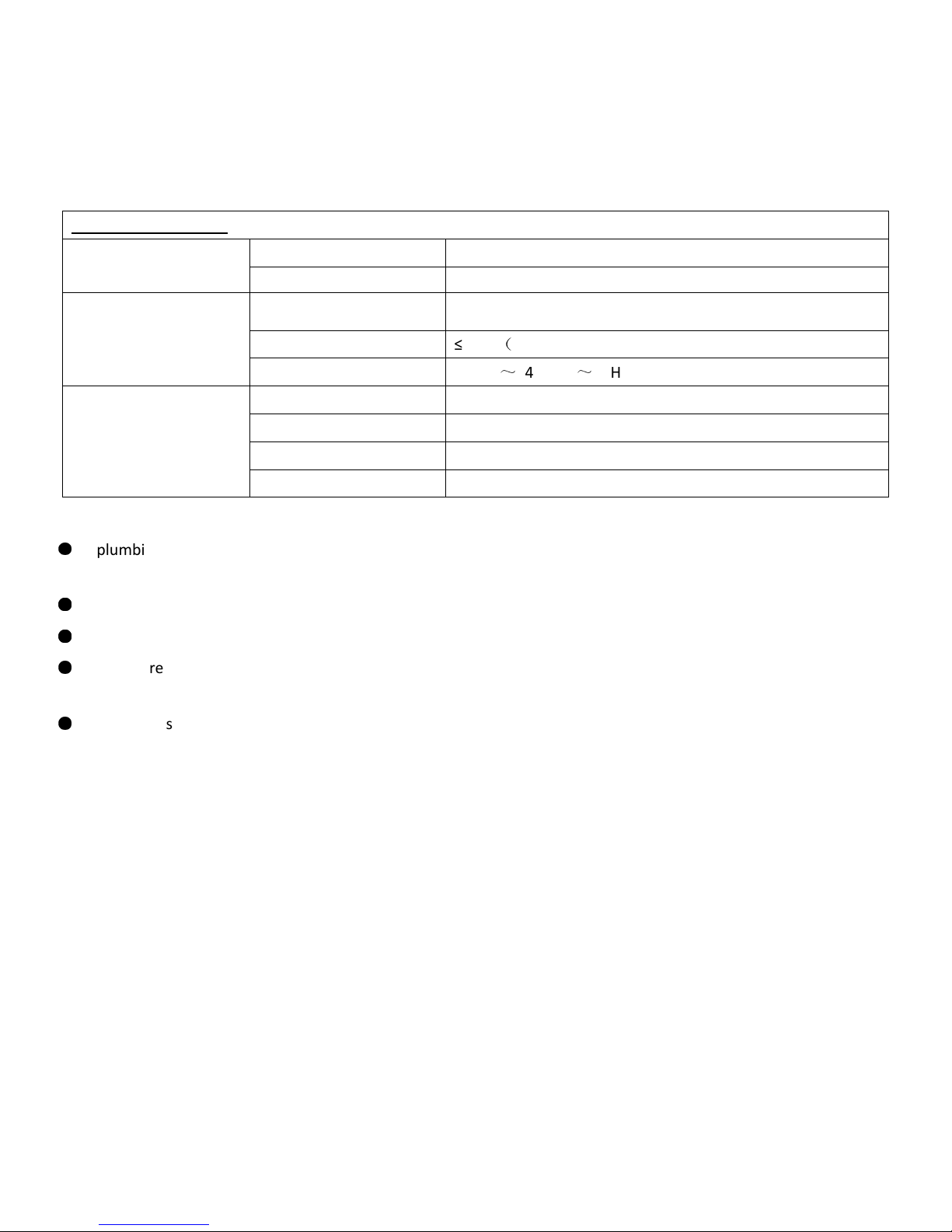
1. Control Valve
2. Resin Tank
Distributor
Tube Inside
the Tank
5. Brine Tank Assembly
3. Parts Bags
Upper
Distributor
4
. Owner's Manual Zip bag
1. Manual(s)
2. Hose clamps
3. Lubricant
This softening system will operate at maximum efficiency when the following conditions are considered:
Operating Conditions:
Working Conditions
Working pressure 21psi to 120psi
Water temperature
40 °F - 120 °F (5°C - 50°C)
Working Environment
Environment
temperature
40 °F - 120 °F (5°C - 50°C)
Relative humidity
(
≤ 95% When temperature is 25°C/77°F
Power source AC100~240V/50~60Hz
Inlet Water Quality
Water turbidity Down-flow Regeneration < 5FTU
Water hardness 1 grain per gallon (gpg) = 17.1 parts per million (ppm)
Chlorine
< 0.1ppm
Iron2+ < 0.3ppm
●
●
●
●
●
All plumbing and electrical work should be performed by an accredited professional to ensure all local, state,
and municipal guidelines are met.
Do not use the control valve with water that is unsafe or of unknown quality.
Do not use the brine tube, injector body, or other connectors on the valve as a handle to carry the system.
●
Ensure there is salt in the brine tank at all times when this valve is used for softening. The brine tank should contain clean
water softening salt only, at least 99.5% pure. Do not use small grain salt.
●
When there is moderate to high turbidity, a filter should be installed before the water softening system on the inlet side.
If the water pressure exceeds 80 psi, installing a pressure reducing valve
recommended. If the water pressure is under 21psi, a booster pump must be installed before the water inlet.
Operating Conditions
4
a. Bypass valve
b. Control Valve
c. Clear tubing
d. Lubricant
e. PVC tubing
f. Upper distributor
g. Brine valve
h. Brine well
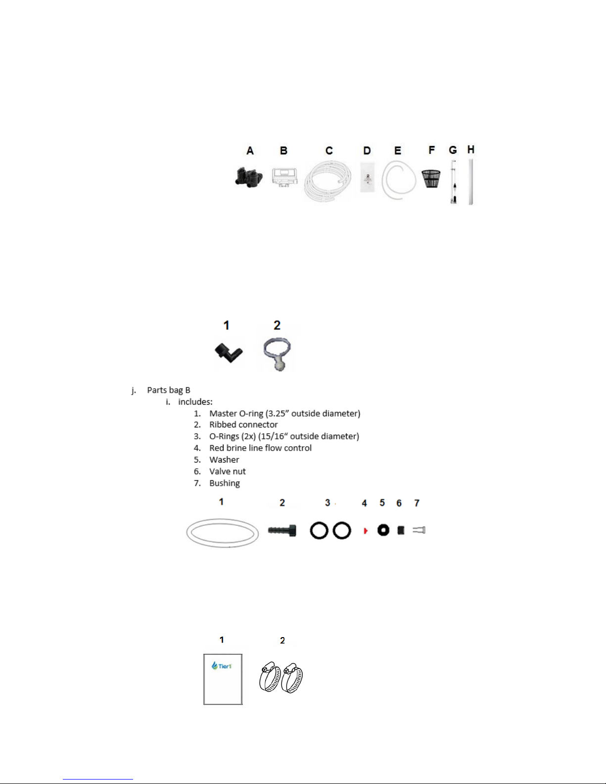
i. Parts bag A
i. Includes:
1. Brine well overflow elbow
2. Brine well mount
k. Instruction manual(s) zip lock packet
i. Includes
1. 165 Series owner’s manual
2. Hose clamp (2x)
ASSEMBLY INSTRUCTIONS
Locate the following parts:
1. Brine Tank – inside the brine tank you will find:
5
ASSEMBLY INSTRUCTIONS
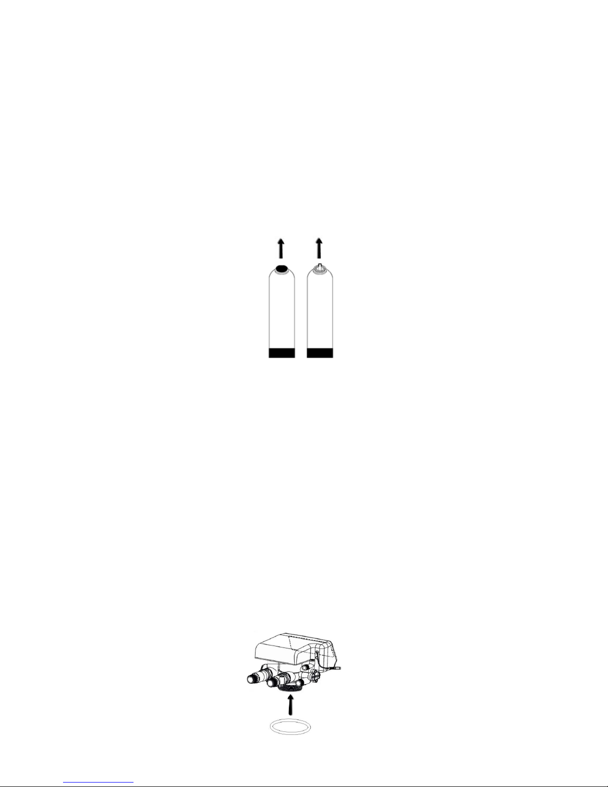
1. Resin Tank - the tank will have a temporary shipping cap, a master O-Ring, and a piece
of tape covering the riser tube. The cap, master O-Ring (another is supplied) and the tape
must be removed and discarded prior to attaching control valve and the upper distributor.
This water softener includes regular control valve connections and a bypass valve connection;
therefore, a set of installation components has been included for each method of installation.
As such, following installation, the installer will be left with an “extra set” of installation
components (animated connectors, brine line flow control, master O-Ring, washers).
2. Read the complete installation guide
3. Unpack the Tier1 WS-165-150 and ensure all parts pictured and listed above are present. such
as tubing, are necessary Rotate the shutoff valve at the main water line to the OFF position
4. Shut off power supply to water heater – only if you will be draining the tank
5. Open the highest and lowest water faucets in your home (drainage and pressure allowance)
6. Ensure you are aware of local laws and codes regarding the installation, use, and maintenance
of water softeners
7. Begin assembly
Assembling the shipped components:
STEP 1: Attaching the Control Valve to the Resin Tank
A. Lightly coat the master O-ring, from Parts bag B, with silicone grease – insert into bottom of
control valve, as shown below
6
 Loading...