

Tier1 165 Series Owner's Manual

165 Series
Water Softener

2
Table of Contents
3
4
5
7
8
9
12
READ THIS MANUAL FIRST
HOW YOUR WATER CONDITIONER WORKS
UNPACKING / INSPECTION OF TWIN TANK MODEL
INSPECTING AND HANDLING
OPERATING CONDITIONS
STARTUP INSTRUCTIONS
MASTER PROGRAMMING

READ THIS MANUAL FIRST
s Read this manual thoroughly to become familiar with the device and its capabilities before installing or operating your Water Softener. Failure to follow instructions in this
manual could result in personal injury or property damage. This manual will also help you to get the most out of your Softener.
s This system and its installation must comply with state and local regulations. Check with your local public works department for plumbing and sanitation codes. In the
event the codes conflict with any content in this manual the local codes should be followed. For installations in Massachusetts, Massachusetts Plumbing Code 248 CMR
shall be adhered to. Consult your licensed plumber for installation of this system.
s Do not use this water Softener on hot water supplies.
s Do not install this unit where it may be exposed to wet weather, direct sunlight, or temperatures outside of the range specified above.
s Avoid pinched o-rings during installation by applying.
s Softeners are commonly exposed to high levels of iron, manganese, sulfur, and sediments. Damage to pistons, seals, and or spacers within the control valve are not
covered in this warranty due to the harsh environment.
s It is recommended to regularly inspect and service the control valve on an annual basis.
s Do not use water that is microbiologically unsafe without adequate disinfection before or after this system.
s This publication is based on information available when approved for printing. Continuing design refinement could cause changes that may not be included in this
publication. Tier1™ reserves the right to change the specifications referred to in this literature at any time, without prior notice.
Safety Messages
Watch for the following safety messages in this manual:
NOTE: used to emphasize installation, operation or maintenance information which is important but does not
present a hazard.
Example: NOTE:
Check and comply with you state and local codes. You must follow these guidelines.
CAUTION: used when failure to follow directions could result in damage to equipment or property.
Example:
CAUTION! Disassembly while under pressure can result in flooding.
WARNING: used to indicate a hazard which could cause injury or death if ignored.
Example:
WARNING! ELECTRICAL SHOCK HAZARD! UNPLUG THE UNIT BEFORE REMOVING THE COVER OR ACCESSING
ANY INTERNAL CONTROL PARTS
3
NOTE: Do not remove or destroy the serial number. It must be referenced on
request for warranty repair or replacement

HOW YOUR WATER CONDITIONER WORKS
Why Water Gets Hard And How It Is Softened
All of the fresh water in the world originally falls as rain, snow, or sleet. Surface water is drawn upward by the sun, forming clouds. Then, nearly pure and soft as it starts to fall,
it begins to collect impurities as it passes through smog and dust-laden atmosphere. And as it seeps through soil and rocks it gathers hardness, rust, acid, unpleasant tastes and
odors.
Water hardness is caused primarily by limestone dissolved from the earth by rainwater. Because of this, in earlier times people who wanted soft water collected rainwater from
roofs in rain barrels and cisterns before it picked up hardness from the earth.
Some localities have corrosive water. A softener cannot correct this problem and so its printed warranty disclaims liability for corrosion of plumbing lines, fixtures or appliances.
Iron is a common water problem. The chemical/physical nature of iron found in natural water supplies is exhibited in four general types:
1. Dissolved Iron—Also called ferrous or “clear water” iron. This type of iron can be removed from the water by the same ion exchange principle that removes the
hardness elements, calcium and magnesium. Dissolved iron is soluble in water and is detected by taking a sample of the water to be treated in a clear glass. The
water in the glass is initially clear, but on standing exposed to the air, it may gradually turn cloudy or colored as it oxidizes.
2. Particulate Iron—Also called ferric or colloidal iron. This type of iron is an undissolved particle of iron. A softener will remove larger particles, but they may not be
washed out in regeneration effectively and will eventually foul the ion exchange resin. A filtering treatment will be required to remove this type of iron.
3. Organic Bound Iron—This type of iron is strongly attached to an organic compound in the water. The ion exchange process alone cannot break this attachment
and the softener will not remove this type of iron.
4. Bacterial Iron—This type of iron is protected inside a bacteria cell. Like the organic bound iron, it is not removed bya water softener.
When using a softener to remove both hardness and dissolved iron it is important that it regenerates more frequently than ordinarily would be calculated for hardness removal
alone. Although many factors and formulas have been used to determine this frequency, it is recommended that the softener be regenerated when it has reached 50–75% of the
calculated hardness alone capacity. This will minimize the potential for bed fouling.
If you are operating a water softener on clear water iron, regular resin bed cleaning is needed to keep the bed from coating with iron. Even when operating a softener on water
with less than the maximum of dissolved iron, regular cleanings should be performed. Clean every six months or more often if iron appears in your conditioned water supply. Use
resin bed cleaning compounds carefully following the directions on the container.
CAUTION! Do not use where the water is microbiologically unsafe or with water of unknown quality
without adequate disinfection before or after the unit.
4

5
Be sure to check the entire unit for any shipping damage or parts loss. Also note damage to the shipping cartons. Contact the transportation company for all damage and loss
claims. The manufacturer is not responsible for damages in transit.
Small parts, needed to install the Softener, are in a parts box. To avoid loss of the small parts, keep them in the parts bag until you are ready to use them.
What is included in the box?
For Model 15, you will expect the following:
1. Control Valve
2. Tank
3. Parts Box
4. Owners Manual
5. Brine Tank Assembly
UNPACKING / INSPECTION OF TWIN TANK MODEL
1. Control Valve
2. Tank
Distributor
Tube Inside
the Tank
Media Inside
the Tank.
Media Type
will depend
on what
models were
purchased
Brine Tank
(Round or
Square)
Brine Tank
Tubing
Brine Well/
Safety Float
Brine Tank Lid
Grid (Round or Square)
Grid Legs (3 for
Round and 4 for
Square)
5. Brine Tank Assembly (Round Brine Tank Shown))
3. Parts Box
2X 1”
Straight
Adapter
Bypass Tool
2 X 3/4”
Elbow
Adapter
Transformer
Grease
Packet
Upper Basket
6
3. Attaching Bypass to Valve (If required in case of replacing the control valve. The new
control valve comes with bypass attached)
Make sure the bypass is attached well to the control valve. Connect the straight or elbow connectors to the bypass with red clips. Connect the inlet and
outlet of the water Softener to the plumbing of the house. The control valve must not be submitted to temperatures above 43°C
(110°F). When sweat fittings are used, to avoid damaging the control valve, solder the threaded copper adapters to the copper pipe and then, using
Teflon tape, screw the assembly into the bypass valve.
Do not use pipe thread compound as it may attack the material in the valve body.
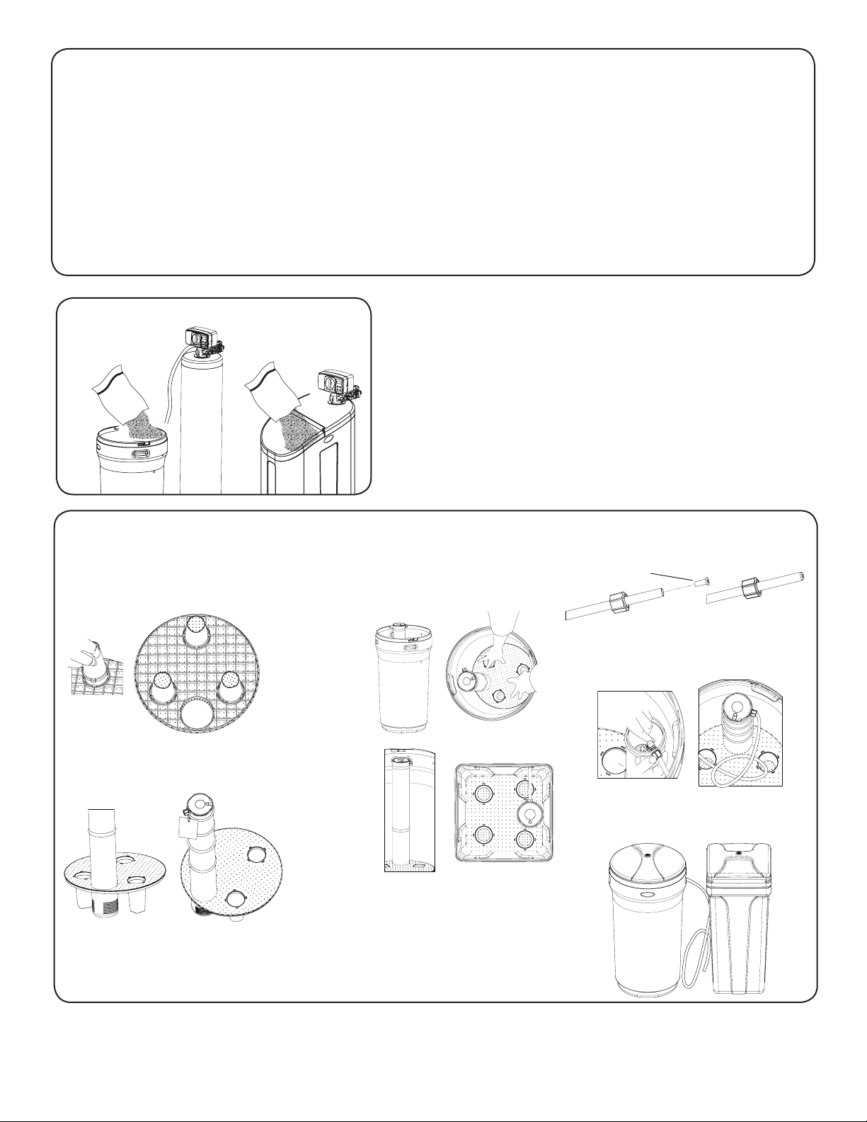
5. Assembling Brine Tank
a) Attach the three brine grid legs to grid plate. The
legs will snap on to the tabs of the salt plate making
a “click” sound. For square brine tank there are four
legs.)
c)
Drop the brine grid with brine well inside the
brine tank such that the nut tting faces the
hole on the brine tank. Then press the grid
evenly inside the brine tank until the brine grid
legs touches the bottom of the brine tank.
b)
Insert the brine well assembly inside the grid
plate as well below.
d)
Take the brine tube and insert the nut and plastic sleeve as
shown below.
e)
Insert the tube in the oat assembly elbow and hand tighten
the nut. In many cases the brine line already come installed
from the factory. Leave the other end of the brine line tube
inside the brine tank
f)
For installation of brine tank at the installation site, pull the
other end of the brine tube from the hole on the brine tank.
The completed assembly is shown below.
The hole in
the brine tank
should line up
with the brine
line as shown
for round and
square brine
tank.
IMPORTANT:
IN ROUND
BRINE TANK, IT
IS IMPORTANT
TO ALIGN THE
HANDLE TO
THE BRINE
WELL AS
SHOWN
Insert Sleeve
4 Add Salt to the brine tank/cabinet
 Loading...