


WiFiScope WS6
User manual
USB
Network
WiFi
Battery power
TiePie engineering

ATTENTION!
Measuring directly on the line voltage can be very dangerous.
The outside of the BNC connectors at the WiFiScope WS6 are connected with
the ground of the computer. Use a good isolation transformer or a differential
probe when measuring at the line voltage or at grounded power supplies! A
short-circuit current will flow if the ground of the WiFiScope WS6 is connected
to a positive voltage. This short-circuit current can damage both the WiFiScope
WS6 and the computer.
Copyright ©2019 TiePie engineering.
All rights reserved.
Revision 2.26, November 2019
Despite the care taken for the compilation of this user manual, TiePie engineering can not be held responsible for any
damage resulting from errors that may appear in this manual.

Contents
1 Welcome 1
2 Safety 3
3 Declaration of conformity 5
4 Introduction 7
4.1 Sampling . . . . . . . . . . . . . . . . . . . . . . . . . . . . . . . . 9
4.2 Sampling rate . . . . . . . . . . . . . . . . . . . . . . . . . . . . . 10
4.2.1 Aliasing . . . . . . . . . . . . . . . . . . . . . . . . . . . . 10
4.3 Digitizing . . . . . . . . . . . . . . . . . . . . . . . . . . . . . . . . 12
4.4 Signal coupling . . . . . . . . . . . . . . . . . . . . . . . . . . . . 12
4.5 Probe compensation . . . . . . . . . . . . . . . . . . . . . . . . . 13
5 Driver installation 15
5.1 Introduction . . . . . . . . . . . . . . . . . . . . . . . . . . . . . . 15
5.2 Where to find the driver setup . . . . . . . . . . . . . . . . . . . . 15
5.3 Executing the installation utility . . . . . . . . . . . . . . . . . . . 15
6 Hardware installation 19
6.1 Power the instrument . . . . . . . . . . . . . . . . . . . . . . . . 19
6.1.1 Charging the battery . . . . . . . . . . . . . . . . . . . . 20
6.1.2 Long term storage . . . . . . . . . . . . . . . . . . . . . 20
6.2 Instrument operation mode . . . . . . . . . . . . . . . . . . . . . 21
6.3 Connect via LAN . . . . . . . . . . . . . . . . . . . . . . . . . . . . 22
6.4 Connect via WiFi . . . . . . . . . . . . . . . . . . . . . . . . . . . . 23
6.4.1 The computer/laptop has WiFi . . . . . . . . . . . . . . . 23
6.4.2 The computer/laptop has NO WiFi . . . . . . . . . . . . 24
6.5 Connect via USB . . . . . . . . . . . . . . . . . . . . . . . . . . . . 26
6.5.1 Plug into a different USB port . . . . . . . . . . . . . . . 26
6.6 Operating conditions . . . . . . . . . . . . . . . . . . . . . . . . . 26
7 Combining instruments 27
Contents I

8 Front panel 29
8.1 Channel input connectors . . . . . . . . . . . . . . . . . . . . . . 29
8.2 Power/Mode button . . . . . . . . . . . . . . . . . . . . . . . . . 29
8.3 Status indicators . . . . . . . . . . . . . . . . . . . . . . . . . . . 29
8.3.1 Status . . . . . . . . . . . . . . . . . . . . . . . . . . . . 29
8.3.2 LAN . . . . . . . . . . . . . . . . . . . . . . . . . . . . . . 29
8.3.3 WiFi . . . . . . . . . . . . . . . . . . . . . . . . . . . . . . 30
8.3.4 USB . . . . . . . . . . . . . . . . . . . . . . . . . . . . . . 30
8.3.5 Batt . . . . . . . . . . . . . . . . . . . . . . . . . . . . . . 30
9 Rear panel 31
9.1 Power . . . . . . . . . . . . . . . . . . . . . . . . . . . . . . . . . 31
9.1.1 Power adapter . . . . . . . . . . . . . . . . . . . . . . . . 32
9.2 USB . . . . . . . . . . . . . . . . . . . . . . . . . . . . . . . . . . . 32
9.3 LAN . . . . . . . . . . . . . . . . . . . . . . . . . . . . . . . . . . . 32
9.4 Extension Connector . . . . . . . . . . . . . . . . . . . . . . . . . 33
9.5 CMI . . . . . . . . . . . . . . . . . . . . . . . . . . . . . . . . . . . 33
9.6 Ventilation slots . . . . . . . . . . . . . . . . . . . . . . . . . . . . 34
10 Specifications 35
10.1 Acquisition system . . . . . . . . . . . . . . . . . . . . . . . . . . 35
10.2 Acquisition system (continued) . . . . . . . . . . . . . . . . . . . 36
10.3 Trigger system . . . . . . . . . . . . . . . . . . . . . . . . . . . . . 37
10.4 Power . . . . . . . . . . . . . . . . . . . . . . . . . . . . . . . . . 37
10.5 Multi-instrument synchronization . . . . . . . . . . . . . . . . . . 37
10.6 Probe calibration . . . . . . . . . . . . . . . . . . . . . . . . . . . 38
10.7 Physical . . . . . . . . . . . . . . . . . . . . . . . . . . . . . . . . . 38
10.8 I/O connectors . . . . . . . . . . . . . . . . . . . . . . . . . . . . . 38
10.9 Interface . . . . . . . . . . . . . . . . . . . . . . . . . . . . . . . . 38
10.10 System requirements . . . . . . . . . . . . . . . . . . . . . . . . . 38
10.11 Environmental conditions . . . . . . . . . . . . . . . . . . . . . . 38
10.12 Certifications and Compliances . . . . . . . . . . . . . . . . . . . 39
10.13 Probes . . . . . . . . . . . . . . . . . . . . . . . . . . . . . . . . . 39
10.14 Package contents . . . . . . . . . . . . . . . . . . . . . . . . . . . 39
10.15 Warranty . . . . . . . . . . . . . . . . . . . . . . . . . . . . . . . . 39
II

Welcome
1
Wireless measuring has now become a reality with the WiFiScope WS6. If a large
distance needs to be bridged between the measuring instrument and the PC, the
WiFiScope WS6 is the solution for this. Fast measurements and high speed data
acquisition are now possible wherever the WiFiScope WS6 is located in the world.
• Because the WiFiScope WS6 is battery-powered, it can be used stand-alone
for a long time.
• For measurements in hazardous situations or places where it is not acces-
sible to people for long, the WiFiScope WS6 offers the solution.
• A connection via WiFi or Network (LAN or WAN with possibly POE) gives the
user the possibility to place the measuring instrument where this was previously not possible.
• Collecting and viewing measurement data from different locations on a PC /
Laptop is now a possibility because the software supports more WiFiScopes
at the same time.
• With the very extensive software package, most measurements can be per-
formed.
• A large library of presets is available so that a novice user can immediately
perform advanced measurements with a few mouse clicks.
• The WiFiScope WS6 has 4 input channels with a maximum sampling rate of
1 GSa/s and a bandwidth of 250 MHz.
• With a WiFi connection, the WiFiScope WS6 is no longer directly connected
to the PC or laptop and short circuits are excluded, this eliminates the fear
that something will happen to the PC or Laptop.
• A big advantage of the WiFiScopes is that no ground loops can occur. In
traditional measurement systems, ground loops give many problems, resulting in unreliable measurement results. With the WiFiScope, because of
the absence of ground loops, long distance remote measurements are possible without the results being influenced by ground loops. Also on short
distances the absence of ground loops is important for performing reliable
measurements. The WiFiScope prevents ground loops from forming so that
the measurement speed and resolution are not affected and the measurements remain reliable.
• Integrating the WiFiScope WS6 in your own software environment is sup-
ported by an API with examples so that the WiFiScope WS6 can be widely
used
• Thanks to a very good hardware structure and advanced software drivers,
the WiFiScope WS6 is suitable for high speed data acquisition up to speeds
of 5 MSa/s and measurements up to 1 GSa/s with a record length of 256
MSamples of memory per channel with a resolution of 12 to 16 bit.
Welcome 1

2 Chapter 1

Safety
2
When working with electricity, no instrument can guarantee complete safety.
It is the responsibility of the person who works with the instrument to operate it in a safe way. Maximum security is achieved by selecting the proper
instruments and following safe working procedures. Safe working tips are
given below:
• Always work according (local) regulations.
• Work on installations with voltages higher than 25 VACor 60 VDCshould only
be performed by qualified personnel.
• Avoid working alone.
• Observe all indications on the WiFiScope WS6 before connecting any wiring
• Check the probes/test leads for damages. Do not use them if they are dam-
aged
• Take care when measuring at voltages higher than 25 VACor 60 VDC.
• Do not operate the equipment in an explosive atmosphere or in the pres-
ence of flammable gases or fumes.
• Do not use the equipment if it does not operate properly. Have the equip-
ment inspected by qualified service personal. If necessary, return the equipment to TiePie engineering for service and repair to ensure that safety features are maintained.
• Measuring directly on the line voltage can be very dangerous. The out-
side of the BNC connectors at the WiFiScope WS6 are connected with the
ground of the computer. Use a good isolation transformer or a differential
probe when measuring at the line voltage or at grounded power supplies!
A short-circuit current will flow if the ground of the WiFiScope WS6 is connected to a positive voltage. This short-circuit current can damage both the
WiFiScope WS6 and the computer.
Safety 3


Declaration of conformity
TiePie engineering
Koperslagersstraat 37
8601 WL Sneek
The Netherlands
EC Declaration of conformity
We declare, on our own responsibility, that the product
WiFiScope WS6-1000(XM/E/S)
WiFiScope WS6-500(XM/S)
WiFiScope WS6-200(XM/S)
for which this declaration is valid, is in compliance with
EC directive 2011/65/EU (the RoHS directive)
including amendement 2015/863,
and with
EN 55011:2009/A1:2010 IEC 61000-6-1/EN 61000-6-1:2007
EN 55022:2006/A1:2007 IEC 61000-6-3/EN 61000-6-3:2007
according the conditions of the EMC standard 2004/108/EC,
3
also with
Canada: ICES-001:2004 Australia/New Zealand: AS/NZS
and
IEC 61010-1:2001/EN USA: UL61010-1: 2004
and is categorized as CAT I 30 Vrms, 42 Vpk, 60 Vdc
Sneek, 15-9-2019
ir. A.P.W.M. Poelsma
Declaration of conformity 5

FCC statement
FCC 15.119
This device complies with Part 15 of FCC Rules. Operation is Subject to following
two conditions:
1. This device may not cause harmful interference, and
2. This device must accept any interference received including interference
that cause undesired operation.
FCC 15.105
This equipment has been tested and found to comply within the limits for a Class
B digital device, pursuant to part 15 of the FCC Rules. These limits are designed
to provide reasonable protection against harmful interference in a residential installation. This equipment generates, uses, and can radiate radio frequency energy
and, if not installed and used in accordance with the instructions, may cause harmful interference to radio communications. However, there is no guarantee that interference will not occur in a particular installation. If this equipment does cause
harmful interference to radio or television reception, which can be determined by
turning the equipment off and on, the user is encouraged to try to correct the
interference by one or more of the following measures:
• Reorient or relocate the receiving antenna
• Increase the separation between the equipment and receiver
• Connect the equipment into an outlet on a different circuit from that to
which the receiver is connected.
• Consult the dealer or an experienced radio/TV technician for help.
Any changes or modifications not expressly approved by TiePie engineering can
void the authority to operate equipment.
This equipment complies with FCC radiation exposure limits set forth for an uncontrolled environment. This equipment should be installed and operated with
minimum distance of 20cm between the radiator and your body
Environmental considerations
This section provides information about the environmental impact of the WiFiScope WS6.
End-of-life handling
Production of the WiFiScope WS6 required the extraction and use of
natural resources. The equipment may contain substances that could
be harmful to the environment or human health if improperly handled
at the WiFiScope WS6’s end of life.
In order to avoid release of such substances into the environment and to reduce
the use of natural resources, recycle the WiFiScope WS6 in an appropriate system
that will ensure that most of the materials are reused or recycled appropriately.
The shown symbol indicates that the WiFiScope WS6 complies with the European
Union’s requirements according to Directive 2002/96/EC on waste electrical and
electronic equipment (WEEE).
6 Chapter 3

Introduction
4
Before using the WiFiScope WS6 first read chapter 2 about safety.
Many technicians investigate electrical signals. Though the measurement may not
be electrical, the physical variable is often converted to an electrical signal, with
a special transducer. Common transducers are accelerometers, pressure probes,
current clamps and temperature probes. The advantages of converting the physical parameters to electrical signals are large, since many instruments for examining electrical signals are available.
The WiFiScope WS6 is a portable four channel measuring instrument with single
ended inputs. It can be connected to the computer via USB, wired ethernet and
WiFi. When used via WiFi, the WiFiScope WS6 can be connected to an existing WiFi
network or can act as access point to create its own WiFi network.
The WiFiScope WS6 is equipped with a built-in battery for wireless operation, but
can also be powered by an external power supply (incluced in the package) or via
the USB interface.
It is available in several models with different maximum sampling rates. The native
resolutions are 8, 12 and 14 bits and a user selectable resolution of 16 bits is
available too, with adjusted maximum sampling rates:
Measuring Model
Resolution Channels WS6-1000 WS6-500 WS6-200
1 ch 1 GSa/s 500 MSa/s 200 MSa/s
8 bit
12 bit
14 bit 1 to 4 ch 100 MSa/s 50 MSa/s 20 MSa/s
16 bit 1 to 4 ch 6.25 MSa/s 3.125 MSa/s 1.25 MSa/s
2 ch 500 MSa/s 200 MSa/s 100 MSa/s
3 or 4 ch 200 MSa/s 100 MSa/s 50 MSa/s
1 ch 500 MSa/s 200 MSa/s 100 MSa/s
2 ch 200 MSa/s 100 MSa/s 50 MSa/s
3 or 4 ch 100 MSa/s 50 MSa/s 20 MSa/s
Table 4.1: Maximum sampling rates
Introduction 7

The WiFiScope WS6 supports high speed continuous streaming measurements.
The maximum streaming rates when connected to a USB 3.0 port are:
Measuring Model
Resolution Channels WS6-1000 WS6-500 WS6-200
1
2
3
2
3
4
2
3
4
40 MSa/s
20 MSa/s
10 MSa/s
20 MSa/s
10 MSa/s
5 MSa/s
20 MSa/s
10 MSa/s
5 MSa/s
8 bit
12 bit
14 bit
1 ch 200 MSa/s1100 MSa/s
2 ch 100 MSa/s
3 or 4 ch 50 MSa/s
1 ch 100 MSa/s
2 ch 50 MSa/s
2
3
2
3
50 MSa/s
25 MSa/s
50 MSa/s
25 MSa/s
3 or 4 ch 25 MSa/s412.5 MSa/s
1 ch 100 MSa/s
2 ch 50 MSa/s
2
3
50 MSa/s
25 MSa/s
3 or 4 ch 25 MSa/s412.5 MSa/s
16 bit 1 to 4 ch 6.25 MSa/s53.125 MSa/s 1.25 MSa/s
Table 4.2: Maximum streaming rates
1
≤ 40 MSa/s when connected to USB 2.0
2
≤ 20 MSa/s when connected to USB 2.0
3
≤ 10 MSa/s when connected to USB 2.0
4
≤ 5 MSa/s when connected to USB 2.0
5
≤ 3.125 MSa/s when connected to USB 2.0, measuring 3 or 4 channels
These maximum streaming rates are only achieved when using the WiFiScope WS6
via its USB interface. When used as wired network instrument, maximum streaming rates may be lower, depending on network speed and load. When used via WiFi,
maximum streaming rates will be lower and will depend on WiFi signal strength,
distance to access point and network load.
The WiFiScope WS6 is available with two memory configurations, these are:
Resolution Channels Standard
8 bit
12, 14, 16 bit
When used as a (WiFi) network instrument, maximum record lengths are limited.
8 Chapter 4
Measuring Model
with XM option
via USB via network
1 ch 1 MSa 256 MSa 64 MSa
2 ch 512 KSa 128 MSa 32 MSa
3 or 4 ch 256 KSa 64 MSa 16 MSa
1 ch 512 KSa 128 MSa 32 MSa
2 ch 256 KSa 64 MSa 16 MSa
3 or 4 ch 128 KSa 32 MSa 8 MSa
Table 4.3: Maximum record lengths per channel

Optionally available for the WiFiScope WS6 is SureConnect connection
test. SureConnect connection test tells you immediately whether your
test probe or clip actually makes electrical contact or not. No more doubt whether
your probe doesn’t make contact or there really is no signal. This is useful when
surfaces are oxidized and your probe cannot get a good electrical contact. Simply
activate the SureConnect and you know whether there is contact or not. Also when
back probing connectors in confined places, SureConnect immediately shows whether
the probes make contact or not.
Models of the WiFiScope WS6 with SureConnect come with resistance
measurement on all channels. Resistances up to 2 MOhm can be measured directly. Resistance can be shown in meter displays and can also be plotted
versus time in a graph, creating an Ohm scope.
With the accompanying software the WiFiScope WS6 can be used as an oscilloscope, a spectrum analyzer, a true RMS voltmeter or a transient recorder. All instruments measure by sampling the input signals, digitizing the values, process
them, save them and display them.
4.1 Sampling
When sampling the input signal, samples are taken at fixed intervals. At these intervals, the size of the input signal is converted to a number. The accuracy of this
number depends on the resolution of the instrument. The higher the resolution,
the smaller the voltage steps in which the input range of the instrument is divided.
The acquired numbers can be used for various purposes, e.g. to create a graph.
Figure 4.1: Sampling
The sine wave in figure 4.1 is sampled at the dot positions. By connecting the
adjacent samples, the original signal can be reconstructed from the samples. You
can see the result in figure 4.2.
Introduction 9

4.2 Sampling rate
The rate at which the samples are taken is called the sampling rate, the number
of samples per second. A higher sampling rate corresponds to a shorter interval
between the samples. As is visible in figure 4.3, with a higher sampling rate, the
original signal can be reconstructed much better from the measured samples.
The sampling rate must be higher than 2 times the highest frequency in the input
signal. This is called the Nyquist frequency. Theoretically it is possible to reconstruct the input signal with more than 2 samples per period. In practice, 10 to
20 samples per period are recommended to be able to examine the signal thoroughly.
4.2.1 Aliasing
When sampling an analog signal with a certain sampling rate, signals appear in the
output with frequencies equal to the sum and difference of the signal frequency
and multiples of the sampling rate. For example, when the sampling rate is 1000
Sa/s and the signal frequency is 1250 Hz, the following signal frequencies will be
present in the output data:
Figure 4.2: ”connecting” the samples
Figure 4.3: The effect of the sampling rate
10 Chapter 4

Multiple of sampling rate 1250 Hz signal -1250 Hz signal
...
-1000 -1000 + 1250 = 250 -1000 - 1250 = -2250
0 0 + 1250 = 1250 0 - 1250 = -1250
1000 1000 + 1250 = 2250 1000 - 1250 = -250
2000 2000 + 1250 = 3250 2000 - 1250 = 750
...
Table 4.4: Aliasing
As stated before, when sampling a signal, only frequencies lower than half the
sampling rate can be reconstructed. In this case the sampling rate is 1000 Sa/s,
so we can we only observe signals with a frequency ranging from 0 to 500 Hz. This
means that from the resulting frequencies in the table, we can only see the 250
Hz signal in the sampled data. This signal is called an alias of the original signal.
If the sampling rate is lower than twice the frequency of the input signal, aliasing
will occur. The following illustration shows what happens.
Figure 4.4: Aliasing
In figure 4.4, the green input signal (top) is a triangular signal with a frequency of
1.25 kHz. The signal is sampled with a rate of 1 kSa/s. The corresponding sampling interval is 1/1000Hz = 1ms. The positions at which the signal is sampled are
depicted with the blue dots. The red dotted signal (bottom) is the result of the reconstruction. The period time of this triangular signal appears to be 4 ms, which
corresponds to an apparent frequency (alias) of 250 Hz (1.25 kHz - 1 kHz).
To avoid aliasing, always start measuring at the highest sampling rate and
lower the sampling rate if required.
Introduction 11

4.3 Digitizing
When digitizing the samples, the voltage at each sample time is converted to a
number. This is done by comparing the voltage with a number of levels. The resulting number is the number corresponding to the level that is closest to the
voltage. The number of levels is determined by the resolution, according to the
following relation: LevelCount = 2
The higher the resolution, the more levels are available and the more accurate
the input signal can be reconstructed. In figure 4.5, the same signal is digitized,
using two different amounts of levels: 16 (4-bit) and 64 (6-bit).
Figure 4.5: The effect of the resolution
The WiFiScope WS6 measures at e.g. 14 bit resolution (214=16384 levels). The
smallest detectable voltage step depends on the input range. This voltage can
be calculated as:
Resolution
.
V oltag eStep = F ullI nputRange/LevelC ount
For example, the 200 mV range ranges from -200 mV to +200 mV, therefore the
full range is 400 mV. This results in a smallest detectable voltage step of 0.400 V /
16384 = 24.41 µV.
4.4 Signal coupling
The WiFiScope WS6 has two different settings for the signal coupling: AC and DC.
In the setting DC, the signal is directly coupled to the input circuit. All signal components available in the input signal will arrive at the input circuit and will be measured.
In the setting AC, a capacitor will be placed between the input connector and the
input circuit. This capacitor will block all DC components of the input signal and
let all AC components pass through. This can be used to remove a large DC component of the input signal, to be able to measure a small AC component at high
resolution.
12 Chapter 4

When measuring DC signals, make sure to set the signal coupling of the
input to DC.
4.5 Probe compensation
The WiFiScope WS6 is shipped with a probe for each input channel. These are
1x/10x selectable passive probes. This means that the input signal is passed through
directly or 10 times attenuated.
When using an oscilloscope probe in 1:1 the setting, the bandwidth of the
probe is only 6 MHz. The full bandwidth of the probe is only obtained in
the 1:10 setting
The x10 attenuation is achieved by means of an attenuation network. This attenuation network has to be adjusted to the oscilloscope input circuitry, to guarantee frequency independency. This is called the low frequency compensation. Each
time a probe is used on an other channel or an other oscilloscope, the probe must
be adjusted.
Therefore the probe is equiped with a setscrew, with which the parallel capacity of
the attenuation network can be altered. To adjust the probe, switch the probe to
the x10 and attach the probe to a 1 kHz square wave signal. Then adjust the probe
for a square front corner on the square wave displayed. See also the following
illustrations.
Figure 4.6: correct
Figure 4.7: under compensated
Introduction 13

Figure 4.8: over compensated
14 Chapter 4

Driver installation
Before connecting the WiFiScope WS6 to the computer via USB, the
drivers need to be installed.
5.1 Introduction
To operate a WiFiScope WS6 via USB, a driver is required to interface between the
measurement software and the instrument. This driver takes care of the low level
communication between the computer and the instrument, through USB. When
the driver is not installed, or an old, no longer compatible version of the driver is
installed, the software will not be able to operate the WiFiScope WS6 properly or
even detect it at all.
The installation of the USB driver is done in a few steps. Firstly, the driver has to
be pre-installed by the driver setup program. This makes sure that all required
files are located where Windows can find them. When the instrument is plugged
in, Windows will detect new hardware and install the required drivers.
5.2 Where to find the driver setup
The driver setup program and measurement software can be found in the download section on TiePie engineering’s website and on the CD-ROM that came with
the instrument. It is recommended to install the latest version of the software and
USB driver from the website. This will guarantee the latest features are included.
5.3 Executing the installation utility
To start the driver installation, execute the downloaded driver setup program, or
the one on the CD-ROM that came with the instrument. The driver install utility
can be used for a first time installation of a driver on a system and also to update
an existing driver.
The screen shots in this description may differ from the ones displayed on your
computer, depending on the Windows version.
5
Driver installation 15

Figure 5.1: Driver install: step 1
When drivers were already installed, the install utility will remove them before installing the new driver. To remove the old driver successfully, it is essential that
the WiFiScope WS6 is disconnected from the computer prior to starting the driver
install utility. When the WiFiScope WS6 is used with an external power supply, this
must be disconnected too.
Clicking ”Install” will remove existing drivers and install the new driver. A remove
entry for the new driver is added to the software applet in the Windows control
panel.
Figure 5.2: Driver install: Copying files
16 Chapter 5

Figure 5.3: Driver install: Finished
Driver installation 17

18 Chapter 5

Hardware installation
Drivers have to be installed before the WiFiScope WS6 is connected to the
computer via USB for the first time. See chapter 5 for more information.
6.1 Power the instrument
The WiFiScope WS6 can be powered in three different ways:
• by its built-in battery
• via an external power adapter, connected to the dedicated power input at
the rear panel
• via the USB interface
When using the WiFiScope WS6 via its battery, no external power is required. The
power consumption of the WiFiScope WS6 depends heavily on the settings of the
instrument, when using higher sampling rates the instrument uses more power.
Also when using larger record lengths, the power consumption increases. It is
therefore not possible to give an exact operating time when running on its battery.
When the battery is charged, the Battery indicator on the front panel will light up
green.
6
When the battery level becomes low, the Battery indicator on the front panel will
light up red.
It is recommended to recharge the battery. When the Battery indicator starts
blinking red, the battery is almost empty and immediate recharging is required.
An indicator in the software will show the battery status and an estimation of the
remaining operating time.
Hardware installation 19

6.1.1 Charging the battery
Charging the battery is done by connecting the external power supply or by connecting the USB. When the battery is charging, the Battery indicator on the front
panel will light up blue.
When connected to USB or external power, the battery will only be charged when
the USB or external power can deliver enough power to operate the instrument
and to charge the battery. When not enough power is available, the battery will
be discharged. This is indicated by a blue blinking Battery indicator on the front
panel of the instrument.
6.1.2 Long term storage
When storing the WiFiScope WS6 for a long time, it is recommended to first charge
the battery to approximately 70 %. Do not store the WiFiScope WS6 for a long time
with an empty battery or 100 % fully charged battery, as this may reduce battery
capacity.
20 Chapter 6

6.2 Instrument operation mode
The WiFiScope WS6 has a USB interface and a network interface, used to connect
to the instrument via LAN or WiFi. The Power/Mode button at the front panel determines if the WiFiScope WS6 operates as USB instrument or as network (LAN
or WiFi) instrument. The light in the Power/Mode button indicates in which mode
the WiFiScope WS6 operates. When it is on, the network interface is enabled and
the instrument operates as newtwork (LAN or WiFi) instrument. When it is off, the
network interface is disabled and the WiFiScope WS6 operates as USB instrument.
Power/Mode button light off: The
WiFiScope WS6 can only be used via
USB
When the network interface of the WiFiScope WS6is disabled, it will go to a low
power state, to save the battery. To enable it again, a short press on the Power/Mode
button is required.
When the WiFiScope WS6 is not connected to external power or USB and is not
used for two days (network interface disabled), the WiFiScope WS6 switches to
”Shipping mode”, where the network interface is consuming no power at all. To
wake up the WiFiScope WS6 from shipping mode, press the Power/Mode button
for 2 seconds. When arriving from the factory, the WiFiScope WS6 will be in shipping mode.
When for some reason the network interface will not disable (the lights remain on),
pressing the Power/Mode button for 3 seconds will force the network interface to
be disabled.
Power/Mode button light on: The
WiFiScope WS6 can only be used via
LAN or Wifi
Hardware installation 21

6.3 Connect via LAN
To use the WiFiScope WS6 via the LAN, connect the WiFiScope WS6 LAN port on
the rear panel to the LAN via a network cable.
The WiFiScope WS6 network interface must be enabled via the Power/Mode button on the front panel of the instrument. While the network interface is initializing,
the Power/Mode button will blink, when the initialization is finished, the Power/Mode
button will light up continuously.
When the LAN cable is connected, the LAN interface will attempt to get an address via DHCP. When that is sucessful, the LAN indicator on the front panel of
the instrument will light up green.
When afer 20 seconds no DHCP is found, the network interface will switch to linklocal mode and use a link-local address. The LAN indicator on the front panel of the
instrument will light up blue to indicate link-local mode. Link-local mode remains
active until the LAN cable is removed and the LAN LED goes off. When the LAN
cable is then reconnected, getting an address via DHCP is attempted again.
In the Multi Channel software, open the Manage instruments dialog and check
Seach instruments in local network.
When searching the network is checked, the WiFiScope WS6 will appear. To connect the software to the WiFiScope WS6 check it and close the dialog with the OK
button.
22 Chapter 6

6.4 Connect via WiFi
There are several different ways to connect the computer to the WiFiScope WS6
via WiFi, depending on whether the computer/laptop has WiFi or not.
6.4.1 The computer/laptop has WiFi
To use the WiFiScope WS6 via Wifi, the network interface must be enabled via
the Power/Mode button on the front panel of the instrument. While the network
interface is initializing, the Power/Mode button will blink, when the initialization is
finished, the Power/Mode button will light continuously.
When the computer does have WiFi, there are two different ways to connect to
the instrument via WiFi.
Connect the WiFiScope WS6 to the local WiFi network
1. In the Multi Channel software open the Manage instruments dialog and
check Seach instruments in local network.
2. Place a check in front of the detected WiFiScope WS6. It may take a few
seconds to discover the instrument.
3. The software will now ask how to connect to the WiFiScope WS6, select Add
WifiScope to the ’WiFi’ network..
4. The connection is now set up, if required, the software will ask for the net-
work password. The setup may take up to 30 seconds.
The WiFiScope WS6 is now connected to the local network via WiFi.
Hardware installation 23

Connect to the WiFiScope WS6 directly using WiFi
1. In the Multi Channel software open the Manage instruments dialog and
check Seach instruments in local network.
2. Place a check in front of the detected WiFiScope WS6. It may take a few
seconds to discover the instrument.
3. If the computer is currently connected to a WiFi network, the software will
ask how to connect to the WiFiScope WS6, select Add WifiScope to the
’WiFi’ network..
4. The connection is now set up, if required, the software will ask for the net-
work password. The setup may take up to 30 seconds.
The WiFiScope WS6 is now setup as Access Point, to create its own WiFi network.
The computer is disconnected from the local Wifi network and connected to the
WiFiScope WS6 WiFi network. The computer will now no longer have internet access and/or access to network locations.
6.4.2 The computer/laptop has NO WiFi
When the computer has no WiFi, the WiFiScope WS6 will have to be connected to
the local network. Therefore, the network interface of the WiFiScope WS6 must be
enabled via the Power/Mode button on the front panel of the instrument. While
the network interface is initializing, the Power/Mode button will blink, when the
initialization is finished, the Power/Mode button will light continuously.
24 Chapter 6
1. Connect the WiFiScope WS6 via a cable to the LAN as shown in the section
Connect via LAN.
2. In the Multi Channel software open the Manage instruments dialog and
check Seach instruments in local network.
3. Place a check in front of the detected WiFiScope WS6. It may take a few
seconds to discover the instrument.
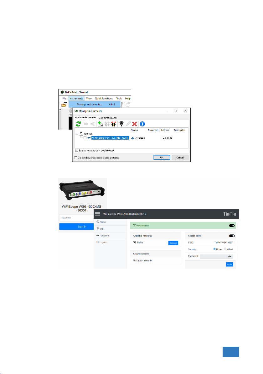
4. Click the WiFi button in the istruments manager to open the WiFiScope WS6
web interface.
5. Login to the web interface (default password = tiepie).
6. In the web interface, connect to the WiFi network using the connect button
(and enter its password if required)
7. When successfully connected, close the web interface and disconnect the
LAN cable.
8. The Multi Channel software will now detect the WiFiScope WS6 via WiFi, this
may take a few seconds.
Hardware installation 25

6.5 Connect via USB
To use the WiFiScope WS6 via USB, connect the WiFiScope WS6 USB port on the
rear panel to the computer via a USB cable.
When using the instrument via USB, the network interface must disabled via the
Power/Mode button on the front panel of the instrument.
When a USB connection is established, this is indicated by a green lit USB indicator
on the front panel of the instrument.
The software can now connect to the WiFiScope WS6 as local instrument.
6.5.1 Plug into a different USB port
When the WiFiScope WS6 is plugged into a different USB port, some Windows versions will treat the WiFiScope WS6 as different hardware and will install the drivers
again for that port. This is controlled by Microsoft Windows and is not caused by
TiePie engineering.
6.6 Operating conditions
The WiFiScope WS6 is ready for use as soon as the software is started. However,
to achieve rated accuracy, allow the instrument to settle for 20 minutes. If the
instrument has been subjected to extreme temperatures, allow additional time
for internal temperatures to stabilize. Because of temperature compensated calibration, the WiFiScope WS6 will settle within specified accuracy regardless of the
surrounding temperature.
26 Chapter 6

Combining instruments
7
When more channels are required than one instrument can offer, multiple instruments can be combined into a larger combined instrument. To combine two or
more instruments, the instruments need to be connected to each other using
special cables.
Combining instruments is only available when the WiFiScope WS6 is connected to the computer via the USB. When used as network instrument
(LAN or WiFi), combining is not possible.
The CMI (Combine Multiple Instruments) interface that is available by default on
the WiFiScope WS6 provides an easy way to couple multiple oscilloscopes to one
combined oscilloscope.
Figure 7.1: CMI diagram
The CMI interface supports automatic recognition of the instrument. The high
speed trigger bus is automatically terminated with the correct impedance and
the high speed sampling bus is automatically configured and terminated at the
beginning and end of the bus. The high speed sampling bus takes care that each
Handyscope is fully synchronized to ensure that even at the highest sampling rate
the instruments operate at the same sample clock (0 ppm clock error!). The connection order when combining multiple instruments is not important. The CMI interface has built-in intelligence to detect the connections and terminate all buses
properly at both ends of the bus. So instruments can be connected to each other
in random order. Placing terminators and determining the proper connection order is not required!
Advantages of the CMI (Combine Multiple Instruments) interface are:
• automatic instrument recognition,
• automatic creation and termination of the high speed trigger bus,
• automatic creation and termination of the high speed sampling bus,
• automatic master/slave setting of the sampling clock bus.
Combining instruments 27

Figure 7.2: CMI connectors
Connecting is done by daisy chaining the CMI connectors of the instruments prior
to starting the software, using special coupling cables (order number TP-C50H).
The software will detect how the instruments are connected to each other and
will automatically terminate the connection bus. The software will combine the
connected instruments to one large instrument. The combined instruments will
sample using the same clock, with a deviation of 0 ppm.
Figure 7.3: 2 WiFiScope WS6s combined
A 20 channel instrument is easily made by connecting five WiFiScope WS6s to each
other.
When combining one or more WiFiScope WS6 s with Handyscope HS5 s and/or
WiFiScope WS5s, the daisy chained CMI bus must begin or end with a WiFiScope
WS6. Additionally, the maximum sampling rate is limited to 100 MSa/s at 14 bit
resolution.
28 Chapter 7

Front panel
Figure 8.1: Front panel
8.1 Channel input connectors
The CH1 – CH4 BNC connectors are the main inputs of the acquisition system. The
outside of the BNC connectors is connected to the ground of the WiFiScope WS6.
Connecting the outside of the BNC connector to a potential other than ground
will result in a short circuit that may damage the device under test, the WiFiScope
WS6 and the computer.
8.2 Power/Mode button
The Power/Mode button is situated at the right of the front of the instrument. It
is used to switch the mode of the WiFiScope WS6 between USB use and LAN or
WiFi use. To use the WiFiScope WS6 via LAN or WiFi, the network interface must
be enabled, by pressing the Power/Mode button. During initializing the network
interface, the Power/Mode button will blink green. When initialization is finished,
the indicator in the button will be lit continuously green.
When using the WiFiScope WS6 via USB, the network interface must be disabled,
by pressing the Power/Mode button again. The light in the button will go off.
8.3 Status indicators
The WiFiScope WS6 has a number of status indicators, which can be lit to indicate
the status of the instrument.
8.3.1 Status
The status light indicates whether the WiFiScope WS6 is being used by software
or is not in use.
8
8.3.2 LAN
When the LAN indicator is lit, the WiFiScope WS6 is connected to a wired network.
• When lit continuously green, the WiFiScope WS6 not being used, it is avail-
able to be opened in software.
• When lit continuously blue, the WiFiScope WS6 is in use, it is already opened
in software.
Front panel 29

8.3.3 WiFi
When the WiFi indicator is lit, the WiFiScope WS6 is connected to the computer
and measuring via a WiFi network. The color indicates how the instrument operates:
8.3.4 USB
When the USB indicator is green, the WiFiScope WS6 is connected to the computer
and measuring via USB.
8.3.5 Batt
The Batt indicator can indicate various different states:
• When lit continuously green, the WiFiScope WS6 has received a network
address via DHCP.
• When lit continuously blue, the WiFiScope WS6 is assigned a link local ad-
dress.
• When blinking green, the WiFiScope WS6 is trying to establish a WiFi con-
nection to an existing network.
• When lit continuously green, the WiFiScope WS6 has established a connec-
tion to an existing WiFi network and has received a network address via
DHCP.
• When lit continuously blue, the WiFiScope WS6 acts as WiFi access point.
Connect the computer via WiFi to the network that the WiFiScope WS6 creates.
• When lit continuously green, the battery is full, while the extenal power is
still connected. When external power is not connected, the battery is being
discharged, its level is higher than 5
• When lit continuously blue, the battery is charging.
• When blinking blue, external power or USB power is connected, but cannot
deliver enough power to charge the battery.
• When lit continuously red, the battery level is below 5 %, charging is recom-
mended.
• When blinking red, the battery level is below 2 %, immediate charging is re-
quired.
30 Chapter 8

Rear panel
Figure 9.1: Rear panel
9.1 Power
The WiFiScope WS6 can be powered by its internal battery, via a dedicated power
input at the rear panel and via the USB interface.
To charge the battery, connect the external power supply. The battery can also be
charged via the USB, but only if the USB can deliver enough power to operate the
instrument and charge the battery. If not enough power for both is available, the
battery will not be charged, but will be used by the instrument and be discharged.
The specifications of the dedicated power connector are:
Pin Dimension Description
Center pin Ø1.3 mm positive
Outside bushing Ø3.5 mm ground
9
Figure 9.2: Power connector
The following minimum and maximum voltages apply to the power inputs:
Minimum 5 VDC/ 2 A
Maximum 12 VDC/ 2 A
Table 9.1: Maximum voltages
Rear panel 31

9.1.1 Power adapter
The WiFiScope WS6 comes with an external 12 VDC2 A power adapter that can be
connected to any mains power net that supplies 100 – 240 VAC, 50 – 60 Hz. The
external power adapter can be connected to the dedicated power connector.
9.2 USB
Figure 9.3: Power adapter
The WiFiScope WS6 is equipped with a USB 3.0 Super speed (5 Gbit/s) interface
with a USB 3 type B Super speed socket. It will also work on a computer with a
USB 2.0 interface, but will then operate at 480 Mbit/s.
9.3 LAN
The WiFiScope WS6 is equipped with a 1 Gbit LAN interface with RJ45 socket.
32 Chapter 9
Figure 9.4: USB connector
Figure 9.5: LAN connector

9.4 Extension Connector
Figure 9.6: Extension connector
A 9 pin female D-sub connector is available at the back of the WiFiScope WS6
containing the following signals:
Pin Description Pin Description Pin Description
1 EXT 1 (LVTTL) 4 reserved 7 NC
2 EXT 2 (LVTTL) 5 reserved 8 Power OUT (see description)
3 Probe Cal 6 GND 9 External Clock in
Table 9.2: Pin description Extension connector
Pins EXT 1 and EXT 2 are equipped with internal 1 kOhm pull-up resistors to 2.5 V.
These pins can simultaneously be used as inputs and outputs. Each pin can be
configured as external digital trigger input for the acquisition system of the WiFiScope WS6.
Pin 3, Probe Cal, has a 1 kHz, -1 V to 1 V square wave signal that can be used to
perform probe frequency compensations.
Pin 8, Power OUT, is 5 VDCand can supply 100 mA and is available when the
Power/Mode button of the WiFiScope WS6 is switched on.
The External Clock In signal must be a 10 MHz ± 1% or a 16.369 MHz ± 1% 2.5 V
TTL signal.
9.5 CMI
The WiFiScope WS6 has two Combine Multiple Instruments interface (CMI) connectors at the rear of the instrument. These connectors are used to combine
multiple instruments to a single combined instrument to perform synchronized
measurements. This requires a TP-C50H coupling cable per two instruments.
Figure 9.7: CMI connector
The CMI connectors use HDMI type C sockets, but are not HDMI compliant.
They can not be used to connect an HDMI device to the WiFiScope WS6.
Rear panel 33

9.6 Ventilation slots
Below the LAN connector and power connector a ventilation slot is located, with
a fan behind it. And below the CMI connectors three smaller ventilation slots are
located.
Figure 9.8: Ventilation slots
Do not block the ventilation slots as this may cause the WiFiScope WS6
becoming too hot.
Do not insert objects in the ventilation slot as this may damage the fan.
34 Chapter 9

Specifications
To achieve rated accuracy, allow the instrument to settle for 20 minutes. When
subjected to extreme temperatures, allow extra time for internal temperatures to
stabilize. Because of temperature compensated calibration, the WiFiScope WS6
will settle within specified accuracy regardless of the surrounding temperature.
10.1 Acquisition system
Number of input channels 4 analog
CH1, CH2, CH3, CH4 BNC
Type Single ended
Resolution 8, 12, 14, 16 bit user selectable
Accuracy 0.25% of full scale ± 1 LSB
Ranges (full scale) ±200 mV
Coupling AC/DC
Impedance 1 MΩ / 20 pF ± 1 %
Maximum voltage 200 V (DC + AC peak <10 kHz)
Bandwidth WS6-1000 WS6-500 WS6-200
-3 dB, at 75 % of full scale 250 MHz 250 MHz 250 MHz
Limit, selectable per channel Off (250 MHz)
AC coupling cut off freq. (-3dB) ±1.5 Hz
SureConnect Optionally available (option S)
Maximum voltage on connection 200 V (DC + AC peak <10 kHz)
Resistance measurement Optionally available (option S)
Ranges 1 kΩ
Accuracy 1%
Response time (to 95%) <10 µs
Maximum sampling rate WS6-1000 WS6-500 WS6-200
8 bit
Measuring 1 channel 1 GSa/s 500 MSa/s 200 MSa/s
Measuring 2 channels 500 MSa/s 200 MSa/s 100 MSa/s
Measuring 3 or 4 channels 200 MSa/s 100 MSa/s 50 MSa/s
12 bit
Measuring 1 channel 500 MSa/s 200 MSa/s 100 MSa/s
Measuring 2 channels 200 MSa/s 100 MSa/s 50 MSa/s
Measuring 3 or 4 channels 100 MSa/s 50 MSa/s 20 MSa/s
14 bit 100 MSa/s 50 MSa/s 20 MSa/s
16 bit 6.25 MSa/s 3.125 MSa/s 1.25 MSa/s
±2 V
±20 V
150 MHz
100 MHz
75 MHz
10 kΩ
100 kΩ
1 MΩ
Off (250 MHz)
150 MHz
100 MHz
75 MHz
±400 mV
±4 V
±40 V
Off (250 MHz)
150 MHz
100 MHz
75 MHz
2 kΩ
20 kΩ
200 kΩ
2 MΩ
10
±800 mV
±8 V
±80 V
Off (100 MHz)
75 MHz
50 MHz
25 MHz
Off (100 MHz)
75 MHz
50 MHz
25 MHz
5 kΩ
50kΩ
500 kΩ
Specifications 35

10.2 Acquisition system (continued)
Maximum streaming rate
8 bit
Measuring 1 channel 200 MSa/s
Measuring 2 channels 100 MSa/s
Measuring 3 or 4 channels 50 MSa/s
12 bit
Measuring 1 channel 100 MSa/s
Measuring 2 channels 50 MSa/s
Measuring 3 or 4 channels 25 MSa/s
14 bit
Measuring 1 channel 100 MSa/s
Measuring 2 channels 50 MSa/s
Measuring 3 or 4 channels 25 MSa/s
16 bit 6.25 MSa/s
Sampling source
Internal TCXO
Accuracy ±0.0001%
Stability ±1 ppm over 0◦C to +55◦C
Time base aging ±1 ppm per year time base aging
External LV-TTL (2.5 V), on Extension connector
Input frequency 10 MHz ±1 %
Memory Standard
8 bit
Measuring 1 channel 1 MS 256 MS 64 MS
Measuring 2 channels 512 KS 128 MS 32 MS
Measuring 3 or 4 channels 256 KS 64 MS 16 MS
12, 14, 16 bit
Measuring 1 channel 512 KS 128 MS 32 MS
Measuring 2 channels 256 KS 64 MS 16 MS
Measuring 3 or 4 channels 128 KS 32 MS 8 MS
67
WS6-1000 WS6-500 WS6-200
1
2
3
2
3
4
2
3
4
5
1
≤ 40 MSa/s when connected to USB 2.0
2
≤ 20 MSa/s when connected to USB 2.0
3
≤ 10 MSa/s when connected to USB 2.0
4
≤ 5 MSa/s when connected to USB 2.0
5
≤ 3.125 MSa/s when connected to USB 2.0, measuring 2 or more chan-
nels
6
On some computers, the highest streaming rates may not be available,
due to computer restrictions.
7
When connected through LAN or WiFi, the maximum streaming rates are
limited and depend on the speed and load of the network
16.369 MHz ±1 %
model
1
100 MSa/s
2
50 MSa/s
3
25 MSa/s
2
50 MSa/s
3
25 MSa/s
4
12.5 MSa/s
2
50 MSa/s
3
25 MSa/s
4
12.5 MSa/s
3.125 MSa/s 1.25 MSa/s
XM option
via USB
40 MSa/s
20 MSa/s
10 MSa/s
20 MSa/s
10 MSa/s
5 MSa/s
20 MSa/s
10 MSa/s
5 MSa/s
XM option
via LAN/Wifi
36 Chapter 10

10.3 Trigger system
System Digital, 2 levels
Source CH1, CH2, CH3, CH4, digital external, OR
Trigger modes Rising edge, falling edge, any edge,
Level adjustment 0 to 100% of full scale
Hysteresis adjustment 0 to 100% of full scale
Resolution 0.024 % (12 bits)/0.006 % (14/16 bits)
Pre trigger 0 to selected record length, 1 sample resolution
Post trigger 0 to selected record length, 1 sample resolution
Trigger hold-off 0 to 64 MSamples, 1 sample resolution
Trigger delay 0 to 16 GSamples, 1 sample resolution
Digital external trigger
Input Extension connector pins 1 and 2
Range 0 to 2.5 V (TTL)
Coupling DC
Jitter ≤ 1 sample
10.4 Power
Power From USB, external input or built-in battery
Consumption 12 VDC, 2 A max
Internal battery Li-ion
Capacity 8000 mAh, 3.7 V
Operating time Strongly depending on instrument setup, ≥ 3 hours
Power adapter External
Input 110 to 240 VAC, 50 to 60 Hz, 500 mA
Output 12 VDC, 2 A
Dimension
Height 57 mm / 2.2”
Width 30 mm / 1.2”
Length 88 mm / 3.4”
Cable length 1.8 m / 70”
Order number TP-UES24LCP-120200SPA
Replaceable mains plugs for EU, US, AU, UK
inside window, outside window,
enter window, exit window,
pulse width
10.5 Multi-instrument synchronization
Combining instruments is only available when all instruments are connected via USB.
When instruments are connected via LAN or WiFi, combining is not availble.
Maximum number of instruments Limited by available number of USB ports
Synchronization accuracy 0 ppm
CMI interface 2x, CMI 1, CMI 2
Required coupling cable TP-C50H Coupling cable CMI
Maximum coupling cable length 50 cm
Specifications 37

10.6 Probe calibration
Output Extension connector pins 3 (signal) and 6 (ground)
Signal Square wave
Level -1 V to 1 V
Frequency 1 kHz
10.7 Physical
Height 44 mm / 1.7”
Length 187 mm / 7.4”
Width 215 mm / 8.5”
Weight 751 g / 26.5 ounce
USB cord length 1.5 m / 59”
10.8 I/O connectors
CH1, CH2, CH3, CH4 BNC
USB USB3 type B Super Speed socket
LAN RJ45 socket
Extension connector D-sub 9 pins female
Power 3.5 mm power socket
CMI connectors 1–2 HDMI type C socket
10.9 Interface
Interface USB 3.0 SuperSpeed (5 Gbit/s)
(USB 2.0 HighSpeed (480 Mbit/s) compatible)
10.10 System requirements
PC I/O connection USB 2.0 or newer
Operating System Windows 10, 32 and 64 bits
10.11 Environmental conditions
Operating
Ambient temperature 20◦C to 25◦C for rated accuracy
Relative humidity 10 to 90% non condensing
Charging
Ambient temperature 0◦C to 35◦C
Relative humidity 10 to 90% non condensing
Storage
Ambient temperature 0◦C to 35◦C
Relative humidity 5 to 95% non condensing
10◦C to 40◦C without specifications
38 Chapter 10

10.12 Certifications and Compliances
CE mark compliance Yes
RoHS Yes
EN 55011:2009/A1:2010 Yes
EN 55022:2006/A1:2007 Yes
IEC 61000-6-1/EN 61000-6-1:2007 Yes
IEC 61000-6-1/EN 61000-6-1:2007 Yes
Canada: ICES-001:2004 Yes
Australia/New Zealand: AS/NZS Yes
10.13 Probes
Model HP-9250
Bandwidth 6 MHz 250 MHz
Rise time 58 ns 1.4 ns
Input impedance 1 MΩ
Input capacitance 47 pF
Compensation range - 10 to 35 pF
Working voltage (DC + AC peak) 300 V CAT I
10.14 Package contents
Instrument WiFiScope WS6
Probes 4 x X1 / X10 switchable, HP-9250
Accessories External power adapter
Software Windows 10
Drivers Windows 10
Manual Quick Start Guide, Instrument manual and software
10.15 Warranty
TiePie engineering instruments are designed, manufactured and tested to provide high reliability. In the unlikely event you experience difficulties, the TiePie engineering instruments are fully warranted for two years.
This warranty includes All parts and labor (excluding probes and/or measure
Optionally available Extension to five year warranty, option W5
X1 X10
oscilloscope impedance
+ oscilloscope capacitance
150 V CAT II
USB cable
network cable
manual
leads and/or batteries)
Warranty on batteries is 6 months.
No charge for return shipping
Long-term 7 year support
Upgrade to the latest software at no charge
10 MΩ
incl. 1 MΩ oscilloscope impedance
17 pF
600 V CAT I
300 V CAT II
Specifications 39

40 Chapter 10

If you have any suggestions and/or remarks regarding this manual, please contact:
TiePie engineering
Koperslagersstraat 37
8601 WL SNEEK
The Netherlands
Tel.: +31 515 415 416
Fax: +31 515 418 819
E-mail: support@tiepie.nl
Site: www.tiepie.com

TiePie engineering WiFiScope WS6 instrument manual revision 2.26, November 2019
 Loading...