

Tien Hsin SFED8400 User Manual
USER’S MANUAL AND INSTRUCTIONS


Index
1. Introduction
2. Drivetrain Parts
3. Tools and Supplies
4. Frame Preparation
4.1.RD Cable Routing
4.2.FD Cable Routing
4.3.Bottom Bracket Mounting
5. Drivetrain Installation
5.1.FD Installation
5.2.RD Installation
5.3.Shifter Installation
5.4.Battery Installation
5.5.Chain Installation
6. Pairing
7. Usage and Adjustments
7.1.Power ON
7.2.Power OFF
7.3.Rear Derailleur Alignment
7.4.Front Derailleur Alignment
7.5.Limit Screw Adjustment
7.6.B-tension Screw Adjustment
8. Battery Diagnostic
8.1.Main Battery
8.2.Shifter Battery
9. Battery Charging
9.1.Shifter Battery Replacement
10. Diagnostics
11. Battery Warning
12. Important Information
1. Introduction
Congratulations on your Full Speed Ahead product. Please read these instructions and follow them for correct
use. Failure to follow the warnings and instructions could result in damage to product not covered under
warranty, damage to bicycle; or cause an accident resulting in injury or death. Since specific tools and
experience are necessary for proper installation, it is recommended that the product be installed by a qualied
bicycle technician. FSA assumes no responsibility for damages or injury related to improperly installed
components.
2. Drivetrain Parts
FSA K-Force WE is an electronic hybrid drivetrain. It is dened as hybrid because is not completely wireless.
Indeed, there are no wires from shifters to derailleurs but the communication between the two derailleurs is
still effectuated using wires.
The different parts of the drivetrain will be explained in this section.
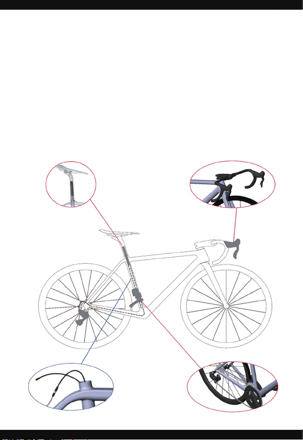
•Main Battery
The main battery is placed into
the seatpost and provides power
to the two derailleurs through
two wires.
•Shifters
Shifters wirelessly communicate
with derailleurs. They have their
own coin cell batteries, located
inside the housing.
•Front and Rear Derailleur
•Wires
Two internally routed wires,
one longer and one shorter,
connect front and rear
derailleurs to the battery.
3. Tools and Supplies
FSA recommends installation of WE Drivetrain to be performed by a highly experienced bicycle mechanic.
The following tools and supplies are needed for correct installation
of FSA WE Drivetrain. See tool list below:
• Hex wrench sizes (1.5 mm, 2 mm, 5 mm)
• Torque wrench (2-14 Nm range)
• Phillips screwdriver size PH2
• FSA cable guide tool
• 11sp compatible chain rivet tool
• Light grease
FSA recommends using the following protective equipment for
your own safety:
• Protective glasses
• Latex or Nitrile gloves
4. Frame Preparation
Before to start assembling the drivetrain you will have to insert the wires for Front Derailleur FD and Rear
Derailleur RD inside your frame. Any frame compatible with DI2 internal wire specication will be compatible
also for WE wire routing.
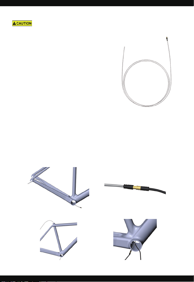
RD Wire Routing
Insert the wire guide tool in the rear chainstay to the BB shell as per picture below
Connect the RD wire to the female plug
of the wire guide tool.
Unplug the wire guide and slide it inside
the seat tube from the BB shell as per
picture below.
Pull the wire guide to thread the RD wire
inside the rear chainstay
Connect the wire to the wire guide tool
and pull up through the seat tube.
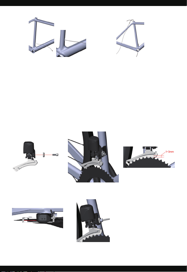
FD Wire Routing
Slide the wire guide tool through the FD
routing hole into the seat tube.
Connect the FD wire and pull up through
the seat tube.
Bottom Bracket and Crankset mounting
For BB and crankset mounting, check the dedicated FSA instructions.
5. Drivetrain Installation
Before assembling the drivetrain, install Front Derailleur (FD) and Rear Derailleur (RD) wires. WE wires are
compatible with industry standard internal wire routing.
FD Installation
1 2 3
Install the front derailleur on frame
braze-on using supplied.
End of sentence in point 1. Snug
the bolt enough to hold derailleur
in position.
Adjust the derailleur height so the
gap between outer cage and large
chainring is 1 to 3 mm. See image
3
4 5
When gap is set, rotate the
derailleur so the cage position is
parallel with the chainrings. See
image 4
When derailleur position is correct,
tighten the derailleur bolt to 5-7
Nm.
 Loading...