

TiEmme GLH110 User Manual

Pag. 1/15
0CAR6IN019124_Manual_GLH110_Rev_0.3
GLH110 Glass Temperature Controller
User Manual
1. MAIN FEATURES
The GLH110 Temperature Controller manages Wood Fireplaces and Boilers, for heating and domestic hot water production, with the
possibility to integrate it to a Gas Boiler.
Safety Rules
Read carefully the following safety regulations, in order to prevent accidents
damage to people and things.
Before working on the hydraulic plant, please be aware of the following:
Accident prevention measures
Environmental protection measures
National Institute for Work accidents measures
Recognized prevention measures
This manual is intended for qualified technical staff only
Electrical wiring and connection must be performed by qualified
technicians only
The first installation of the hydraulic plant must be performed expert
personnel
Declaration of Conformity
Regulations:
EN 60730-1 50081-1
EN 60730-1 A1 50081-2
TiEmme elettronica
06055 Marsciano (PG) Italy Tel.+39.075.874.3905; Fax.
+39.075.874.2239info@tiemmeelettronica.it
Technical data
Supply:230 Vac 50 Hz 10%
Absorption:2,5 VA
Outputs Range:5A 250 Vac
Internal fuse:3,15 A
Mechanical Characteristics
Material: PA
Flush mount Installation:Incasso 3
Modules/ Wall
Dimensions:Flush mount: 132x68x50 mm
Degree of Protection:IP40
Installation conditions and Use
Operating Temperature: 0÷40 °C
Storage Temperature:0 ÷ 60 °C
Umidity: 85% @25°C
2. INSTALLATION
Make sure that the Main Power Supply is OFF prior to installing the device
Install the product in a dry environment with proper climatic conditions
Insert a bipolar main switch compliying to local regulations
Avoid coupling the probe cables with these of power
Use for wiring, cables with conductors of appropriate section and in according the rules
Position the probes to detect correctly the temperature
Make sure the probe wires are placed away from direct/indirect flame
3. ELECTRICAL CONNECTIONS
All the probe inputs and command outputs are controlled
automatically according to the type of hydraulic/plumbing
plant selected.
For electrical connections
you must refer to Chapter 7 and the following paragraphs
concerning the hydraulic/plumbing schematic drawings.
Fig.2 – Electrical connections
Code
Connectors
Device
Characteristics
INPUTS
LINE
1 – 2
Voltage Supply
230 Vac 50 Hz 10%
S1
13 – 14
Fireplace Temperature Probe
Operating Range: -50°C ÷ 125 °C
NTC 10K Measure: -10 ÷ 110 °C 1°C
NTC 100K Measure: -10 ÷ 300 °C 1°C
PT 1000 Measure: -40 ÷ 300 °C 1°C
Flow switch contact ON/OFF
S2
15 – 16
Sanitary Boiler Probe / Buffer
Flow Switch
S3
16 – 17
Ambient Probe/Thermostat
Buffer, Manifold
16 – 17 – 18
Pressure Sensor
Operating Range: 0 ÷3 bar / 0 ÷ 3V
OUTPUTS
P1
3 – 4
Pump 1
230 Vac 5A
P2
5 – 6 – 7
Diverter Valve / Pump 2
230 Vac 5A
P3
8 – 9 – 10
Boiler Integration Consent
Contact in exchange: COM.(9)-N.O.(8) - N.C.(10)
P4
11 - 12
Service = Thermostat
230 Vac 5A
Service = Grill
Combustion Air Shutter
Pump 2
PWM1
19 – 16 o 14
Control PWM1
0-5Vdc, Frequency 1Khz, Duty Cycle 0-100%
PWM2
20 – 16 o 14
Control PWM2
Pag. 2/15
0CAR6IN019124_Manual_GLH110_Rev_0.3
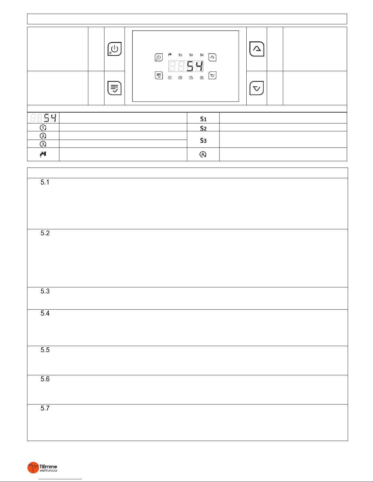
4. Control Panel: USE AND FUNCTIONS
ON/OFF
Exit the Menu
Grill Service
Shutter Manual Start
K1
K3
Scroll/Increase
Pump1 Test
Probes Menu
Enter User Menu
SET
Shower Key
K2
K4
Scroll/Decrease
Pump2 Test
Probes Menu
Fig. 3 Main Screen
S1 Probe Temperature
S1 Probe Displayed
P1 Output Activated
S2 Probe Displayed
P2 Output Activated
S3 Probe Displayed
Fashing: Ambient Thermostat open
P3 Output Activated
ON: Flow Switch Closed
Fashing: Shower Function Activated
P4 Output Activated
5. FUNCTIONALITIES
IGNITION/EXTINGUISHING
Controller Ignition/Extinguishing is perforemd by applying prolongued pressure to K1 key
OFF-mode is displayed by K1 key being turned-on
When the controller is turned on, the following messages will appear
o Product Code t002
o Product Revision r 0.1
o Configuration CF01
PROBE DISPLAY
The display shows the correct temperature sensor value S1 (S1 led is lit up).
To enter the probe menu press either K4 or K3, the temperature of Probe S2 is displayed (S2 Led flashes) or S3 (S3 Led
flashes)
By pressing K3 or K4 it is possible to scroll and check other connected probes
To exit the Menu press K1 or wait 10 seconds
If the probe reading is below the minimum range of the sensor the message Lo appears
If the probe reading is above the maximum range of the sensor the message Hi appears
SAFETY FEATURE
When this function is activated; P11=1, it starts a heat disposing process to remove excess heat buildup of the fireplace
The management of the safety feature is expalined in the plumbing/hydraulic schematic drawing parapraphs
ALARM FUNCTION
If the temperature measured by Sensor S1 exceeds the value of the thermostat alarm A08
An audible and visual signal is activated (the temperature flashes on the Display)
SILENCE Function: The audible signal can be turned off for 5 minutes by pressing any key. If the controller remains in
the alarm condition the audible signal will start again.
ANTIFREEZE FUNCTION
If the temperature measured by Probe S1 falls below the value of the Antifreeze Thermostat A06
The output for Pump P1 is turned on for t01 time at intervals of t02 time
The display will show the writing ICE
PUMP P1 ANTISEIZE FUNCTION
If Pump P1 remains inactive, also while OFF, for a time greater than Timer t05
The output for Pump P1 is turned-on for t04 seconds
The display will show the writing bLP
STANDBY FUNCTION
If the controller is OFF, and in ALARM, ANTIFREEZE or ANTISEIZE FUNCTION of Pump P1
The controller automatically turns itself ON
At the end of ANTIFREEZE or ANTISEIZE of Pump P1 functions, the controller will turn itself OFF.
Al the end of ALARM function the controller will remain ON

Pag. 3/15
0CAR6IN019124_Manual_GLH110_Rev_0.3
PUMP P1 FUNCTIONING TEST
When the controller is OFF, prolongued pressure of K3 key:
P1 output is activated for as long as the key is pressed and the display will show tSt1
PUMP P2 FUNCTIONING TEST
When the controller is OFF, prolongued pressure of K4 key:
P2/P4 output is activated for as long as the key is pressed and the display will show tSt2
SERVICE OUTPUT
P4 SERVICE output is programable from the Installer MENU by using parameter P06:
P06 = 0 DISABLED: the output does not work.
P06 = 1 THERMOSTAT: the output is activated if the temperature of S1 probe is above Thermostat A09.
P06 = 2 GRILL: press K1 key to turn on/off the output.
P06 = 3 AIR DAMPER: this output is used to manage an Air Damper to adjust for Combustion Air Flow.
AIR DAMPER
To make use of the Air Damper function set parameter P06 = 3
If the output is ON the Air Damper will be Open, if the output OFF the Air Damper will be closed.
The Air Damper will stay Open as long as the temperature of S1 probe is below A05 Thermostat. The Air Damper will close
when the temperature is above this Thermostat.
If P12 = 1 the Start Manual function is enabled:
If S1 Temperature is below A01, the Air Damper will Close. During the Ignition phase of the Fireplace, by pressing K1 key
the Air Damper will Open manually (the output corresponding Led will flash). When the Temperature falls below A01,
Thermostat after t06 time the Air Damper will close automatically.
PROBE TYPE
The controller can manage NTC10K, NTC100K and PT1000 type of probes, which can be configured by using parameters
P01, P02, P03 and P17 of the Installer MENU.
Fireplace Probe: P01 = 0 → NTC10K; P01 = 1 → NTC100K; P01 = 2 → PT1000
DHW Boiler Probe/ Tall Buffer : P02 = 0 → NTC10K; P02 = 1 → NTC100K; P02 = 2 → PT1000
Short Buffer Probe: P03 = 0 → NTC10K; P03 = 1 → NTC100K; P03 = 2 → PT1000
Ambient Probe: P04 = 0 → NTC10K; P04 = 1 → NTC100K; P04 = 2 → PT1000
Manifold Probe: P17 = 0 → NTC10K; P17 = 1 → NTC100K; P17 = 2 → PT1000
S3 INPUT CONFIGURATION
Parameter P05 can be enabled to mange the following:
P05 = 0, S3 input = DISABLED
P05 = 1, S3 input = PRESSURE SENSOR
P05 = 2, S3 input = AMBIENT SENSOR
P05 = 3, S3 input = AMBIENT SENSOR
PRESSURE SENSOR
If P05=1 pressure sensor management is enabled on probe S3.
If P07=1 pressure sensor errors are enabled:
If Water Pressure < Pr1 dispaly shows PrLo + audible signal.
If Water Pressure > Pr2 dispaly shows PrHi + audible signal.
PROBE SENSOR/AMBIENT THERMOSTAT
Parameter P05 can be setup to enable the management of the Probe Sensor/Ambient Thermostat
If the Ambient Temperature S3>b01 or the Ambient Thermostat is Open ( Led flashing) and there is NO DHW request
The Shutter is closed
The hydraulic/plumbing plants with a Buffer tank; if the Ambient Temperature is S3>b01 or the Ambient Thermostat is
Open the Heating Pump will be turned off (deactivated)
SHOWER
(P13=1) if used in specific hydraulic/plumbing plants where it is required, it can be enabled by pressing K2 key for 3 sec:
The display shows T03 time (minutes) giving (DHW) Domestic Hot Water priority;
K3 and K4 keys increase /decrease the duration
Wait 5 seconds to save and exit from this setup.
To exit without saving press K1 key.
T03 time is signaled by led flashing, giving priority to DHW production based on the type of hydraulic/plumbing plant
in use.
This function is over when
T03 time has expired.
By pressing again K2 key
If the temperature of S1 Probe is greater than A07 Safety Thermostat:
And T03=0, the shower function can be disabled by pressing K2 key.
Pag. 4/15
0CAR6IN019124_Manual_GLH110_Rev_0.3
SOLAR CIRCUIT
Buffer Tank Loading:
The Solar Manifold Pump is activated:
If the Temperature of (S3) >A33 and Δ (S3-S2) > d02
The Buffer Loading is disabled once the Buffer Comfort Thermostat has been reached on S2 (A20).
Manifold and Buffer Safety:
If the Temperature of the Manaifold (S3) > A35 (Manifold Safety Thermostat) the Manifold Pump is turned on again and
fills the Buffer Tank until A23 high temp. Thermostat has been reached.
Manifold Protection:
If the manifold Temperature (S3) > A36 (Manifold Safety Thermostat) the manifold pump is turned off
Antifreeze:
When this function is enabled (P09=1) if the temperature detected by S3 probe (even while the controller is OFF) falls
below the Antifreeze Thermostat A34 the manifold pump is turned on for t04 time at intervals of t05 time
WOOD INTEGRATION PRIORITY (Hydraulic/Plumbing plants including Buffer Tank)
This feature gives priority to the integration of the fireplace instead of the Gas boiler.
Se P10=1 priority is given to the wood fireplace in managing the integration of the Buffer Tank instead if the Gas Boiler.
PUMPS MANAGEMENT WITH PWM CONTROL
P18 and P19 parameters are used to enable and select the operating mode of the PWM1 and PWM2 signals, to manage the
pumps provided in the hydraulic/plumbing schemes:
PWM1: P18 = 0 → Disabled; P18 = 1 → Manual; P18 = 2 → Automatic
PWM2: P19 = 0 → Disabled; P19 = 1 → Manual; P19 = 2 → Automatic
PWM Disabled:
The pumps are controlled exclusively via 230V outputs
PWM Manual:
The PWM duty cycle which determines the speed of the pumps is set with the following parameters:
U06 if PWM1 with Heating profile (Fireplace Pump)
U16 if PWM2 with Heating profile (Heating Pump)
U26 if PWM2 with Solar profile (Solar manifold Pump)
Automatic PWM:
In relation to the type of pump, the PWM duty cycle is calculated on the basis of the temperature of the fireplace probe,
high Buffer Tank probe or solar manifold probe and can vary within the following ranges:
Between U01 and U02 if PWM1 with Heating profile (es. 85 ÷ 5 %)
Between U11 and U12 if PWM2 with Heating profile (es. 85÷ 5 %)
Between U21 and U22 if PWM2 with Solar profile (es. 15 ÷ 95 %)
Fireplace Pump speed change is enabled within the following temperature range:
Between A01 and A01+A80 in heating management (ex. if A01=35°C, A80=20°C then range: 35 ÷ 55 °C)
Between A01 and A01+A81 in DHW management (ex. if A01=35°C, A81=15°C then range: 35 ÷ 50 °C)
Heating Pump Speed change is enabled within the following temperature range:
Between A04 and A04+A82 (ex. if A04=45°C, A82=20°C then range: 45 ÷ 65 °C)
Or if the Buffer Tank is present
Between A17 and A17+A82 (ex. if A17=45°C, A82=20°C then range: 45 ÷ 65 °C)
Solar manifold Pump speed change is enabled within the following temperature range:
Between A33 and A33+A82 (ex. if A33=45°C, A82=20°C then range: 45 ÷ 65 °C)
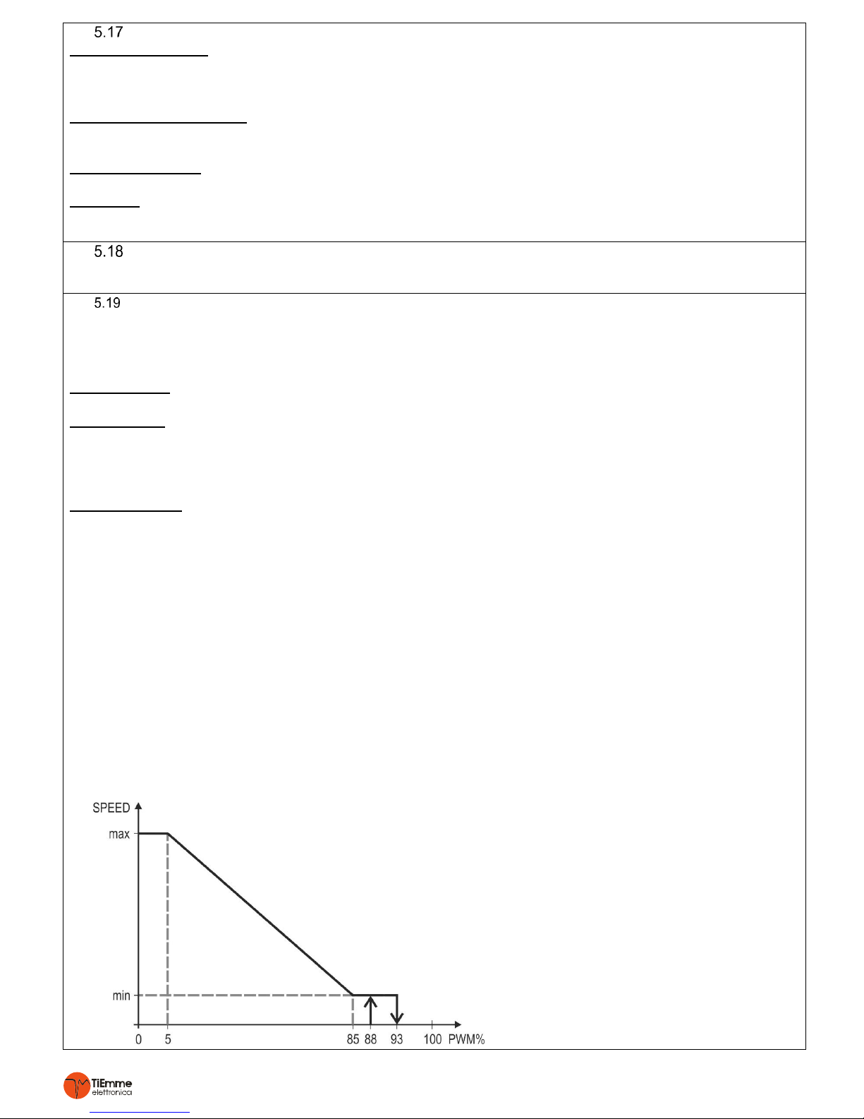
The profile of the PWM signal, Heating or Solar, is selected automatically on the basis of the pump that needs to be
managed and the following are the profiles of the pumps that can be found on the market:
HEATING Profile
On the basis of this profile it is advisable to set
the PWM duty cycle parameters as shown
below:
PWM1
Vmin: U01 <= 85%
Vmax: U02 >= 5%
PWM2
Vmin: U11 <= 85%
Vmax: U12 >= 5%
Pag. 5/15
0CAR6IN019124_Manual_GLH110_Rev_0.3
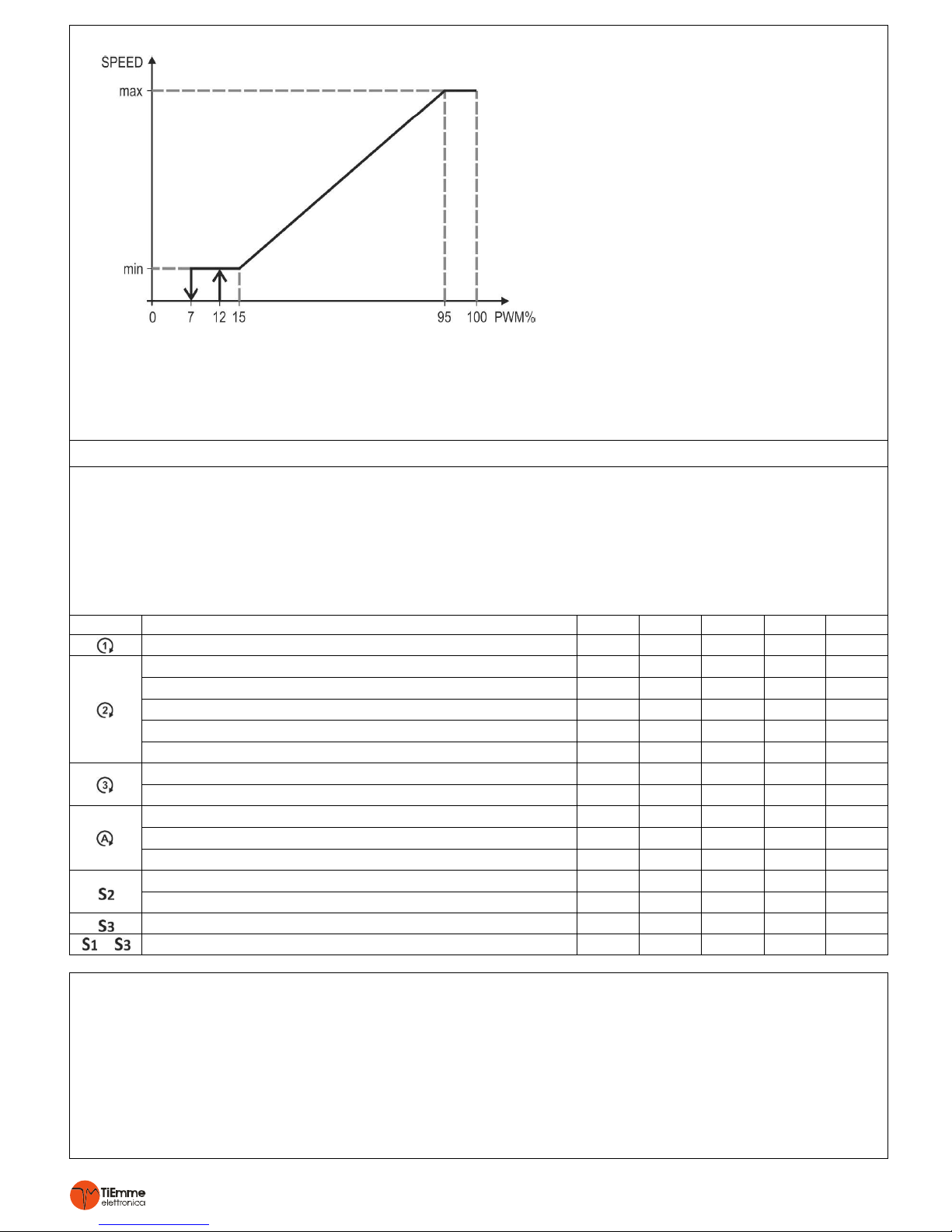
SOLAR Profile
On the basis of this profile it is advisable to set
the PWM duty cycle parameters as shown
below:
PWM2
Vmin: U01 >= 15%
Vmax: U02 <= 95%
In the following conditions the PWM can be setup with the following parameters:
ANTIFREEZE: U03, U13 e U23
SAFETY: U04, U14 e U24
ANTISEIZE: U05, U15 e U25
6. MENU’
6.1 MAIN MENU
To enter into the main menu simply click on K2 key:
Keys K3 and K4 are used to scroll through various parameters signaled by the corresponding flashing led.
Press K2 key to modify (the led remains solid while value flashes).
Keys K3 and K4 are used to change the parameter value.
Press K2 to save the new value.
Press K1 to exit without saving.
Press K1 again to exit the Menu or wait 30 seconds.
Led
Description
Code
Min
Set
Max
U.M.
Low Temp. Thermostat for Fireplace Pump
A01
20
35
90
[°C]
Diverting Valve Thermostat on Fireplace probe
A02
20
45
90
[°C]
Heating Pump Thermostat on Fireplace probe
A04
20
45
90
[°C]
Heating Pump Thermostat on high Buffer Tank probe
A17
20
45
90
[°C]
Service Thermostat on Fireplace probe
A09
20
50
90
[°C]
Valve Thermostat for DHW priority
A24
20
70
90
[°C]
Thermostat to activate Integration on Fireplace probe
A03
20
45
90
[°C]
Thermostat Integration Buffer Tank on High Buffer Tank Probe
A19
20
45
90
[°C]
Heating Pump Thermostat on Fireplace probe
A04
20
45
90
[°C]
Service Thermostat on Fireplace probe
A09
20
50
90
[°C]
Heating Pump Thermostat on High Buffer Tank probe
A17
20
45
90
[°C]
DHW Boiler Thermostat on S2
A18
20
50
90
[°C]
Buffer Comfort Thermostat on High Buffer Tank probe
A20
20
60
90
[°C]
Ambient Probe Thermostat on S3
b01 5 20
50
[°C]
+
Differential Thermostat Fireplace-Boiler DHW/Buffer
d01 5 20
2
[°C]
6.2 INSTALLER MENU
Only QUALIFIED PERSONEL must access this MENU , because if the set parameters are changed this could make the
product completely unsuitable for the application.
To enter into the INSTALLER MENU press at the same time K2 and K4 keys for 3 seconds.
To scroll through the parameter codes use K3 and K4 keys.
To view the value of a parameter and to enter modification mode press K2 key.
To modify the value press K3 and K4 keys.
To save the new value press K2 key.
To exit without saving press K1 key.
Press K1 again to exit the Menu or wait 60 seconds.
 Loading...