

Tieline VIA User Manual
Codec User Manual
Software Version: 2.16.xx
Manual Version: 1.2
December, 2016

2
ViA User Manual v1.2
Table of Contents
Part 1 W arnings & Safety Information
Part 2 How to U se the Documentation
Part 3 Glossary of Terms
Part 4 Items Shipped with ViA
Part 5 Introduction
Part 6 Battery Use and Power
Management
Part 7 Inserting and Removing Modules
Part 8 External Connections
Part 9 Codec Controls
Part 10 Wireless IP Connection Options
6
10
11
13
14
15
21
22
26
28
Part 11 Menu Navigation
Part 12 Codec Menus
Part 13 Connection Guide
... ....... ....... .... ....... .... ....... ....... .... ....... ....... .... ....... .... ....... ....... .... ....... ....... .... ....... .... ..... 371 Connecting over IP
... ....... ....... .... ....... .... ....... ....... .... ....... ....... .... ....... .... ....... ....... .... ....... ....... .... ....... .... ..... 422 Monitoring IP Connections
... ....... ....... .... ....... .... ....... ....... .... ....... ....... .... ....... .... ....... ....... .... ....... ....... .... ....... .... ..... 443 Connecting over SIP
... ....... ....... .... ....... .... ....... ....... .... ....... ....... .... ....... .... ....... ....... .... ....... ....... .... ....... .... ..... 504 Connecting with Fuse-IP
... ....... ....... .... ....... .... ....... ....... .... ....... ....... .... ....... .... ....... ....... .... ....... ....... .... ....... .... ..... 545 Connecting with ISDN
... ....... ....... .... ....... .... ....... ....... .... ....... ....... .... ....... .... ....... ....... .... ....... ....... .... ....... .... ..... 596 Connecting POTS
Part 14 Redialing a Connection
Part 15 Load, Connect and Manage
Programs
Part 16 ViA H eadphone Controls
Part 17 Input Levels and Input Settings
33
35
36
63
64
70
73
Part 18 PPM Meters and Analog Audio
Outputs
81
© Tieline Pty. Lt d. 2016

3ViA User Manual v1.2
Part 19 Cue and Talkback Operati on
Part 20 General Audio Settings
Part 21 Configuring AES3 and AES42
Input Audio
Part 22 Backup and Redundancy
Options
... ....... ....... .... ....... .... ....... ....... .... ....... ....... .... ....... .... ....... ....... .... ....... ....... .... ....... .... ..... 1031 Monitoring SmartStream PLUS
... ....... ....... .... ....... .... ....... ....... .... ....... ....... .... ....... .... ....... ....... .... ....... ....... .... ....... .... ..... 1042 Managing Failover
Part 23 Administrator and Basic
Operation Modes
Part 24 About I SDN Modules
... ....... ....... .... ....... .... ....... ....... .... ....... ....... .... ....... .... ....... ....... .... ....... ....... .... ....... .... ..... 1141 ISDN Module Settings
... ....... ....... .... ....... .... ....... ....... .... ....... ....... .... ....... .... ....... ....... .... ....... ....... .... ....... .... ..... 1192 ISDN Answering Configuration
Part 25 About POTS Modules
86
89
96
100
106
112
122
... ....... ....... .... ....... .... ....... ....... .... ....... ....... .... ....... .... ....... ....... .... ....... ....... .... ....... .... ..... 1241 POTS Module Settings
... ....... ....... .... ....... .... ....... ....... .... ....... ....... .... ....... .... ....... ....... .... ....... ....... .... ....... .... ..... 1282 POTS Answering Configuration
Part 26 About SIP
... ....... ....... .... ....... .... ....... ....... .... ....... ....... .... ....... .... ....... ....... .... ....... ....... .... ....... .... ..... 1331 Configuring SIP Accounts
... ....... ....... .... ....... .... ....... ....... .... ....... ....... .... ....... .... ....... ....... .... ....... ....... .... ....... .... ..... 1362 Configuring SIP Interfaces
Part 27 Other Touch Screen
Configuration Tasks
... ....... ....... .... ....... .... ....... ....... .... ....... ....... .... ....... .... ....... ....... .... ....... ....... .... ....... .... ..... 1391 Configuring LAN/VLAN Settings
... ....... ....... .... ....... .... ....... ....... .... ....... ....... .... ....... .... ....... ....... .... ....... ....... .... ....... .... ..... 1452 Adding Cellular Access Points
... ....... ....... .... ....... .... ....... ....... .... ....... ....... .... ....... .... ....... ....... .... ....... ....... .... ....... .... ..... 1473 Selecting an Algorithm
... ....... ....... .... ....... .... ....... ....... .... ....... ....... .... ....... .... ....... ....... .... ....... ....... .... ....... .... ..... 1554 Configuring the Jitter Buffer
... ....... ....... .... ....... .... ....... ....... .... ....... ....... .... ....... .... ....... ....... .... ....... ....... .... ....... .... ..... 1615 Configuring Forward Error Correction
... ....... ....... .... ....... .... ....... ....... .... ....... ....... .... ....... .... ....... ....... .... ....... ....... .... ....... .... ..... 1646 Configuring Auto Reconnect
... ....... ....... .... ....... .... ....... ....... .... ....... ....... .... ....... .... ....... ....... .... ....... ....... .... ....... .... ..... 1657 Configuring Encode/Decode Direction
... ....... ....... .... ....... .... ....... ....... .... ....... ....... .... ....... .... ....... ....... .... ....... ....... .... ....... .... ..... 1668 Headphone Settings
... ....... ....... .... ....... .... ....... ....... .... ....... ....... .... ....... .... ....... ....... .... ....... ....... .... ....... .... ..... 1679 Enabling Relays & RS232 Data
... ....... ....... .... ....... .... ....... ....... .... ....... ....... .... ....... .... ....... ....... .... ....... ....... .... ....... .... ..... 16910 Configuring TCP/UD P Ports
... ....... ....... .... ....... .... ....... ....... .... ....... ....... .... ....... .... ....... ....... .... ....... ....... .... ....... .... ..... 17311 Configuring QoS for IP Packets
... ....... ....... .... ....... .... ....... ....... .... ....... ....... .... ....... .... ....... ....... .... ....... ....... .... ....... .... ..... 17512 Reset and Restore Factory Default Settings
... ....... ....... .... ....... .... ....... ....... .... ....... ....... .... ....... .... ....... ....... .... ....... ....... .... ....... .... ..... 17713 Configuring Via Interfaces
... ....... ....... .... ....... .... ....... ....... .... ....... ....... .... ....... .... ....... ....... .... ....... ....... .... ....... .... ..... 17914 Configuring SNMP Settings
... ....... ....... .... ....... .... ....... ....... .... ....... ....... .... ....... .... ....... ....... .... ....... ....... .... ....... .... ..... 18115 Configuring Country of Use
130
139
© Tieline Pty. Lt d. 2016

4
ViA User Manua l v1.2
... ....... ....... .... ....... .... ....... ....... .... ....... ....... .... ....... .... ....... ....... .... ....... ....... .... ....... .... ..... 18216 Typing and Language Options
... ....... ....... .... ....... .... ....... ....... .... ....... ....... .... ....... .... ....... ....... .... ....... ....... .... ....... .... ..... 18417 Configuring Web-GUI Settings
... ....... ....... .... ....... .... ....... ....... .... ....... ....... .... ....... .... ....... ....... .... ....... ....... .... ....... .... ..... 18518 Lock or Unlock a Program in the Codec
... ....... ....... .... ....... .... ....... ....... .... ....... ....... .... ....... .... ....... ....... .... ....... ....... .... ....... .... ..... 18719 Power Shut Down Options
... ....... ....... .... ....... .... ....... ....... .... ....... ....... .... ....... .... ....... ....... .... ....... ....... .... ....... .... ..... 18820 Adjust ing Time Settings
... ....... ....... .... ....... .... ....... ....... .... ....... ....... .... ....... .... ....... ....... .... ....... ....... .... ....... .... ..... 18921 About Unit Details
Part 28 Connecting to the ToolBox
Web-GUI
... ....... ....... .... ....... .... ....... ....... .... ....... ....... .... ....... .... ....... ....... .... ....... ....... .... ....... .... ..... 1911 Opening the Java or HTML5 Web-GUI & Login
... ....... ....... .... ....... .... ....... ....... .... ....... ....... .... ....... .... ....... ....... .... ....... ....... .... ....... .... ..... 1942 Changing the Default Pas sword
190
Part 29 Using the Java Toolbox Web-GUI
... ....... ....... .... ....... .... ....... ....... .... ....... ....... .... ....... .... ....... ....... .... ....... ....... .... ....... .... ..... 2031 Configuring IP Sett ings
... ....... ....... .... ....... .... ....... ....... .... ....... ....... .... ....... .... ....... ....... .... ....... ....... .... ....... .... ..... 2072 Configure Cellular Modems
... ....... ....... .... ....... .... ....... ....... .... ....... ....... .... ....... .... ....... ....... .... ....... ....... .... ....... .... ..... 2093 Configure Fus e-IP Bonding
... ....... ....... .... ....... .... ....... ....... .... ....... ....... .... ....... .... ....... ....... .... ....... ....... .... ....... .... ..... 2104 Configuring ISDN
... ....... ....... .... ....... .... ....... ....... .... ....... ....... .... ....... .... ....... ....... .... ....... ....... .... ....... .... ..... 2185 Configuring POTS
... ....... ....... .... ....... .... ....... ....... .... ....... ....... .... ....... .... ....... ....... .... ....... ....... .... ....... .... ..... 2246 Configuring Input/Output Settings
... ....... ....... .... ....... .... ....... ....... .... ....... ....... .... ....... .... ....... ....... .... ....... ....... .... ....... .... ..... 2297 Configure Mono or Stereo Peer-to-Peer Programs in ViA
... ....... ....... .... ....... .... ....... ....... .... ....... ....... .... ....... .... ....... ....... .... ....... ....... .... ....... .... ..... 2378 Configure Mono or Stereo + IFB Dialing Programs
... ....... ....... .... ....... .... ....... ....... .... ....... ....... .... ....... .... ....... ....... .... ....... ....... .... ....... .... ..... 2499 Configure 2 Mono Peer-t o- Peer Dialing Connections
... ....... ....... .... ....... .... ....... ....... .... ....... ....... .... ....... .... ....... ....... .... ....... ....... .... ....... .... ..... 25610 Configure and Regist er SIP Acc ount s
... ....... ....... .... ....... .... ....... ....... .... ....... ....... .... ....... .... ....... ....... .... ....... ....... .... ....... .... ..... 25811 Configure SIP Interfaces
... ....... ....... .... ....... .... ....... ....... .... ....... ....... .... ....... .... ....... ....... .... ....... ....... .... ....... .... ..... 26012 SIP Peer-to-Peer Programs
... ....... ....... .... ....... .... ....... ....... .... ....... ....... .... ....... .... ....... ....... .... ....... ....... .... ....... .... ..... 26413 2 x Mono Peer-to- Peer SIP Programs
... ....... ....... .... ....... .... ....... ....... .... ....... ....... .... ....... .... ....... ....... .... ....... ....... .... ....... .... ..... 26814 Dial and Dis c onnect a Program
... ....... ....... .... ....... .... ....... ....... .... ....... ....... .... ....... .... ....... ....... .... ....... ....... .... ....... .... ..... 26915 Dial/Disconnect Multiple Audio Streams
... ....... ....... .... ....... .... ....... ....... .... ....... ....... .... ....... .... ....... ....... .... ....... ....... .... ....... .... ..... 27116 Adjust ing the Connection Bit Rate
... ....... ....... .... ....... .... ....... ....... .... ....... ....... .... ....... .... ....... ....... .... ....... ....... .... ....... .... ..... 27117 View/Edit/Delete Programs
... ....... ....... .... ....... .... ....... ....... .... ....... ....... .... ....... .... ....... ....... .... ....... ....... .... ....... .... ..... 27318 Reset Factory Default Settings
... ....... ....... .... ....... .... ....... ....... .... ....... ....... .... ....... .... ....... ....... .... ....... ....... .... ....... .... ..... 27319 Backup and Restore Functions
... ....... ....... .... ....... .... ....... ....... .... ....... ....... .... ....... .... ....... ....... .... ....... ....... .... ....... .... ..... 27520 Lock or Unlock Programs
... ....... ....... .... ....... .... ....... ....... .... ....... ....... .... ....... .... ....... ....... .... ....... ....... .... ....... .... ..... 27621 Configure Country Sett ing
... ....... ....... .... ....... .... ....... ....... .... ....... ....... .... ....... .... ....... ....... .... ....... ....... .... ....... .... ..... 27722 Configuring SNMP in the Codec
... ....... ....... .... ....... .... ....... ....... .... ....... ....... .... ....... .... ....... ....... .... ....... ....... .... ....... .... ..... 27823 Download Logs
... ....... ....... .... ....... .... ....... ....... .... ....... ....... .... ....... .... ....... ....... .... ....... ....... .... ....... .... ..... 27924 RS232 Data Configuration
... ....... ....... .... ....... .... ....... ....... .... ....... ....... .... ....... .... ....... ....... .... ....... ....... .... ....... .... ..... 28125 Creating Rules
... ....... ....... .... ....... .... ....... ....... .... ....... ....... .... ....... .... ....... ....... .... ....... ....... .... ....... .... ..... 28426 Upgrading Codec Firmware
195
Part 30 Using the H TML5 Toolbox
Web-GUI
... ....... ....... .... ....... .... ....... ....... .... ....... ....... .... ....... .... ....... ....... .... ....... ....... .... ....... .... ..... 2961 Using the HTML5 Toolbox Quick Connect Web-GUI
285
© Tieline Pty. Lt d. 2016

... ....... ....... .... ....... .... ....... ....... .... ....... ....... .... ....... .... ....... ....... .... ....... ....... .... ....... .... ..... 3042 Configuring IP Sett ings
... ....... ....... .... ....... .... ....... ....... .... ....... ....... .... ....... .... ....... ....... .... ....... ....... .... ....... .... ..... 3093 Configure Cellular Modems
... ....... ....... .... ....... .... ....... ....... .... ....... ....... .... ....... .... ....... ....... .... ....... ....... .... ....... .... ..... 3104 Configure Fus e-IP Bonding
... ....... ....... .... ....... .... ....... ....... .... ....... ....... .... ....... .... ....... ....... .... ....... ....... .... ....... .... ..... 3135 Configuring ISDN
... ....... ....... .... ....... .... ....... ....... .... ....... ....... .... ....... .... ....... ....... .... ....... ....... .... ....... .... ..... 3206 Configuring POTS
... ....... ....... .... ....... .... ....... ....... .... ....... ....... .... ....... .... ....... ....... .... ....... ....... .... ....... .... ..... 3267 Configuring Input/Output Settings
... ....... ....... .... ....... .... ....... ....... .... ....... ....... .... ....... .... ....... ....... .... ....... ....... .... ....... .... ..... 3338 Configuring SIP
... ....... ....... .... ....... .... ....... ....... .... ....... ....... .... ....... .... ....... ....... .... ....... ....... .... ....... .... ..... 3399 Load, Unload and Dial a Program
... ....... ....... .... ....... .... ....... ....... .... ....... ....... .... ....... .... ....... ....... .... ....... ....... .... ....... .... ..... 34210 Adjust ing the Connection Bit Rate
... ....... ....... .... ....... .... ....... ....... .... ....... ....... .... ....... .... ....... ....... .... ....... ....... .... ....... .... ..... 34311 Reset Factory Default Settings
... ....... ....... .... ....... .... ....... ....... .... ....... ....... .... ....... .... ....... ....... .... ....... ....... .... ....... .... ..... 34412 Backup and Restore Functions
... ....... ....... .... ....... .... ....... ....... .... ....... ....... .... ....... .... ....... ....... .... ....... ....... .... ....... .... ..... 34513 Lock or Unlock Programs
... ....... ....... .... ....... .... ....... ....... .... ....... ....... .... ....... .... ....... ....... .... ....... ....... .... ....... .... ..... 34714 Configure Country Sett ing
... ....... ....... .... ....... .... ....... ....... .... ....... ....... .... ....... .... ....... ....... .... ....... ....... .... ....... .... ..... 34815 Configuring SNMP in the Codec
... ....... ....... .... ....... .... ....... ....... .... ....... ....... .... ....... .... ....... ....... .... ....... ....... .... ....... .... ..... 34916 Download Logs
... ....... ....... .... ....... .... ....... ....... .... ....... ....... .... ....... .... ....... ....... .... ....... ....... .... ....... .... ..... 35017 RS232 Data Configuration
... ....... ....... .... ....... .... ....... ....... .... ....... ....... .... ....... .... ....... ....... .... ....... ....... .... ....... .... ..... 35118 Creating Rules
... ....... ....... .... ....... .... ....... ....... .... ....... ....... .... ....... .... ....... ....... .... ....... ....... .... ....... .... ..... 35519 Upgrading Codec Firmware
5ViA User Manua l v1.2
Part 31 Reference
... ....... ....... .... ....... .... ....... ....... .... ....... ....... .... ....... .... ....... ....... .... ....... ....... .... ....... .... ..... 3561 Installing the Codec at the Studio
... ....... ....... .... ....... .... ....... ....... .... ....... ....... .... ....... .... ....... ....... .... ....... ....... .... ....... .... ..... 3622 Understanding IP Networks
... ....... ....... .... ....... .... ....... ....... .... ....... ....... .... ....... .... ....... ....... .... ....... ....... .... ....... .... ..... 3643 Tips for Creating Reliable IP Connections
... ....... ....... .... ....... .... ....... ....... .... ....... ....... .... ....... .... ....... ....... .... ....... ....... .... ....... .... ..... 3664 Tes t ing IP Network Connections
... ....... ....... .... ....... .... ....... ....... .... ....... ....... .... ....... .... ....... ....... .... ....... ....... .... ....... .... ..... 3685 Tes ting ISDN Connections
... ....... ....... .... ....... .... ....... ....... .... ....... ....... .... ....... .... ....... ....... .... ....... ....... .... ....... .... ..... 3686 Using Ans wer Routes for Sessionless ISDN Calls
... ....... ....... .... ....... .... ....... ....... .... ....... ....... .... ....... .... ....... ....... .... ....... ....... .... ....... .... ..... 3727 POTS Connection Tips & Precautions
... ....... ....... .... ....... .... ....... ....... .... ....... ....... .... ....... .... ....... ....... .... ....... ....... .... ....... .... ..... 3748 ViA Compliances and Certifications
... ....... ....... .... ....... .... ....... ....... .... ....... ....... .... ....... .... ....... ....... .... ....... ....... .... ....... .... ..... 3759 ViA Declaration of Conformity
... ....... ....... .... ....... .... ....... ....... .... ....... ....... .... ....... .... ....... ....... .... ....... ....... .... ....... .... ..... 37610 Software Licences
... ....... ....... .... ....... .... ....... ....... .... ....... ....... .... ....... .... ....... ....... .... ....... ....... .... ....... .... ..... 37711 Trademarks and Credit Notices
Part 32 ViA Specifications
Part 33 Appendix A: RS232 and Control
Port Wiring
Part 34 Appendix B: Default Matrix
Routing
356
378
380
382
© Tieline Pty. Lt d. 2016
Index 385

6 ViA User Manua l v1.2
1. The power cable and battery must be removed from the device for Power Disconnection.
2. Remove phone or IS DN cables from the codec before removing a module or servici ng.
THUNDERSTORM AND LIGHTNING W ARNING:
DO NOT USE Tieline codecs during thunderstorms and lightning. You may s uffer an injury
using a phone, Ti eline codec, or any device connected t o a phone during a t hunderstorm.
This can lead to personal injury and in extreme c ases may be fatal. Protect ive devices c an
be fitt ed to the line, however, due to the extremely high voltages and energy levels involved i n
lightning strikes , these devices m ay not offer protection to t he users, or t he Tieline codec
and equipment connected to the codec.
Secondary strikes can occur. These s econdary st rikes are induced by lightning st rikes and
also produce dangerously high currents and energy levels. You only need t o be near an
object struck by lightning t o lead t o personal injury or damage to equipment. e. g. i f you are
located near a lighting tower at a s ports facilit y, water features and drains on golf c ourses,
you may be affected by these secondary strikes.
Damage to personnel and Tieline codecs may occ ur during thunderstorm, even if the c odec
is turned off but remains connected to the phone or ISDN system, LAN o r t he power.
ANY DAMAGE TO A TIELINE PRODUCT CAUSED BY LIGHTNING or an ELECTRICAL
STORM W ILL VOID THE WARRANTY.
DIGITAL PHONE S YSTEM WARNING:
DO NOT CONNECT THE ANALOG POTS MODULE TO A DIGITAL PHONE SYSTEM.
PERMANENT DAMAGE MA Y OCCUR! If y ou are unfamili ar with any facilit y, c heck t hat the
line you are using is NOT a digital line. If the Tieline codec becomes faulty due to the use of
a digital phone sy s tem, the W ARRANTY WILL BE V OID.
SAFETY P RECAUTION:
· Any procedures that involve opening panels or changing components mus t be performed
by qualified servic e personnel only.
SERVICING WARNINGS:
· Do not perform any servicing other than that contained in the operating instructions
unless you are qualified to do so.
· All work should be carried out by s uit ably qualified personnel.
LINE VOLTAGE:
· Before connecting the AC adapter to the power line, make s ure the voltage of the power
source matc hes the requirements of the device. Refer to the device Specifications for
information about the c orrect power rating for the unit.
WARNING: To Redu ce the Risk of Ele ctrica l S hock a n d Fire
1. All servic ing must be undertaken only by qualified s ervice personnel. There are not user
servic eable parts inside the unit.
2. DO NOT plug in, turn on or attempt to operat e an obviously damaged unit.
3. Ensure that the chassis ventilation slots/holes in the unit are NOT COVERED OR
BLOCKED.
4. Do not operate the device in a location where the maximum ambient temperature
exceeds 40°C (104°F), or is below 0°C (32°F).
1 Warnings & Safety Information
© Tieline Pty. Lt d. 2016
ViA User Manua l v1.2
LITHIUM-ION BATTERY WARNINGS:
1. Please read the RRC2057 battery user manual shipped with this product before use. It
includes very important safety, c harging, operational and disposal information. This us er
manual can also be downlo a d e d at http://www.rrc-ps.com/.
2. For safety reasons, the battery is prevented from discharging (i.e. from powering t he
codec) if the internal temperature reaches a pre-set t hreshold. If a battery t emperature
warning is displayed, the battery should be removed from the codec and allowed to cool.
3. For safety reasons, the batt ery i s prevented from c harging if t he internal temperature
reaches a pre-s et t hreshold. Move the codec to a c ooler locati on to allow t he batt ery to
continue charging.
4. If a battery is ins talled and the “battery unavailable” ic on appears (or t he batt ery icon
doesn’t appear at all). The battery should immediately be removed from the codec.
Please contac t Tieline if this s i t uation persist s.
5. The battery may continue to charge when external power is applied to the codec even
when the codec is off.
6. When external power is not being applied to the codec, t he battery will dis c harge s lowly
even if the codec is off. To avoid depleting t he batt ery it s hould be removed from t he
codec when not in use.
BATTERY TRANSPORTATION
1. This device includes a Lithium-ion battery and it is t he owner’s responsibilit y to ship t his
device in full compliance with all of the latest applicable transportation regulations. For
air transport, refer to current IATA and FAA regulations, as appropriate, and to your
carrier for air transport compliance information. For worl dwide sea transportation
compliance information refer to the IMO-IMDG code (special provision 188). For
European road transportation compliance information see ADR (special provis ion 188).
2. When the codec is first shipped from Tieline to t he customer the batt ery pack is
delivered in shipping-mode (stat us dis play off, no measurable voltage at the connector).
3. Please request the RRC2057 Material Safety Data Sheet from RRC at http://www.rrc-
ps.com/ for additional transportation and regulatory inform ati on.
GENERAL WARNINGS:
1. Do not operate the codec on a hot s urface.
2. Only operate the codec within the specified environmental conditions. The codec is
considered to be in an operational state when external power is being s upplied or the
battery is ins talled, even if the codec is off.
3. If the environmental conditions exceed the specified values, the codec should be
switc hed off, external power should be removed and the battery s hould be removed from
the codec.
RADIO FREQUENCY SAFET Y INFORMATION:
IMPORTANT: To sati sfy radio frequency exposure c ompliance requirements, the antenna
and transmitt er in the ViA c odec must be at least 20 c m from all persons and m ust not be
used in conjunction with any other antenna or transmit ter.
The device has an internal Wi-Fi antenna which is located at the rear of the unit. For
optimum performance with minimum power consumption do not shield t he devic e or c over
with any object. Covering the antenna affects signal quality, may cause the product to
operate at a higher power level than needed, and may shorten battery life.
SAFE LISTENING GUIDANCE
WARNING: LISTENING TO AUDIO AT EXCESSIVE VOLUMES CAN CAUSE
PERMANENT HEARING DAMAGE. USE AS LOW A VOLUME AS POSSI BLE.
Over exposure to excessive sound levels can damage your ears resulting in permanent
noise-induced hearing loss (NIHL). Please use applicable health and safety authority
7
© Tieline Pty. Lt d. 2016
8 ViA User Manua l v1.2
guidelines on maximum exposure limits. As a rule of thumb, avoid extended periods
list ening to sound pressure levels (SPLs ) of 85dBA or higher.
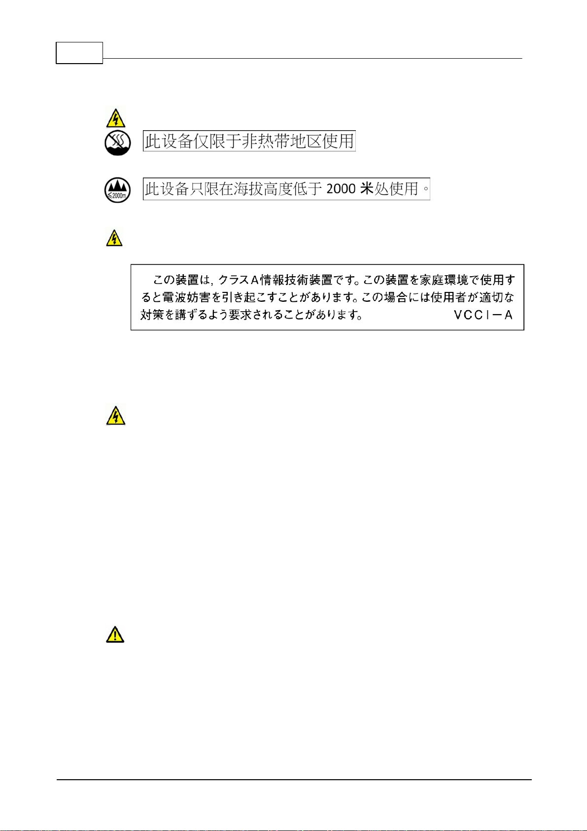
CHINES E SAFETY WARNINGS:
This device must only be used in not-tropical climat e regions.
This device must on ly be used at al t itude not exceedi ng 2000 meters.
JAPANESE SAFETY WARNINGS:
Statement for Class A VCCI-certified Equipment:
Translation of previous Cl ass A VCCI Stat ement: This is a Class A product based on t he
standard of the Voluntary Control Council for Interference by Information Technology
Equipment (VCCI). If this equipment is used in a domestic environment, radio dist urbance
may occur, in which case, t he user may be required to take c orrective acti on.
Spe ci al Notice s for North Ameri can Users:
For North American power connection, s elect a power s upply c ord that is UL Lis ted and
CSA Certified 3 - conductor, [18 AW G], terminated in a m olded on plug c ap rated 125 V, [5
A], with a minimum l ength of 1.5m [six feet] but no longer than 4.5m.
Spe ci al Notice s for Europea n Users:
For European connection, select a power supply c ord that is internationally harmonized and
marked “<HAR>”, 3 - conduct or, 0,75 mm2 minimum mm2 wire, rated 300 V , with a PV C
insulated jack et. The cord must have a molded on plug cap rated 250 V, 3 A .
Interconnection Cabl ing:
Cables for c onnecting to the unit's RS232 and Et hernet Interfac es mus t be UL c ertified ty pe
DP-1 or DP-2. (Note: when residing in non-LPS circuit)
Overcurren t Prote ction:
A readily acc ess ible list ed branch-circuit over current protect ive devi ce rated 15 A mus t be
incorporated in the building wiring for the power input.
Replaceable Batte ri es:
The equipment is provided with replaceable batteries, and if replaced by an incorrect battery
type, then an explosion may occur.
CAUTION: RISK OF EXPLOSION IF BATTERY IS REPLACED BY AN INCORRECT
BATTERY TYPE. DISP OSE OF USED BATTERIES ACCORDING TO THE I NSTRUCTIONS.
This equipment is provided with a long life replaceable Panasonic CR2032 model 3V
manganese dioxide lithium c oin battery. Servi ce personnel should only replace t his battery
with the same brand and type of battery. If this is replaced by an incorrect battery ty pe, then
© Tieline Pty. Lt d. 2016

ViA User Manua l v1.2
an explosion may occ ur. Contact t he manufact urer to view the Material Safety Data Sheet for
this batt ery.
This equipment is provided with a replaceable RRC2057 Lithium-ion battery. Service
personnel should only replace this batt ery with the same brand and t ype of battery. If this is
replaced by an incorrect battery type, then an explosion may occur. Contact the
manufac turer to vi ew the Material Safety Data Sheet for this batt ery.
9
End of Life Statement
Tieline hereby declares that all materials, c omponents and products s upplied are in full compliance
with RoHS & WEE directives. This product must be disposed of according to local laws and
regulations. Because the product contains a battery it must be disposed of separately from
household waste. Do not incinerate, but take it to a recyc l ing facility.
Warranty and Disclai mer
This equipment manufactured by Tieline is warranted by Tieline against defects in material and
workmanship for two years from the date of original purchase. During the warranty period, we will
repair or, at our option, replace at no charge a product that proves to be defective, provided y ou
obtain return authorization from Tieline and return the product, s hipping prepaid, to Tieline. For return
authorization, contact Tieline's US or Australian off ice (see http://www.tieline.com/Contact-Us).
This W arranty does not apply if the product has been damaged by accident or mis use or as the
result of service or modification performed by anyone other than Tieline. W ith the exception of the
warranties s et forth above, Tieline mak es no other warranties, expressed or implied or statutory,
including but not l imited t o warranties of merchantability and fitness for a particular purpose, which
are hereby expressly disclaimed. In no event shall Tieline have any liability for indirect,
consequential or punitive damages resulting from t he use of t his product. Use of this product is
subject t o Tieline's SOFTWARE LICENSE and WARRANTY conditions, which s hould be viewed at
http://www.tieline.com/Support/Product-Warranty before using this product .
Whils t every effort has been made to ensure the accuracy of t his m anual we are not responsible for
any errors or omiss ions within it. The product spec ifications and descripti ons within this m anual will
be subject to improvements and modificati ons over time without notic e, as changes t o s oftware and
hard war e are im plemented. This codec c an provide high volt ages on inputs and s uitable broadcast
equipment mus t be used at all tim es. Tieline takes no responsibilit y for any damage to equipment
attached to the c odec.
Battery Warranty
Tieline expressly dis claims any and all implied warranties on the RRC Li-ion S mart Bat tery P ack
RRC2057. The manufacturer's warranty applies. Contact t he battery manufacturer for any warranty
claims. To contact the battery manufacturer visit their website at http://www.rrc-ps.com/.
© Tieline Pty. Lt d. 2016
10 ViA User Manua l v1.2
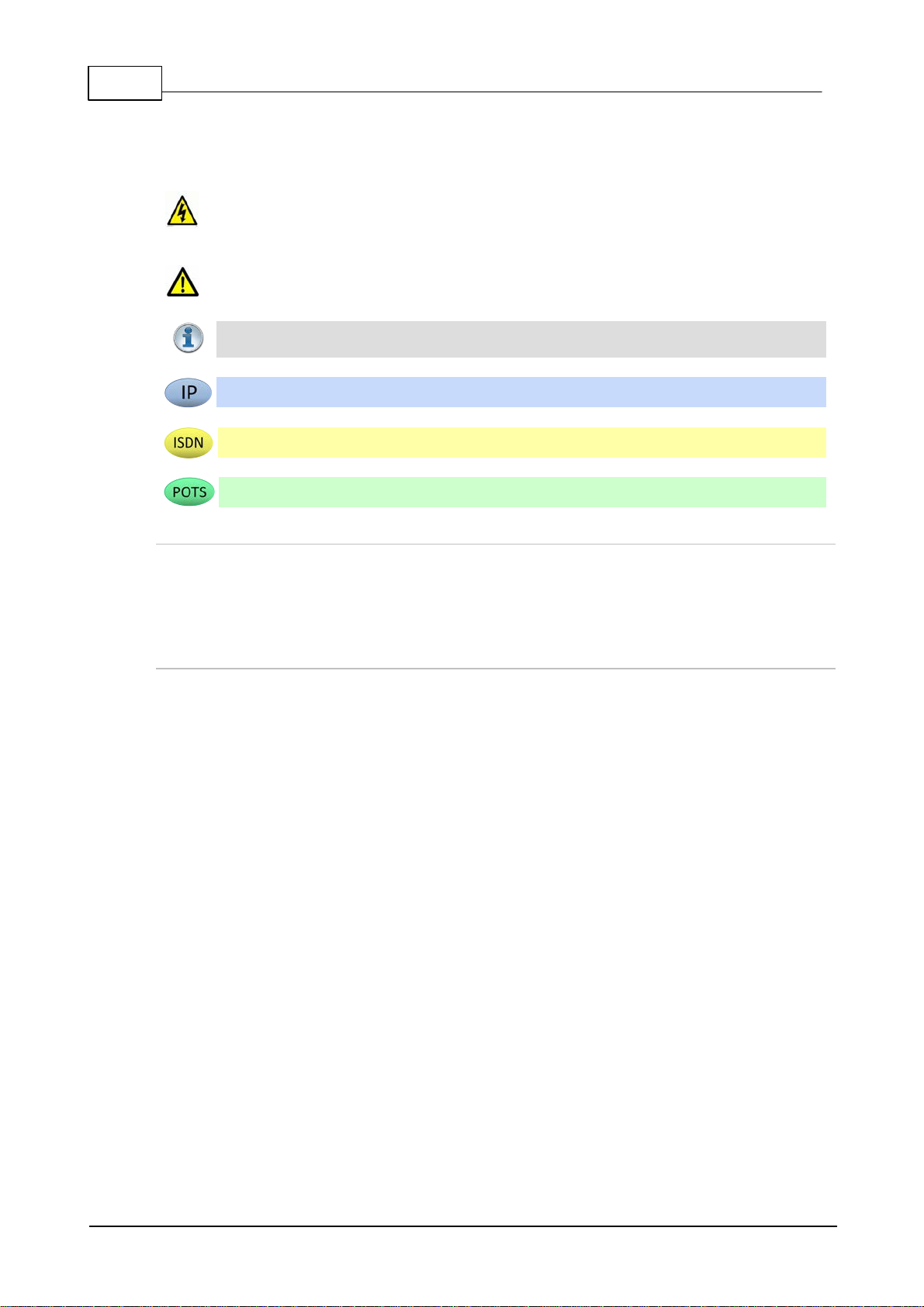
Warnings: Instruct ions t hat, i f ignored, could result in death or serious personal injury
caused by dangerous volt ages or incorrect operation of the equipment. These must be
observed for safe operation.
Cautions: Instructi ons warning against potential hazards, or to detail practices that m ust
be observed for safe operation and to prevent damage to equipment or personnel.
Impo rta nt Note: Information you should know to c onnect and operate your codec
successfully.
Information specific to IP connections.
Information specific to ISDN connections.
Information specific to POTS c onnections.
2 How to Use the Documentation
Manual Conventi ons
Typographic Conventi ons
· Codec softwa re elements are in Arial bold, e.g. Contacts
· Codec hardware elements are in bold Capitals, e.g. KEYPAD
· Codec button states are in bold capitals and s urrounded by square brackets, e.g. [ON] or [OFF]
Codec Configuration Descriptions
Codec configuration descriptions primarily focus on tapping the touch screen because this is
generally simpler than usi ng the navigation butt ons. However, most s ett ings and operations can be
configured by eit her using t he t ouch s c reen, or NAVIGATION buttons and the OK button. Toolbox
Web-GUI c onfiguration for the codec is i nc luded in separate sec tions within this us er manual.
© Tieline Pty. Lt d. 2016
3 Glossary of Terms
AES/EBU
Digital audio standard used to carry digital audio signals between devices
AES3
Official term for the audio standard referred to often as AE S/EB U
AES42
AES standard for acoustics - Digital interface for microphones
APN
A gateway between a cellular network and another computer network.
BRI
Basic Rate Interface for ISDN services
DHCP
A network protocol enabling a server to automatic ally ass ign an IP address to a
device from a defined range of numbers
DN
Directory Number for ISDN
DNS
The Domain Name System (DNS) is used to assign domain names to IP
addresses over the World-Wide Web
Domain
A group of computers or devices on a network which are administered with
common rules and procedures. Devices sharing a common part of the IP
address are said to be in the same domain
DSCP
The Differentiated Services Code Point is a field in an IP packet header for
prioritiz i ng data when traversing IP networks
Failover
Method of switching to an alternative backup audio stream if the primary
connection is l os t .
GUI
Graphical User Interface
IFB
Interrupted Foldback/ Interruptible Foldback: an intercom c ircuit c onsist ing of a
mix-minus program feed sent t o talent, which c an be interrupted and replaced
by a producer's or director's intercom mi c rophone
ISDN
Integrated Services Digital Network
ISP
Internet Service Providers (ISPs) are companies that offer cus t omers ac c ess to
the internet
IP
Internet Protocol; us ed for sending data across pack et-s witched networks
LAN
Local Area Network; a group of computers and as sociated devic es s haring a
common communic ati ons l ink
Latency
Delay associated wi th IP networks and c aused by algori thmic, transport and
bufferi ng delays
MIB
A management information base (M IB ) is a database used for managing the
entities in a communications network. This t erm is ass ociated with t he Si mple
Network Management Protocol (SNMP ).
Multicast
Efficient one to many s t reaming of IP audio using multi c as t IP addres sing
Multi-unicast
A multi-unicast program (also known as multiple unicast ) can transmit a s ingle
audio stream with common connection settings to a number of different
destinations.
MSN
Multiple Subsc riber Number for ISDN
Netw ork Addre ss
Translation
(NAT)
A sys tem for forwarding data pack ets to different privat e IP network addresses
that reside behind a single public IP address.
Packet
A formatted unit of data carried over packet-swit ched networks.
Port Address
Translation
(PAT)
Related to NAT; a feature of a network device t hat allows IP packets to be
routed to specific ports of devic es c ommunic ati ng between public and pri vate IP
networks
POTS
Plain old telephone sy s tem: c opper phone network infrastruct ure
PSU
Power Supply Unit
ViA User Manua l v1.2
11
© Tieline Pty. Lt d. 2016

12 ViA User Manua l v1.2
QoS (Qual ity of
Service)
Priority given to different users or data flows across managed IP networks. This
generally requires a Service Level Agreement (SLA) with a Telco or ISP
RTP
A s tandardized packet format for s ending audio and video data st reams and
ensures consis t ency in the delivery order of voice data packets
SDP
SDP defines the ty pe of audio coding used within an RTP media stream. It
works with a number of other protocols to establishes a device’s location,
determines its availability , negotiates call features and participants and adjusts
session management features
SIP (EBU3326)
SIP is a common protocol which works with a myriad of other protocols to
establis h c onnections wit h other devices t o provide interoperability
SLA
Servic e Level Agreements (SLAs) a contract ual agreement between an ISP and
a cust omer defining expected performance levels over a network
SNMP
Simple Network Management Protocol: Si mple Network M anagement P rotocol:
a protocol used mostl y in network management sys t ems t o m onitor devices for
conditions t hat warrant administ rative attention.
SPID
Servic e Profile ID for identifying devic es over ISDN networks
SPL
Sound pressure level
STL
Studio-to-transmitter link for program audio feeds
STS
Studio-to-studio audio link
TCP
TCP protocol ensures reliable in-order delivery of data packets between a
sender and a receive r
TTL
Time-to-Live is the setting used in multicast s ervers to ensure data packets
have a finite life and don't cause congestion over networks .
UDP
User Datagram Protocol: the mos t commonly used protocol for sending internet
audio and video st reams. UDP pack ets inc lude information which allows t hem
to travel independently of previous or future pack ets in a data stream
Unicast
Broadcasting of a single stream of data between two points
VLAN
Virtual Local Area Network: partitioning of a s ingle layer-2 network to create
multiple dist i nct broadcast domains
WAN
Wide A rea Network; a c omputer network s panning regions and/or countries to
connect s eparate LANs
© Tieline Pty. Lt d. 2016

4 Items Shipped with ViA
Your new ViA c odec is shipped with the following items :
1. ViA codec.
2. 12VDC power s upply.
3. Rechargeable Li-ion battery pack RRC2057.
4. Protecti ve case.
If any of these items are missing or damaged please immediately contac t Tieline or your dealer.
ViA User Manua l v1.2
13
© Tieline Pty. Lt d. 2016

14 ViA User Manua l v1.2
5 Introduction
ViA connects to, and is compatible with, any Tieline codec supporting IP, ISDN and POTS
connections. It is designed to seamlessly integrate with Tieline’s Merlin and Merlin PLUS audio
codecs to transmit high fidelity , full duplex stereo program audio with a s eparat e bidirect ional IFB
circuit . V iA c onnecti on options incl ude:
1. IP over fiber optic networks, LANs, WANs, the internet and satellit e IP.
2. Cellular wireless networks using USB modems.
3. Internal Wi-Fi .
4. ISDN using an optional ViA ISDN module.
5. POTS using an optional ViA P OTS module.
ViA has an exhaustive list of features, some of which include:
· Dual Gigabit (10/100/1000) Ethernet ports with automatic switching for redundancy.
· Dual USB ports for wireless m odems and an external USB keyboard.
· Fuse-IP bonding technology t o aggregate data from multiple IP interfaces.
· SmartSt ream PLUS redundant streaming for high reliability over IP networks without Quality of
Service.
· IPv4 & IPv6 c ompatible and ready.
· Fast charging internal battery and external DC power s upply.
· Uncompress ed PCM audio plus the low-delay, cascade resilient aptX® E nhanced algorithm.
· Other popular algorithms including LC-AAC, HE-AAC v1 and v2, AAC-LD, A AC-ELD, Opus,
MPEG-1 Layer II and III, Ti eline Music and MusicP LUS, G. 722 and G.711.
· SNMP and integrated alarm management.
· Java or HTML5 Toolbox GUI enables remote codec control over WA Ns .
· Low latency i n-band RS-232 auxiliary data c hannel.
· 4 x GPIO in/outs.
· AES 3 input (st ereo) and support for AES 42 Mode 1 and Mode 2 microphones in input 1.
· Configurable software rules engine via a GUI for Control Port funct ions.
· Simple, us er-friendly touch screen menus.
· Support for multiple languages*.
* Supported in later releases.
Compatibility
ViA connects over IP to any c ompatible codec brand that supports the EBU N/ACIP tech 3326
standard using SIP and SDP prot ocols. The codec also connects to c ompetitor ISDN codecs in
'sessionless ' mode. ViA is also POTS-compatible with Comrex® Vector, Matrix® or BlueBox®
codecs. ViA supports a wide range of commonly used algorithms such as Opus, AAC, MPEG
Layer 2, G.722, G.711, aptX® E nhanced and many, m any m ore.
Please see the Connection Guide for instructions on getting connected for the firs t t im e.
© Tieline Pty. Lt d. 2016
6 Battery Use and Power Management
Caution:
1. Please read the important safety and user information in the manufacturer user manuals
for both the battery and any ext ernal charger purchased separately before use.
2. T he internal BATTERY is delivered in shipping-mode (status dis play off, no measurable
voltage at the connector). Attach the codec power supply to the POWER SOCKET to
charge the battery. When you start the charge cycle the BATTERY will be activated.
Charge fully before first us e.
3. If the codec is off the BATTERY c ontinues t o charge when external power is applied to
the codec.
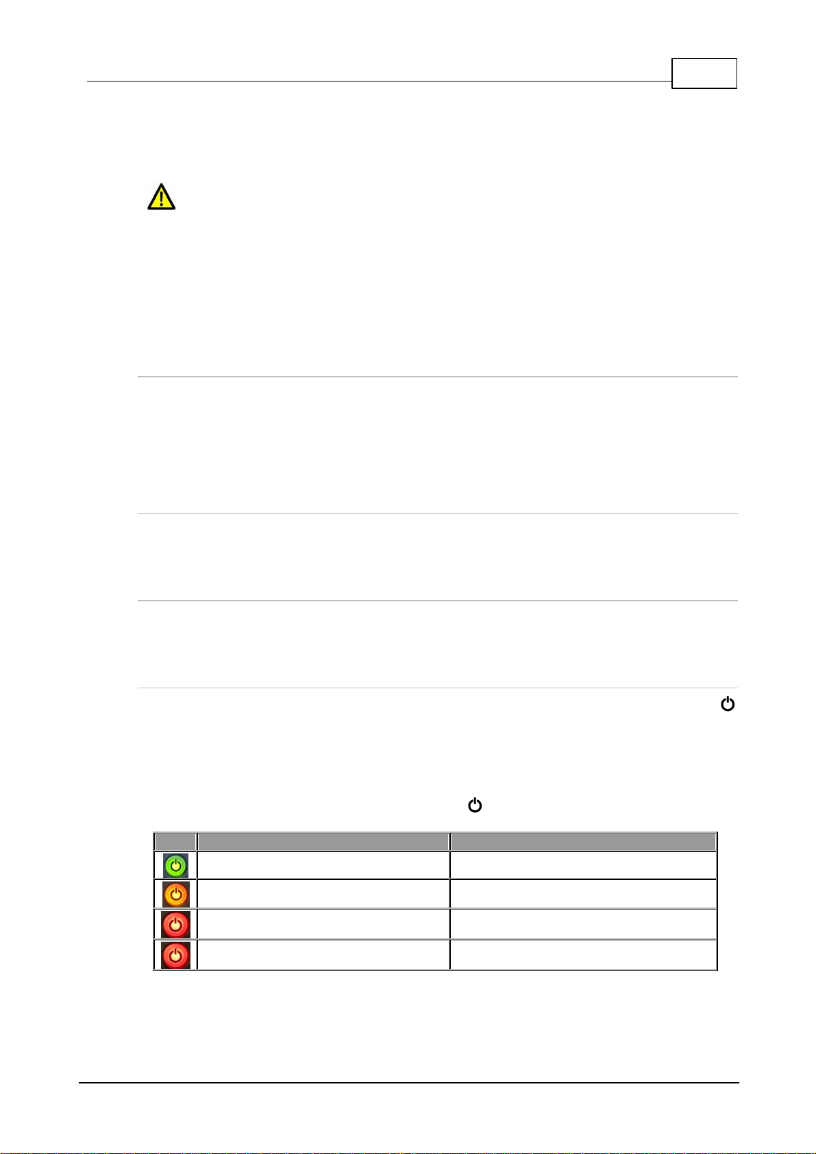
LED Indi cation
Battery Sta te
GREEN LED (Solid)
Battery level is between 21 - 100 %
ORANGE LED (Solid)
Battery level is between 11 - 20 %
RED LED (Solid)
Battery level is between 6 - 10 %
RED LED (Flashing)
Battery level is 5% or lower
ViA has an internal battery slot on the rear panel designed for high performance RRC2057 Lithiumion batteries. Only use this battery in the codec.
Inserti ng the Battery
1. Push dow n on the BATTERY CASE CLIP to open the lid to the battery c ompartment.
2. Inser t the BATTERY c arefully and ensure t he grooves at the bott om of the BATTERY li ne up
correctly with the bottom of the BATTERY COMPARTMENT. Note: It s hould slide in sm oothly .
3. Repla ce the BATTERY CASE CLIP carefully by lining up the t wo protruding plastic lugs with t he
base of the compartment, then push the center of the BATTERY CASE CL I P t o c l os e it fully.
ViA User Manua l v1.2
15
Removing the Batt ery
1. Push dow n on the BATTERY CASE CLIP to open the lid f o r the BATTERY COMPARTMENT.
2. Pinch the tag on the BATTERY to pull it slowly out of the BATTERY COMPARTMENT.
Charging the Batter y
When the power supply is connected to t he codec's P OWER SOCKET it will charge the internal
BATTERY in less t han 4 hrs.
Battery Indications
The battery has a c harge s tatus butt on to verify its c harge state when it is [ON]. The POWER
button is green when the power supply is connected to the codec's power s oc ket. W hen the c odec
is operating on battery power it provides the following battery level indications:
1. The Battery symbol and char ge remaining is visible in the Status Bar in the top right c orner
of the TOUCH SCREEN.
2. When operating on battery pow e r the POWER button indications are as follows:
© Tieline Pty. Lt d. 2016
16 ViA User Manua l v1.2
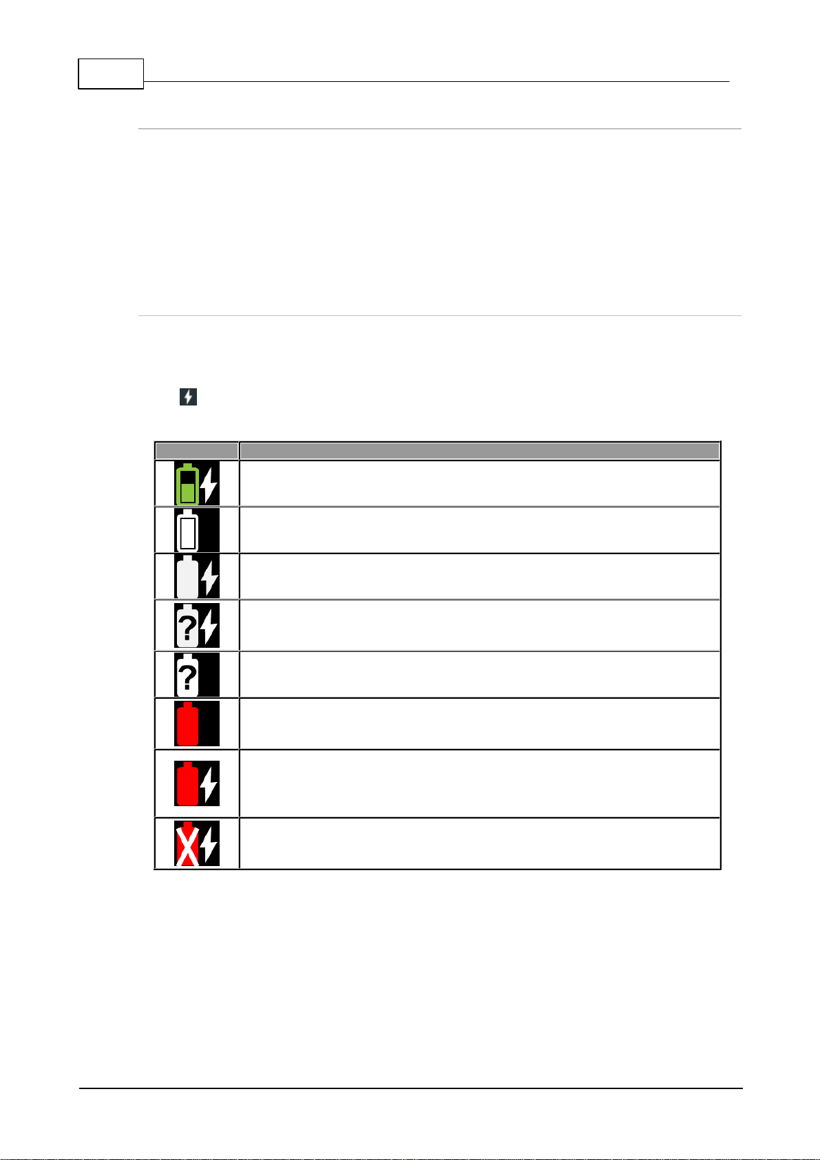
Symbol
Battery Sta te
Power is attached to the codec and the battery is c harging.
The battery is fully charged and no power is at t ac hed to the c odec.
The battery is fully charged and the external power supply is i n use.
Unknown battery error while the external power supply is attac hed. The battery
should immediately be removed from the c odec. Please c ontact Tieline if this
sit uation persist s.
Unknown battery error. The batt ery should im mediately be removed from t he
codec. P l ease c ontac t Tieline if this situation persist s .
The battery is too hot or too cold. Move the codec to a cooler or warmer
location as required.
An external power supply is attached and the battery is too hot or too cold and
not charging. For safety reasons, the battery is prevented from charging if t he
internal temperature is above or below pre-set thresholds. M ove the codec to a
cooler or warmer location as required, to allow the battery t o c ontinue charging.
The battery has overheated or is dead. For safety reasons the battery is
prevented from charging, or discharging and powering t he codec. The battery
should be removed from the codec and allowed to cool.
Low Battery Headphone Al ar m Tones
A low battery alarm is audible in the headphones when the battery level reaches 20%, 10% and 5%.
1. Alarm tones are audible in the left headphone output of HP 1-3.
2. A warning dialog is displayed on the TOUCH SCRE EN until ac knowledged.
3. The ALARM LED flas hes until ac k nowledged, and then turns solid red.
T ap the TOUCH SCREEN or touch any codec c ontrols t o ack nowledge the alarm and st op the alarm
tones.
Touch Screen Battery Indicati ons
The percentage of battery c harge remaining is dis played next to the batt ery s ymbol in t he Status
Bar on the TOUCH SCREEN. In addition:
· When power is att ached t o t he c odec t he BATTERY sym bol is green and the white Power
sy m bol is displayed.
· When operating on battery power the BATTERY symbol is white.
© Tieline Pty. Lt d. 2016
ViA User Manua l v1.2
17
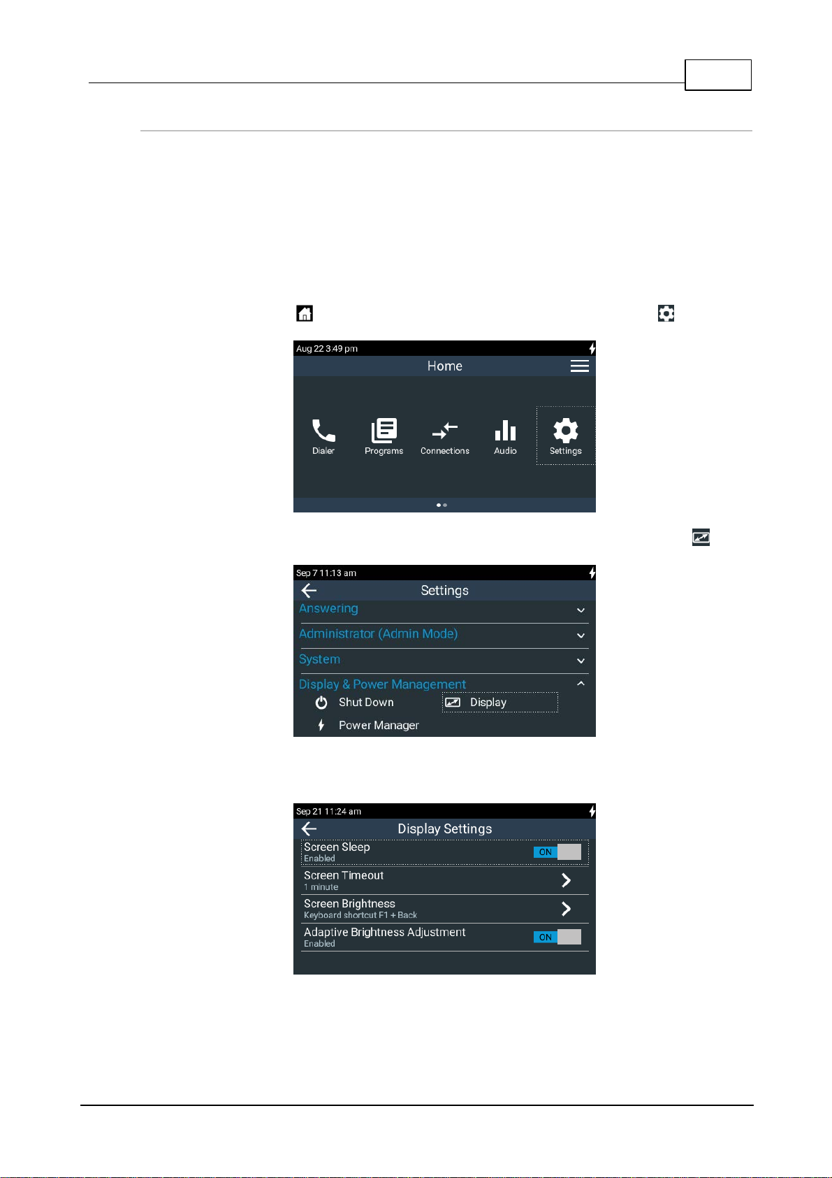
Touch Screen Power Management
By default the TOUCH SCREEN has Scre en Sl ee p m ode enabled to preserve battery power. The
default Scre en Ti meout setting is 1 m inute. T h e TOUCH SCREEN will "reawaken" from sleep
mode when a button or rotary encoder is adjusted, or the TOUCH SCREEN is tapped or swiped. It is
also possible t o:
· Adjust Screen Brightne ss.
· Enable Adaptive Brightness Adj ustment.
To adjust these s et t i ngs:
1. Press the HOME butt on to return to the Home screen , then tap Settings .
2. T ap to expand the Displ ay a nd P owe r M ana gement menu and then tap Display .
3. T ap the On/Off button to toggle between enabling and disabling Screen Sleep (default
setting On).
4. Tap Scree n Time out to adjus t the number of m inutes , then tap Accept in the top
© Tieline Pty. Lt d. 2016
righ t-ha nd corner of the TOUCH SCREEN.
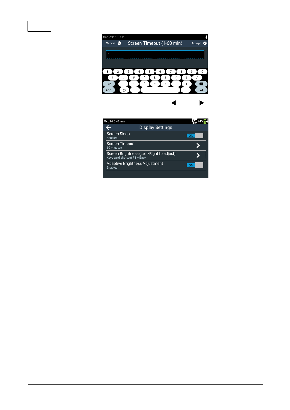
18 ViA User Manua l v1.2
5. Tap Screen Brightne ss and th e n use the left and right NAVIGATION buttons to
adjust brightness.
6. T ap the On/Off button to t oggle between enabling and dis abling Adaptive Brightness
Adjustment (defa ult setting On).
© Tieline Pty. Lt d. 2016
ViA User Manua l v1.2
Power M ana gement Mode
Explanation
Audio Power Setting
(def ault setting High)
Power consumption can be reduced by lowering the
audio outpu t threshold fr om +22d BU to +16dBU. Tap
Audio Powe r S etting to make this adjustment
Low Battery Screen Power Saving
(def ault setting On)
This feature is ac t ivated when the battery c harge level
is 15%. Th e TOUCH SCREEN brightness is reduced
and 's l eep mode' is enabled with a 1 mi nute t im e-out.
T his setting overrid es the Screen Ti m eout set ting in
the Display menu. Note: When power i s applied
to the codec this feature is overr idden.
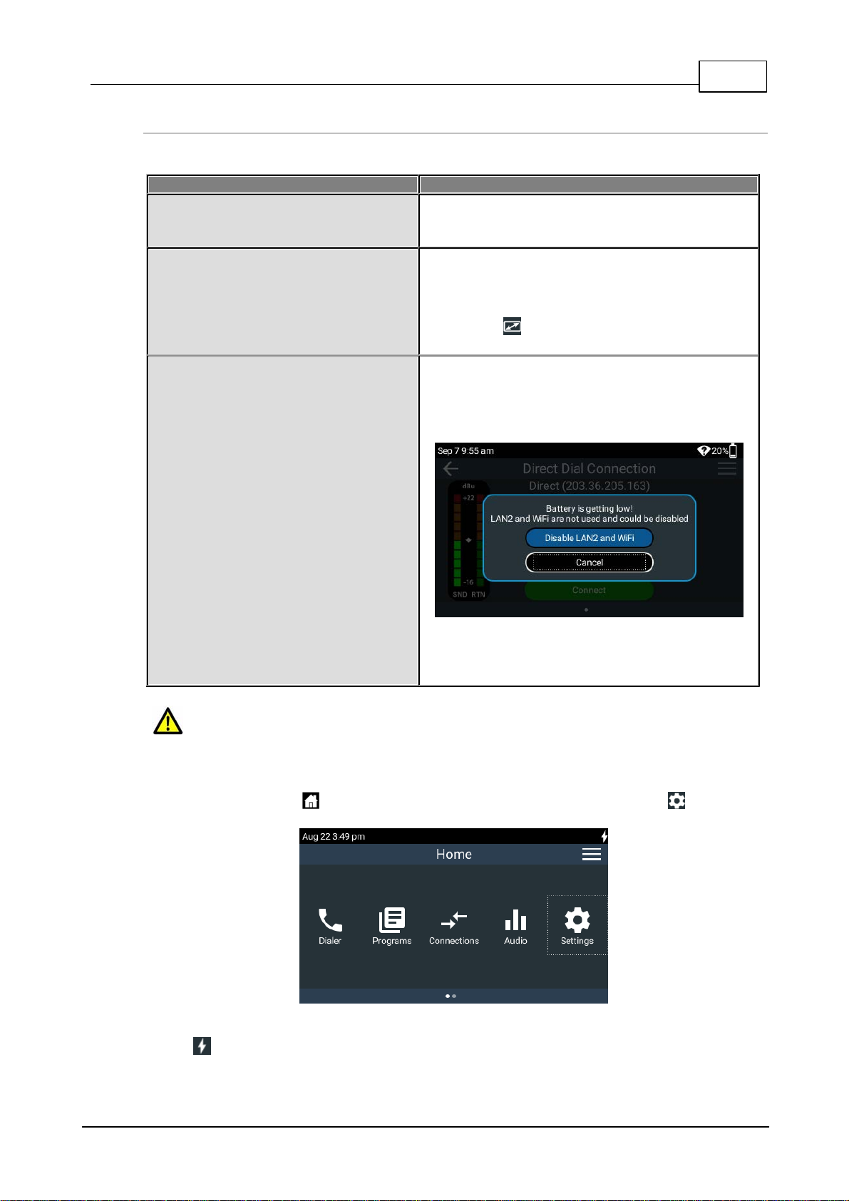
Low Battery Network Powe r Saving
(def ault setting On)
This feature is ac t ivated when the battery c harge level
is 20%. The codec launches a dialog s uggesting any
unused network interfaces be disabled to conserve
power.
If LAN2 is being used and LAN1 is inactive, a dialog
will appear and suggest s witching to LAN1 as this
consumes l es s power.
Caution: Low power mode lowers t he threshold at which audio will distort. Ensure audio
levels do not exceed +16dBU in this mode of operation.
19
Advanced Power Management
Other ways t o conserve battery power when operating without a power supply inc lude the following:
To adjust these s et t i ngs:
1. Press the HOME button to return to the Home screen, then tap Settings .
2. T ap to expand the Displ a y a nd P ow er Mana ge m ent menu and then tap Pow e r Ma na ger
.
© Tieline Pty. Lt d. 2016
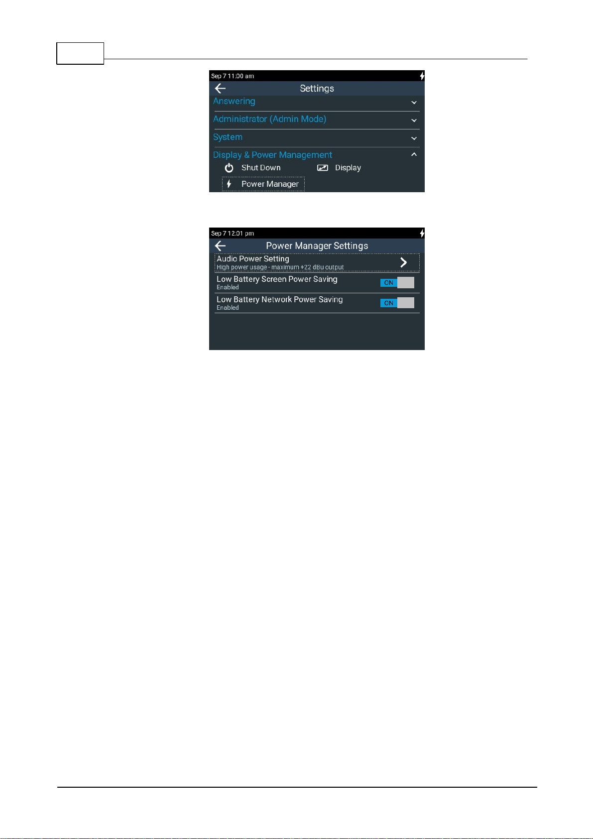
20 ViA User Manua l v1.2
3. Tap to adjust each option.
© Tieline Pty. Lt d. 2016
7 Inserting and Removing Modules
ViA code c with an ISDN modul e i nstalled
Ensure the codec is not powered up when inserting or removing modules. Where possi ble
use anti-st atic precautions to help minimiz e the c hance of static charges damaging the
highly sensit i ve circuit ry . Do not force a module into the codec. Modules s hould be installed
slowly and gently.
A s ingle module slot is available on the codec rear panel for ins erting an opti onal ISDN or POTS
module into the codec.
Inserti ng or Removing a Module
ViA User Manua l v1.2
21
1. Press the POWER button and tap Shut Dow n to turn the code c [OFF].
2. Remove the 4 screws from the blanking panel or module installed in the codec.
3. Carefully s lide the new module into the module slot and ensure t he base of t he module remains
flat during insertion, to ensure it lines up correctly with t he module connector in the codec.
4. Reinsert the 4 screws to hold the module fi rmly i n place.
5. Press the POWER button to power up the codec.
6. Press the HOME button to return to the Home screen an d tap Settings .
7. Tap Tra nsport Interface s t o ex pand the m enu and tap IS DN Module or POTS Module to
configure module sett i ngs.
© Tieline Pty. Lt d. 2016
22 ViA User Manua l v1.2
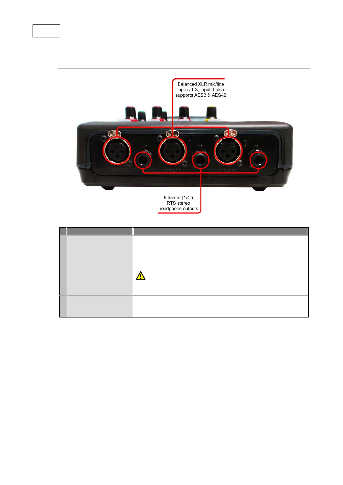
Connection
Details
1
Analog XLR, AES3 and
AES 42 Inputs
XLR inputs 1-3 are all balanced mic /line inputs. Input 1 can als o be
used as an AES3 (AES/EBU) digital input, which accepts both
mono and stereo digital AES3 signals. Alternatively, input 1 also
supports AES 42 Mode 1 and Mode 2 mics . AES input modes can
be selected via codec menus.
VOLTAGE WARNING: DO NOT att ac h non-digital mic rophones
or an AES3 source to input 1 when AES42 mode is selected, or
equipment may be damaged by high voltages.
2
Headphone Outputs
The codec has three 6.35mm (1/4") RTS st ereo headphone outputs
labeled as HP 1 - 3. These are designed to be used with 600 ohm
headphones.
8 Externa l Connec tions
Front Panel Connections
© Tieline Pty. Lt d. 2016
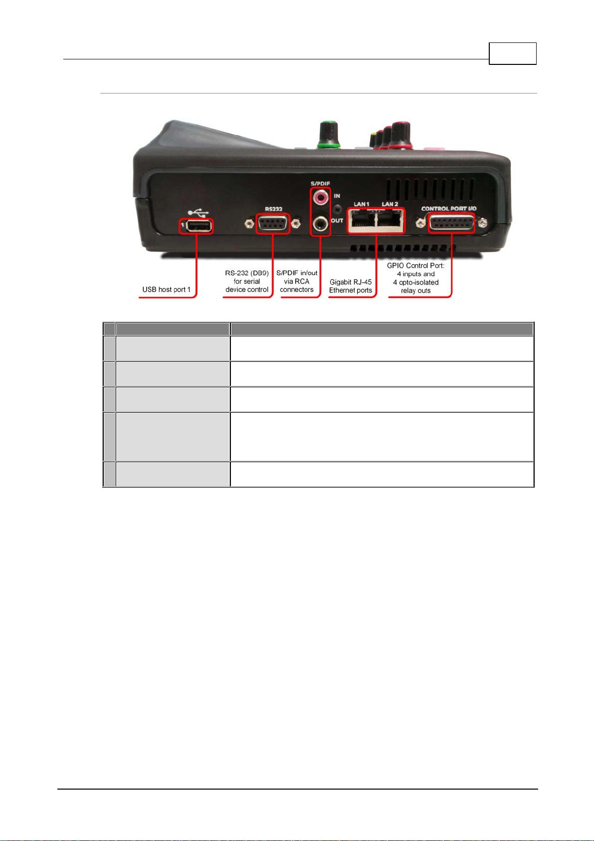
Left Side Panel Connecti ons
Connection
Details
1
USB Port 1
USB host port 1 for at tachment of a supported cellular m odem for
data connections. A l so supports at t ac hment of a USB key board.
2
RS232
Nine pin female RS232 serial data connection for local and remote
control of equipment at either end of the link.
3
S/P DIF In/Out (Auxil iary
input)
S/P DIF I N/OUT auxiliary input and output via RCA connectors.
4
LAN1 and LAN2 Ports
The codec features two Gigabit (10/100/1000) RJ-45 Et hernet ports
for IP connections. By default, the codec ass umes LAN1 is the
primary LA N connection and LAN2 is t he backup (secondary) LAN
connection when in use.
5
Control Port I/O
Four relay inputs and four opto-isolated outputs for machine control
v ia the DB15 CONTROL PORT I/O connector.
ViA User Manua l v1.2
23
© Tieline Pty. Lt d. 2016
24 ViA User Manua l v1.2
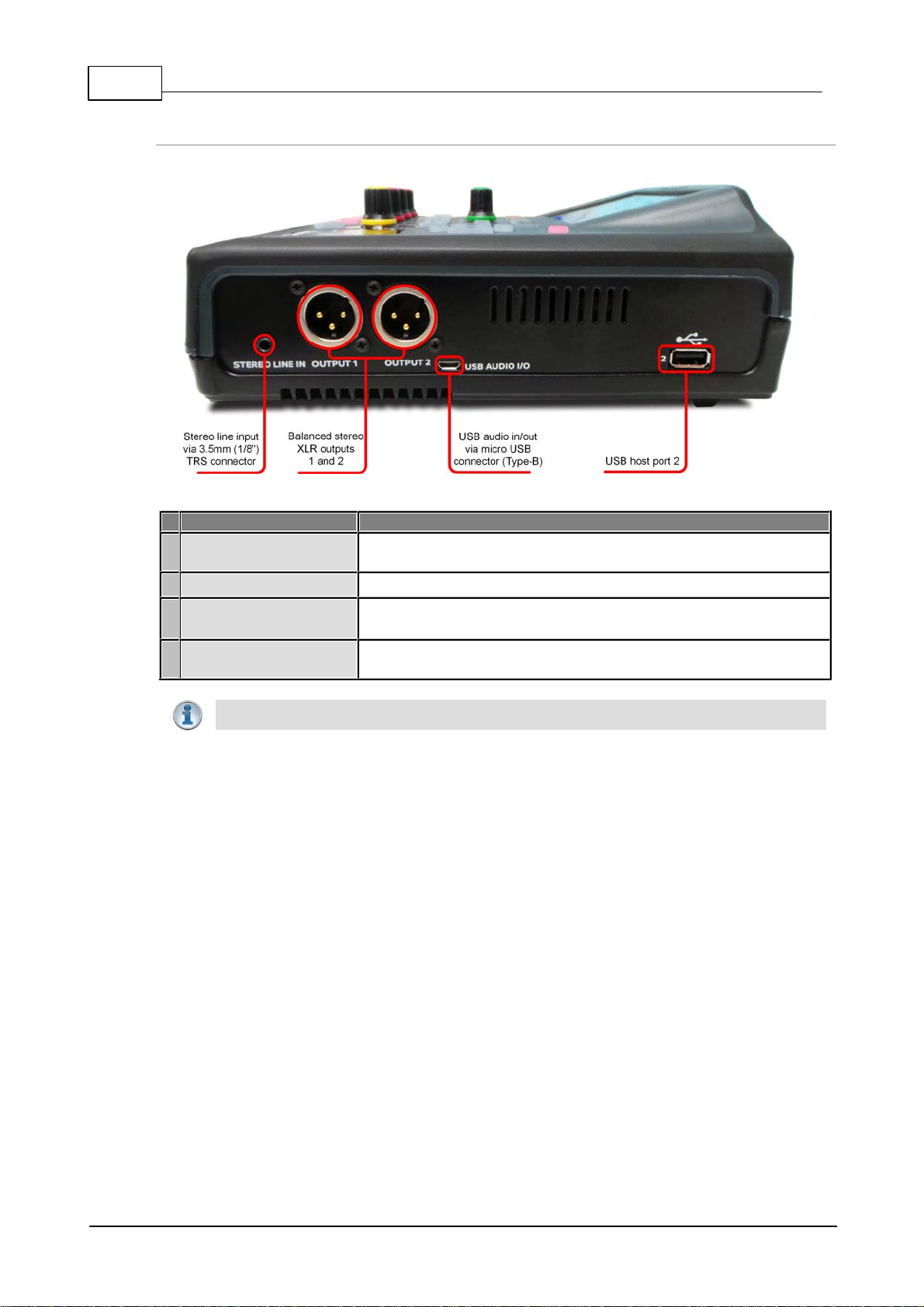
Connection
Details
1
Stereo Line In
STEREO LINE IN is an auxiliary line input opti on via a 3.5mm (1/8")
TRS connector.
2
Outputs 1 and 2
OUTPUT 1 and 2 are balanced analog XLR line outputs .
3
USB Audio I/O
USB AUDI O I/ O is an auxiliary input/output option via a m icro
USB Type -B conn ector.
4
USB Port 2
USB host port 2 for at tachment of a supported cellular m odem for
data connections. Also s upports att achment of a USB key board.
Impo rta nt Note: Only one auxiliary input option can be select ed at a tim e.
Right Side Panel Connections
© Tieline Pty. Lt d. 2016
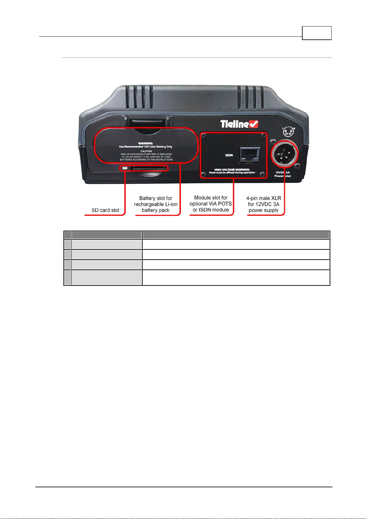
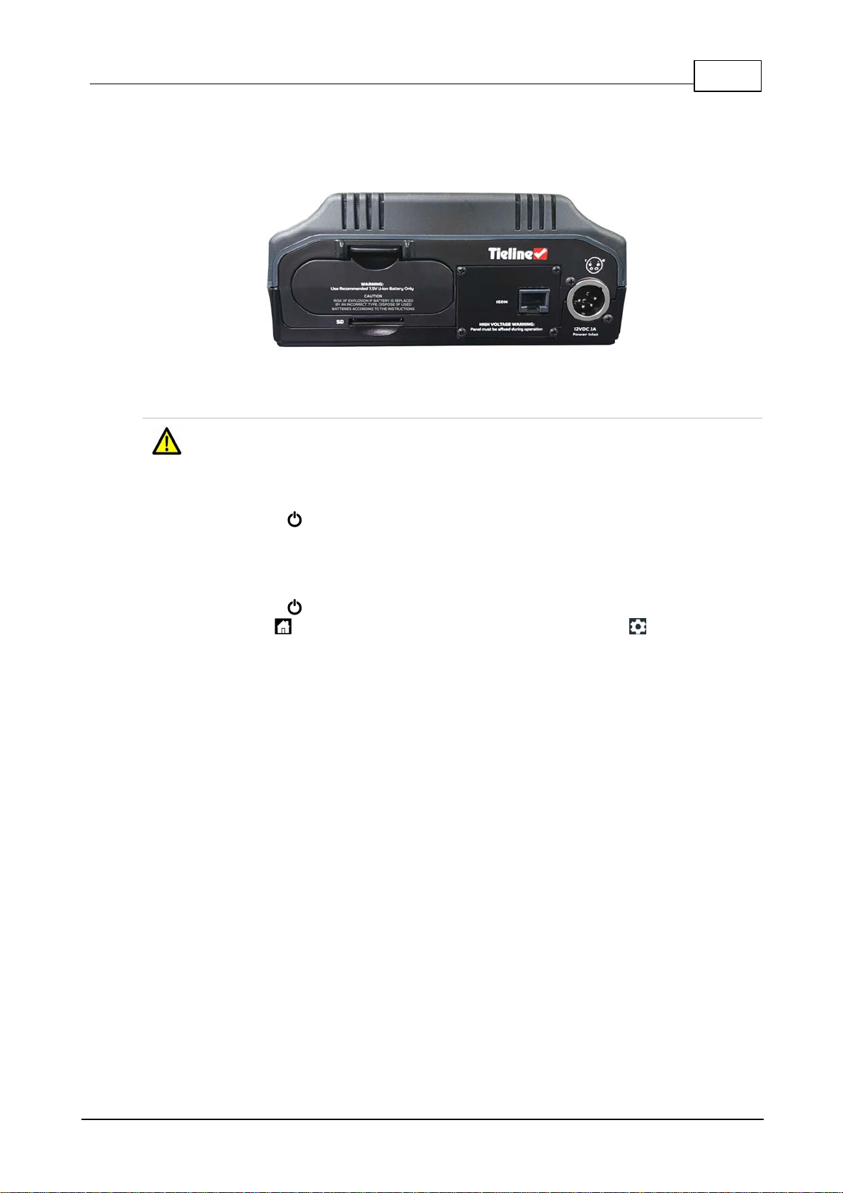
Rear Panel Connections
Connection
Details
1
Battery s l ot
Battery s l ot for RRC2057 rechargeable Li-ion battery pack.
2
SD Card slot
SD card slot for file playback*
3
Module slot
Module slot for inserting an optional ViA POTS or ViA ISDN module.
4
XLR Power Socket
4-pin male XLR on the rear panel t o attac h an ex ternal 12VDC 3A
power supply.
ViA User Manua l v1.2
25
* Feature in future release
© Tieline Pty. Lt d. 2016
26 ViA User Manua l v1.2
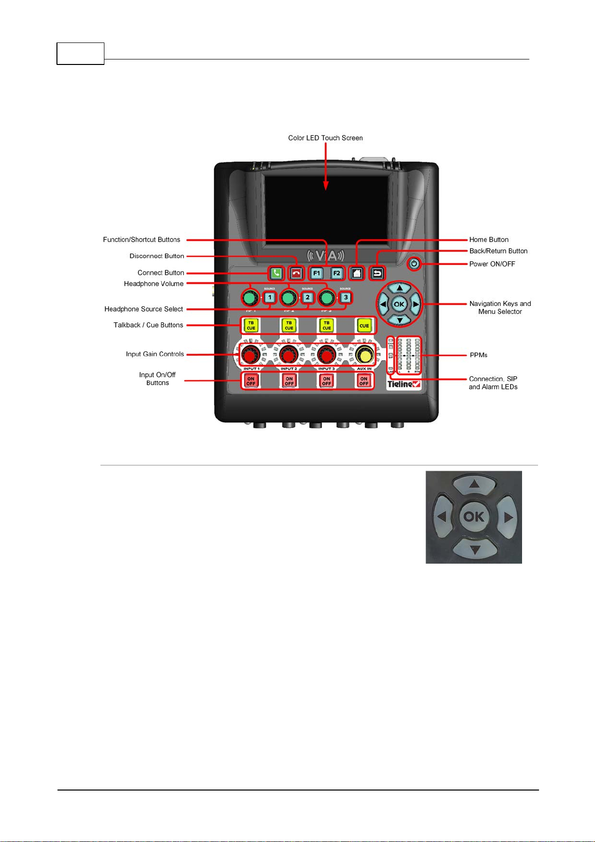
The codec has four arrow shaped navigation buttons for navigating
codec menus and adjust ing levels and sett ings. The OK button is
used to select menu items .
9 Codec Con trols
The top of the codec features input and headphone c ontrols, as well as navi gation buttons, a color
LCD TOUCH SCREEN display and PPM met ers.
Navigation Buttons
© Tieline Pty. Lt d. 2016
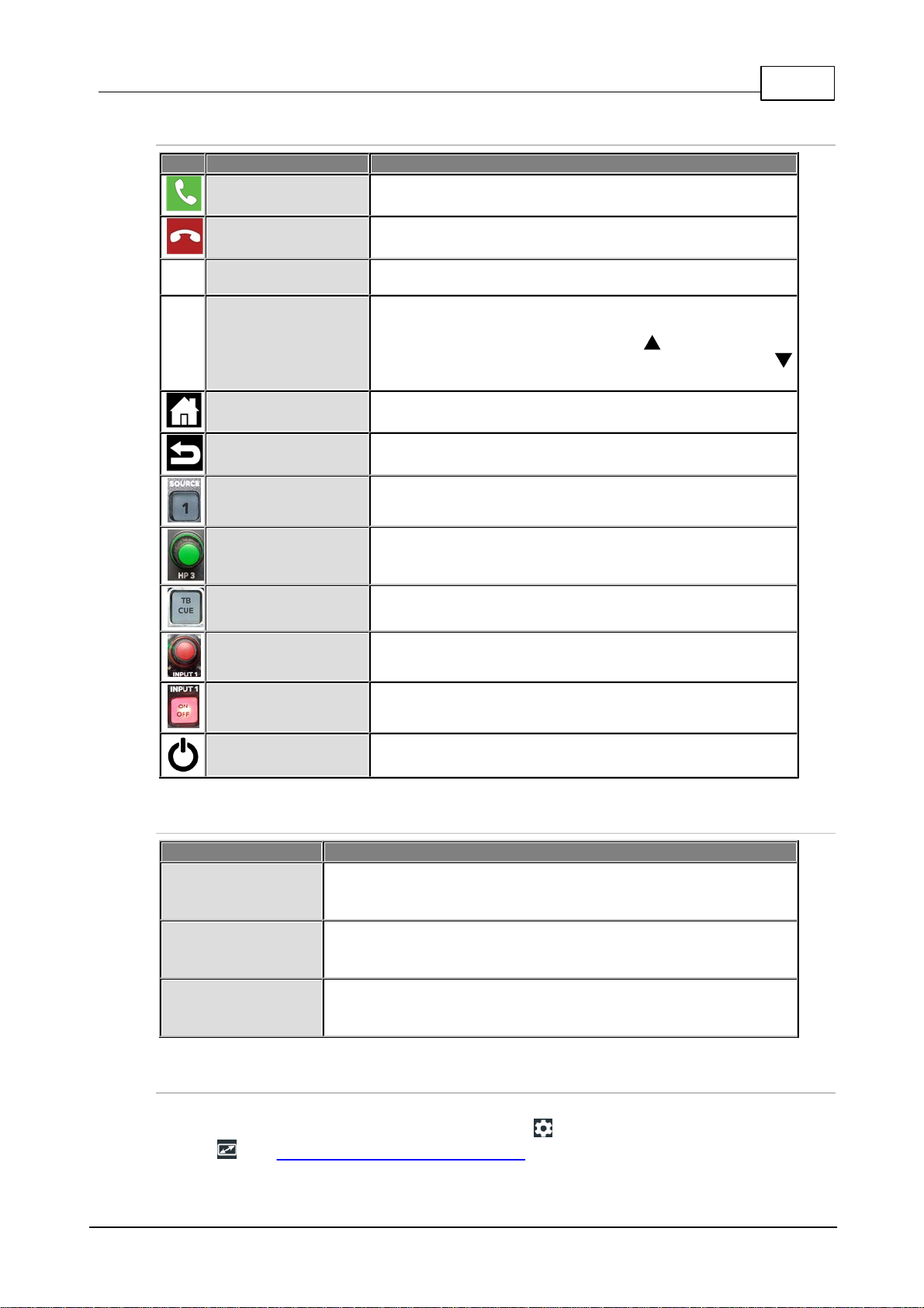
Operati on Button Descriptions
Features
Operation Button Descri ptions
Connect B ut t on
Press to dial/connect
Disconnect B ut t on
Press to disconnect a c onnecti on
F1
Function Butt on 1
Press to activate codec user functions
F2
Function Butt on 2
Press to activate codec user functions. Negotiate higher
connection bit rates in t he Statistics screen by pressing the
F2 button and then the NAVIGATE UP butt on; for lower bit
rates press the F2 button and then the NAVIGATE DOW N
button.
Home Button
Press to return to the Home screen
Back /Return Butt on
Press to move back through menus & delete c haracters
Headphone Source
Select B utton
Press to adjust headphone send/return balance, or select
headphone monitoring sources
Headphone Volume
Adjusts the headphone level for each headphone output
TB/Cue Butt on
Supports us er talk back, or cue source monitoring modes
Input Gain Control
Adjusts mic/li ne input gain for inputs 1 - 3 and the auxil iary
input
Input On/Off
Press to turn each input on or off
Power On
Press to turn the codec on; press and tap Shut Dow n t o turn
the codec [OFF], Reboot or enter Screen Sl ee p mode.
LED
LED Description
CXN (Connect ion)
When dialing a connection the CXN LED flashes until the codec
connects. Note: It also flashes until all streams/transports are
connected when multiple s t reams/ t ransports are connecting.
SIP
The SIP L ED flashes orange when registering to an active SIP s erver
account. It illuminates solid orange when the codec has been
registered to an active SIP account successfully.
Alarm
The ALARM LED flas hes red when an alarm is act ive in the c odec. It
stops flashing and illuminates solid red after an alarm has been
acknowledged.
ViA User Manua l v1.2
27
Front Panel LED Descriptions
Touch Screen Sleep Mode
By default the codec TOUC H SCRE EN will enter 'sleep mode' after a minute of inacti vit y. To adjust
this s et t i ng go t o the Home scree n and tap Settings > Display a nd Pow e r Ma nage me nt >
Display . See Bat t ery Us e and Power Management for more info.
© Tieline Pty. Lt d. 2016
28 ViA User Manua l v1.2
10 Wireless IP Connection Options
The codec has multiple IP interface connect ion options, inc l uding:
1. LAN1 Ether net port (def au lt Primary Via interface in the Dialer )
2. LAN2 Ether net port (def au lt Secondary Via interface in the Dialer )
3. Inter nal Wi-Fi (de f ault Tertiary Via interf a ce in the Dialer )
4. External USB PORT 1.
5. External USB PORT 2.
Use the Select Via interfaces s creen in t he Dialer to choose the interface used when
establis hing a connection. By defau lt Any is selec ted, which means the first available interface will
be used to dial a connection. To connect over a LAN, att ach an E thernet c able to eit her LAN1 or
LAN2 on the codec.
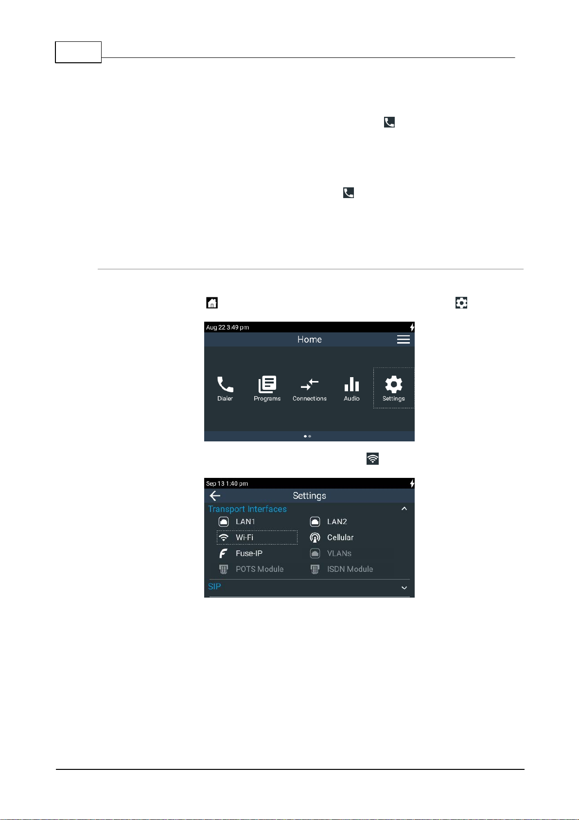
Connecting a Wi - Fi A ccess Point
To connect the c odec t o a W i -Fi network acc es s point:
1. Press the HOME button to return to the Home screen, then tap Settings .
2. T ap to select Tran sport Interface s and then tap Wi-Fi .
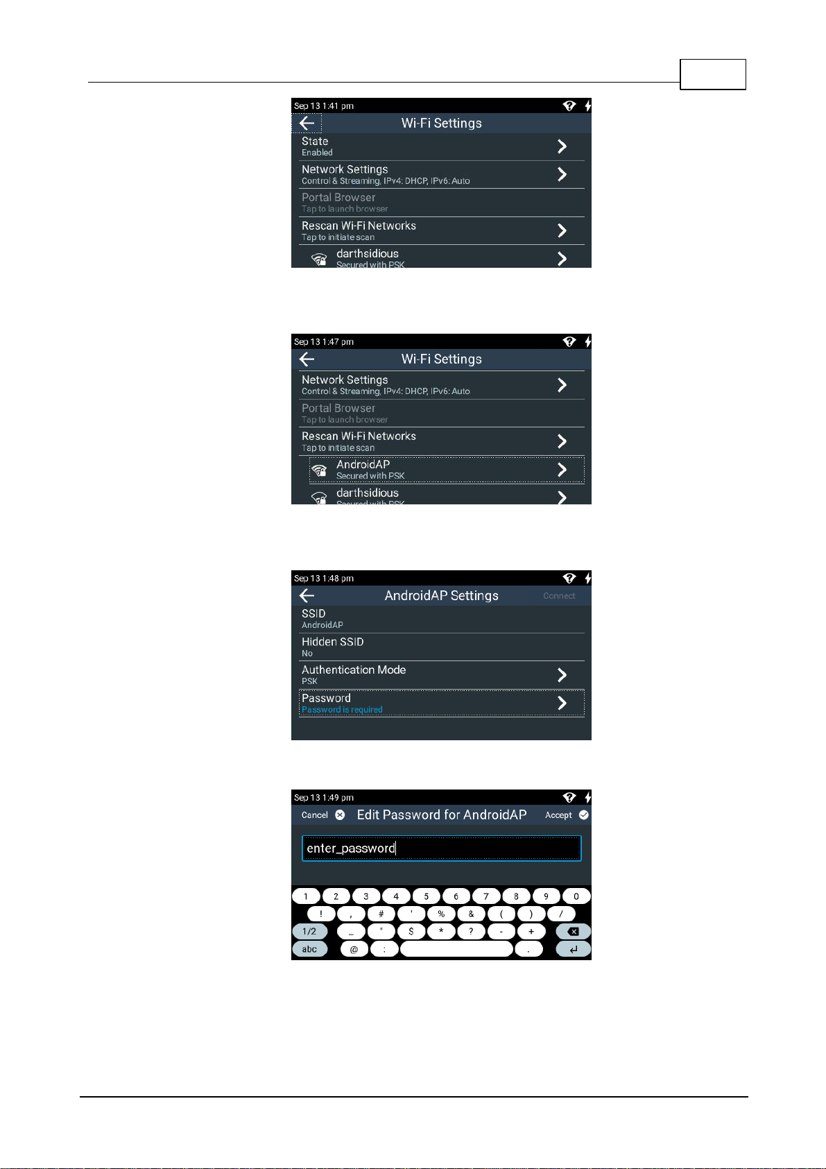
3. Ensure the Wi-Fi State is Enabled and tap Re scan Access P oints i f the required Wi-Fi
network is not populated in the acces s point list.
© Tieline Pty. Lt d. 2016
ViA User Manua l v1.2
29
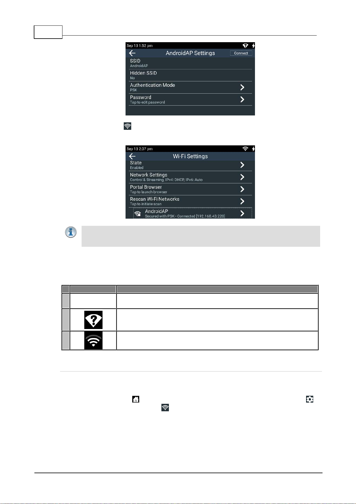
4. Tap to select the Wi-Fi access point to which you are connecting, in this example
AndroidAP.
5. Tap t o select t he preferred Authenticatio n Mode and t hen tap Password to enter the
network pass word.
6. Enter the password, then tap Accept in the top right-hand corner of the TOUCH SCREEN.
7. Tap Connect in t he top right-hand c orner of the TOUCH SCREEN to connect to t he W i-Fi
© Tieline Pty. Lt d. 2016
network.
30 ViA User Manua l v1.2
Impo rta nt Note: Vi A supports IEEE 802.11 a/b/g/n W i -Fi with dual band connectivity (2.4
and 5 GHz). For increased security Tieline has im plemented the WP A2-PSK
authentication protocol because standard WEP encry pti on is les s sec ure.
Symbol
Description of Status
1
No symbol
displayed
Wi-Fi i s dis abled in the codec
2
· Wi-Fi i s enabled in the codec, but it i s out of range of a Wi-Fi network, or
· The codec is within range of a Wi -Fi network, but is either not c onnected
or is in the process of connecting
3
The codec is connected to a Wi-Fi network and signal strength is display ed
8. Verify the Wi-Fi symbol is visible in the Status Bar t o confirm the codec has connected
to the W i-Fi ac cess point.
Wi-Fi Indications
T he following Wi-Fi indications are displayed in the Status Bar on the codec s creen.
Browser Wi - Fi Login
Some Wi-Fi networks require a browser to log i n and connect to the acc ess point, e.g. hotel Wi -Fi
networks . To log in to this type of network:
1. Press the HOME button t o return to t he Home screen, then tap Settings >
Transport Interfaces > Wi-Fi .
2. Tap to select the network to which you are connecting.
© Tieline Pty. Lt d. 2016
 Loading...