

Tieline Commander TLF200, Commander TLR200 Operation Manual

TLF200/TLR200 POTS CODEC
Operation Manual
For Software Version 2.205

COMMANDER WELCOME
©Tieline Technology - 2 - August 2002
TLF200
TLR200
COMMANDER Features
¾ Two balanced Microphone/Line inputs; Standard XLR three-pin female.
¾ Optional ISDN Interface.
¾ Choice of a Compact Field unit or a Studio (rack mount) unit.
¾ LED Peak Program level meter (–12dBu to +16dBu).
¾
A cell phone jack (3.5mm) is provided for standard bi-directional phone quality audio.
¾ Two CMOS relay facilities are provided via 3.5mm jacks for remote control of
equipment.
¾
Optional Data Streaming for data link applications.
The COMMANDER has the same software upgrade capabilities as all other Tieline
Codecs. Full upgrades are possible using the Tieline Toolbox software.
We are continually updating our manuals and software…Get the latest at;
www.tieline.com.
IMPORTANT!
Register on our website as a Tieline user and get notification of new software

COMMANDER WARRANTY
WARRANTY
WARRANTY
TIELINE TECHNOLOGY (Manufacturer) warrants that this product is free of defects in both
materials and workmanship.
Should any part of this equipment be defective, the Manufacturer agrees, at its option, to:
a) Repair or replace any defective part free of charge (except transportation charges) for a
period of one year from the date of the original purchase, provided the owner returns
the equipment to the Manufacturer. No charge will be made for parts or labor during this
period or
b) Furnish replacement for any defective parts in the equipment for a period of one year
from the date of original purchase. Replacement parts shall be furnished without
charge, except labor and transportation.
This Warranty excludes assembled products not manufactured by the Manufacturer
whether or not they are incorporated in a Manufacturer product or sold under a
Manufacturer part or model number.
THE WARRANTY IS TERMINATED WHEN ANY OF THE FOLLOWING HAS
OCCURRED TO THE EQUIPMENT:
a) Damage by negligence, accident, act of God, mishandling, or it has been operated
incorrectly to the various instructions described in the Operation Manual.
b) Altered or repaired by other than the Manufacturer or an authorized service
representative of the Manufacturer.
c) Any adaptations or accessories other than those manufactured or provided by the
Manufacturer have been made or attached to the equipment, which, in the determination of
the Manufacturer, shall have affected the performance, safety or reliability of the
equipment.
d) The original serial number has been modified or removed.
NO OTHER WARRANTY, EXPRESS OR IMPLIED, INCLUDING WARRANTY OF
MERCHANTABILITY OR FITNESS FOR ANY PARTICULAR USE, APPLIES TO THE
EQUIPMENT, nor is any person or company authorized to assume any warranty for the
Manufacturer or any other liability in connection with the sale of the Manufacturer's
products.
Manufacturer does not assume any responsibility for consequential damages, expenses, or
loss of revenue or property, inconvenience, or interruption in operation experienced by the
customer due to a malfunction in the purchased equipment.
No warranty service performed on any product shall extend the applicable warranty period.
In case of unsatisfactory operation, the purchaser shall promptly notify the Manufacturer in
writing, giving full particulars as to the defects or unsatisfactory operation. Upon receipt of
such notice, the Manufacturer will give instructions respecting the shipment of the
equipment, or such other matters as it elects to honor this warranty as above provided.
This warranty does not cover damage to the equipment during shipping and the
Manufacturer assumes no responsibility for such damage. The customer shall pay all
shipping costs.
This warranty extends only to the original purchaser and is not assignable or transferable.
Subject to change without notice

COMMANDER TABLE OF CONTENTS
Table of Contents
WARRANTY ..........................................................................................................3
INSTALLATION AND USAGE TIPS ......................................................................7
CONTROLS & CONNECTIONS............................................................................8
Field Unit TLF200 ............................................................................................................................. 8
Rack Unit TLR200 ............................................................................................................................ 9
QUICK START GUIDE for the Beginner..............................................................10
Operating the Menu Selector (MS)................................................................................................. 10
Setup for Microphone Input ............................................................................................................ 10
GETTING STARTED...........................................................................................12
Setting Factory Defaults ................................................................................................................. 12
Dialing a number............................................................................................................................. 13
Dialing From an Office or Hotel Room............................................................................................13
Handset Dialing .............................................................................................................................. 14
Memory Dialing from Interstate or International call areas............................................................. 14
How to store a phone number ........................................................................................................ 15
FUNCTION KEYS................................................................................................17
Quick Function Tips ........................................................................................................................ 17
Default Function Keys..................................................................................................................... 17
Function Key Options ..................................................................................................................... 18
DETAILED CONFIGURATION ............................................................................20
Setup Menu .................................................................................................................................... 20
Sub Menus of 01 – View Configuration .......................................................................................... 22
Sub Menus of 02 – Codec Setup.................................................................................................... 26
Sub Menus of 03 – Modem setup...................................................................................................27
Sub Menus of 04 – Dialing setup.................................................................................................... 28
Sub Menus of 05 – Unit Setup........................................................................................................ 29
Sub Menus of 06 – ISDN Setup ..................................................................................................... 30
Sub Menus of 07 – Advanced Setup .............................................................................................. 31
Sub Menus of 08 – Timer Functions...............................................................................................32
Sub Menus of 09 – Reset Functions .............................................................................................. 33
Sub Menus of 10 – Test Modes...................................................................................................... 33
Sub Menus of 11 – Memory Setup ................................................................................................. 33
Sub Menus of 12 – Unit Details ...................................................................................................... 33
HOW THE COMMANDER WORKS.....................................................................34
Theory of Operation........................................................................................................................ 34
Peak Level Meter............................................................................................................................ 34
Modem Negotiation and Line Quality ............................................................................................. 35
Master Slave Operation.................................................................................................................. 35
ISDN Operation .............................................................................................................................. 36
Relay Control .................................................................................................................................. 36

COMMANDER WELCOME
©Tieline Technology - 5 - August 2002
TOOLBOX Software ............................................................................................38
Preparing to use the ToolBox application....................................................................................... 38
Connecting COMMANDER to the PC ............................................................................................ 38
Menu Items ..................................................................................................................................... 39
General Configuration..................................................................................................................... 41
POTS Setup.................................................................................................................................... 41
Local Control................................................................................................................................... 42
Remote Control............................................................................................................................... 43
Line Monitor .................................................................................................................................... 43
Chat ................................................................................................................................................ 44
Phone Book .................................................................................................................................... 45
Functions ........................................................................................................................................ 46
Software Upgrade........................................................................................................................... 47
Mic / Line Audio In Connector ........................................................................................................ 48
Program Out Connector ................................................................................................................. 48
RS 232 Interface Connector ........................................................................................................... 48
TIELINE CODEC SOLUTIONS FAMILY..............................................................49
COMPLIANCES...................................................................................................50
INDEX..................................................................................................................52

COMMANDER INTRODUCTION
INTRODUCTION
Thank you for buying a Tieline technology codec!
In the audio codec broadcast revolution Hearing is believing….
Tieline, providers of the world’s best Plain Old Telephone Service (POTS) Codec
technology, developed the COMMANDER codec to provide high quality, bi-directional
audio for POTS together or ISDN operation.
Tieline has changed the opinions of even the most critical broadcasters, proving that
stable high bandwidth links with unfailing audio and data is the new reality for
broadcasting over a telephone line.
A superb DSP algorithm delivers crystal clear 15kHz bi-directional audio in real time at bit
rates as low as 24kbps with a small 100ms delay and a minimal loss of quality over a
standard telephone line.
COMMANDER is the versatile CODEC solution, giving you full broadcast freedom with
the ability to use ISDN if required. COMMANDER is part of the Audio Codec Family that
includes the PATRIOT – the economical solution and i-Mix – the Sportscasters Dream
Machine.
COMMANDER provides audio-link opportunities previously that were impossible or
simply too expensive to use. Broadcast journalists and presenters now have an easy to
use compact portable field codec with high quality, two-way audio link performance.
COMMANDER can be transported as carry-on baggage allowing convenient worldwide
coverage with minimal equipment or is available as a professional Studio rack mount
unit.
Using the COMMANDER is as simple as plugging it into a POTS (Plain Old Telephone
Service) or ISDN (optional extra) phone line and dialing the destination number. The
receiving Tieline codec automatically answers the call and establishes the link. For POTS
connections, a built-in modem negotiates the best possible data rate for high-quality lownoise and distortion, bi-directional audio.
COMMANDER features include:
• High quality audio at very low bit rates
• ISDN as an optional extra
• Many remote control features for remote operation
• Purpose built modem for POTS codec operation
• Automatic link re-connect in the event of line dropouts
• Extensive menu system caters for most individual applications
• Choice of optional extras such as;
o 15kHz audio in one direction and up to 9600bps in the opposite direction
OR
o 7kHz audio and up to 4800bps of data simultaneously in both directions
• Fast and easy configuration via a Windows 9*/ME/2K software application:
Toolbox

COMMANDER INSTALLATION AND USAGE TIPS
INSTALLATION AND USAGE TIPS
While the TIELINE COMMANDER is a very reliable telecom product, its performance will only be
as good as the line that it is operating over.
Proper precautions MUST be taken to ensure that only the COMMANDER uses the line.
Remove these possible interference sources:
• Other telephone handsets
• Fax machines
• Computer modems
• Alarm systems
• Extension bells
• Line monitoring devices
Important precaution for the COMMANDER phone-line:
ENSURE THAT CALL WAITING IS DISABLED!
It is always preferable to obtain a dedicated phone line from the local Exchange or Central Office.
Try to avoid going through a PBX, PABX, Key station or any other local exchange. If this is
unavoidable, check that the line works BEFORE you try to do a live program. Some of these
systems have poor line characteristics and may make the operation of the COMMANDER
marginal, if not unusable.
WARNING - DO NOT CONNECT YOUR TIELINE TO A DIGITAL PHONE SYSTEM AS
PERMANENT DAMAGE MAY OCCUR.
If you are unfamiliar with a particular facility, check that the line you are given is NOT a digital
line. This is very important. because If the unit becomes faulty due to the use of a digital phone
system, the Warranty automatically becomes void.
On most good lines, the COMMANDER is normally able to achieve 28,800 bps (Bits Per Second)
at a line quality of approximately 70%. If you are not able to achieve this level of operation, you
may have transmission problems with your line or the line at the other end of the connection.
CHECK:
• Length of the line from your site to the local Exchange or Central Office
• Presence of stub or party lines on your local loop
• Earth leakage problem on the line
• Equipment problem at the Exchange or CO
It is very desirable to have a local loop (The line from your office or home to the local CO or
Exchange) as short as possible. Optimum performance can be expected for lines up to about
three kilometers in length.
In some countries, it has been the practice to have more than one phone service attached to one
line. As more lines have been installed, the services have been separated but the unused lines
have remained connected to the local loop. Even though the old line may be unused, if it is still
present across your local loop, it will cause problems with your equipment operation.
A good line should have an earth isolation of better than ten meg-ohms. If your line is located in
an area where water is a problem, check out the earth leakage.
Although there are many factors at the Telco end that can cause problems, a problem that does
occasionally occur is if the clock on the interface codec to your line is not synchronized to the
network. A drifting clock will cause instability and unreliable COMMANDER performance. If you
suspect that this could be the problem, contact your local Telco.
COMMANDER CONTROLS & CONNECTIONS
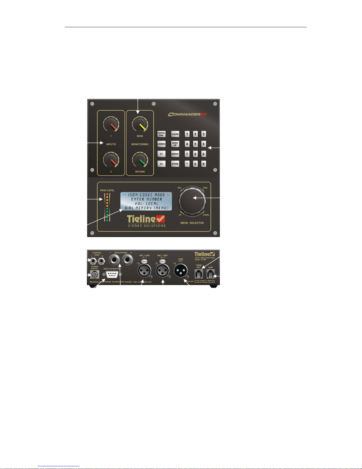
CONTROLS & CONNECTIONS
Field Unit TLF200
Menu Selector:
Rotate to scan Items
Click down to select item.
Visual
Output
LCD
Serial data
port for
connection to
a computer
and data
transmission
Keypad for Data Entry.
Function Keys,CLR
Hang Up etc.
Power
Supply
Software
controlled audio
input pots.
Software controlled send &
r
etu
rn
audio adjustme
nt POT
S
Headphone
monitoring
Balanced
mic/line
input 1
Balanced output
External Phone
Telephone Line
Peak
Program
Meter
Balanced
mic/line
input 2
2 CMOS relay
ports with
local or
remote control
operation

COMMANDER CONTROLS & CONNECTIONS
Rack Unit TLR200
Headphone
monitoring
Menu Selector:
Rotate to scan Items
Click down to select
item.
Visual
Output
LCD
Keypad for Data Entry.
Function Keys,CLR
Hang Up etc.
Software
controlled audio
input pots
Software
controlled
send &
return audio
adjustment
POTS
ISDN Line
(Optional)
Balanced
output
External Phone
Telephone Line
Peak
Program
Meter
Relay Control
Interface
(
Optional
)
Balanced
mic/line
input 1
Serial data port for
connection to a
computer and data
transmission
Balanced
mic/line
input 2
Ancillary
Control
Ports

COMMANDER QUICK START GUIDE for the Beginner
©Tieline Technology - 10 - August 2002
QUICK START GUIDE for the Beginner
Plug the COMMANDER in and wait for about 20 seconds for the unit to start up and load
the operating software.
Operating the Menu Selector (MS)
The rotary Menu Selector (MS) (see Controls & Connections on page 8) is used to operate
and configure the COMMANDER.
• Rotate the MS to scroll up, down or sideways on lists. The lists are viewable on the
LCD screen.
• Click the MS downwards to select an item in the LCD Screen which is highlighted in
[brackets].
NOTE the Keypad key marked CLEAR takes you back to the previous screen!
Setup for Microphone Input
Here is an example of how to use the MS in conjunction with the LCD screen to set up for a
microphone input;
1. Attach your Audio inputs to the XLR connector.
2. Attach a standard phone cord to RJ11 connector on the rear of your codec.
3. Use the MENU selector to change the Input to Microphone as follows;
Main screen – appears after start up
Select a Menu item by rotating the MS.
The selected item is identified by a square
bracket: [ ]. In this case you have a
choice of DIAL, MEMORY or MENU.
Choose MENU.
Scroll Down and select 05 Unit Setup.
Continues on next page…
Setup Menu
[05 Unit Setup ]
06 isdn Setuo
07 Advanced Setup
– POTS MODE –
Enter Number:
Ctl : Local
[DIAL] MEMORY MENU
– POTS MODE –
Enter Number:
Ctl : Local
[DIAL] MEMORY MENU

COMMANDER QUICK START GUIDE for the Beginner
©Tieline Technology - 11 - August 2002
…Continues from previous page
Select 01 Set Input Gain.
On Input 1 Scroll to High Gain Mic and
Select.
Repeat for Input 2.
You can select Continue or Exit.
You have now changed the Input type.
4. Set Input 1 and 2 knobs to 2 ‘o’clock position. This sets the outgoing program level.
5. To hear outgoing
audio through the headphones (plug into rear socket) set the Send
knob to 3 ‘o’ clock and Return knob to minimum. To hear return
audio from the other
end - reverse the Send and Receive knob settings.
6. You are now SET to GO!
7. Repeat steps 2,4 & 6 for the “Destination” Tieline Codec equipment.
8. You can monitor the output using headphones attached to this COMMANDER.
Alternatively, connect the audio program output as desired on the destination
COMMANDER.
Note: the Return knob on the destination equipment is the headphone volume. It
does not adjust the program output level.
9. Using the keypad, enter the telephone number of the destination codec and press the
Enter/Dial key.
Important: Ensure you have installed your unit correctly as instructed in the Installation
and Usage Tips section on page 7.
Unit Setup
[01 Set Input Gain ]
02 PPM Mode
03 Relay Operation
Set Input Gain
INP1 : [ Line Level ]
INP2 : Line Level
Changes Saved…..
Continue Setup?
[CONTINUE] EXIT

COMMANDER GETTING STARTED
©Tieline Technology - 12 - August 2002
GETTING STARTED
Setting Factory Defaults
Restoring to factory default settings is good practice. It gives your COMMANDER a configuration
with a predictable set of options.
FROM THE STARTUP SCREEN HERE’S HOW:
Rotate MS to
select MENU then Click MS.
Scroll using MS to [09 Reset Functions]
Select [09 Reset Functions] Click MS.
Scroll using MS
to [02 Reset Settings]
Select [02 Reset Settings] by clicking MS.
Continued on next page…
Setup Menu
[01 View Config ]
02 Codec Setup
03 Modem Setup
Setup Menu
[09 Reset Functions]
10 Test Modes
11 Memory Setup
Reset Functions
[01 Reset DSP ]
02 Reset Settings
03 Reset Phone Mem
Reset Functions
[02 Reset Settings ]
03 Reset Phone Mem
04 reset Funct Mem
– POTS MODE –
Enter Number:
Ctl : Local
[DIAL] MEMORY MENU
– POTS MODE –
Enter Number:
Ctl : Local IGC:--
[DIAL] MEMORY MENU
COMMANDER GETTING STARTED
©Tieline Technology - 13 - August 2002
…Continued from previous page
Scroll right to [RESET] Then select with
MS
Select [CONTINUE] and follow prompts to
[04 Reset Function Mem].
This restores default values to the F1 and
F2 keys.
On the Reset Funct Mem screen “All
Function Saved will be lost!!!!” warning is
given. Scroll using MS to select [RESET].
The last display is the same as above.
Select by scrolling the MS [EXIT] then
select by clicking the MS.
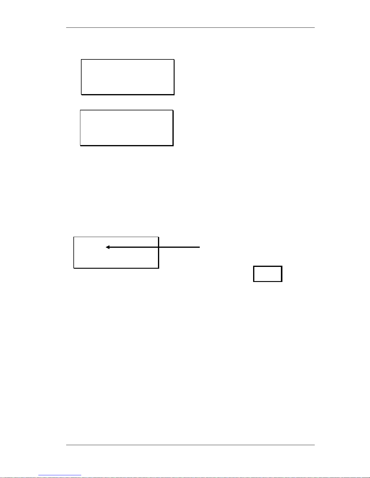
Dialing a number
Here’s how to make a connection from one COMMANDER to another using a standard Plane Old
Telephone Service (POTS) telephone line. Connect the telephone line to the modular socket at
the rear of the COMMANDER. Switch on and wait for the self-check functions to complete.
The COMMANDER will dial the number to establish a connection with the remote TIELINE Codec
equipment at an initial attempt of 19,200 bps bit-rate. The modems measure the characteristics of
the telephone line and then negotiate the highest possible stable data rate for best sound quality.
Dialing From an Office or Hotel Room
Most hotels and offices require dialing an additional digit(s) followed by a pause to gain access to
an outside line. After entering the access number, hold the “#” key until a comma (“,”) appears
after the access number on the LCD display. Now enter the rest of the telephone number. A two
second pause has now been inserted after the access digit to allow time for the outside line to be
set up for dialing. The length of this pause can be changed in the “View Config” menu.
Reset Settings
All Current Settings
Will be lost !!!!
[CANCEL] RESET
-POTS CODEC MODE-
92496688
Ctl :Local
[DIAL] H-SET
Enter the telephone number of
remote TieLine using the
keypad. The number appears
here.
Then Press
Changes Saved.....
Continue Setup?
[CONTINUE] EXIT
ENTER
DIAL
COMMANDER GETTING STARTED
©Tieline Technology - 14 - August 2002
Handset Dialing
An external telephone handset can be used to dial a number. This may be necessary if unusual
telephone system conditions cause problems with the COMMANDER dialer. Connect a telephone
to the “Handset” modular connector on the rear panel of the COMMANDER. Using the MS
scroll
to [DIAL] then click MS to select. Then follow the steps below;
* If the remote TIELINE Codec used a handset to answer the call, the remote TIELINE Codec user
must press the ANSWER key in order to connect with the modem.
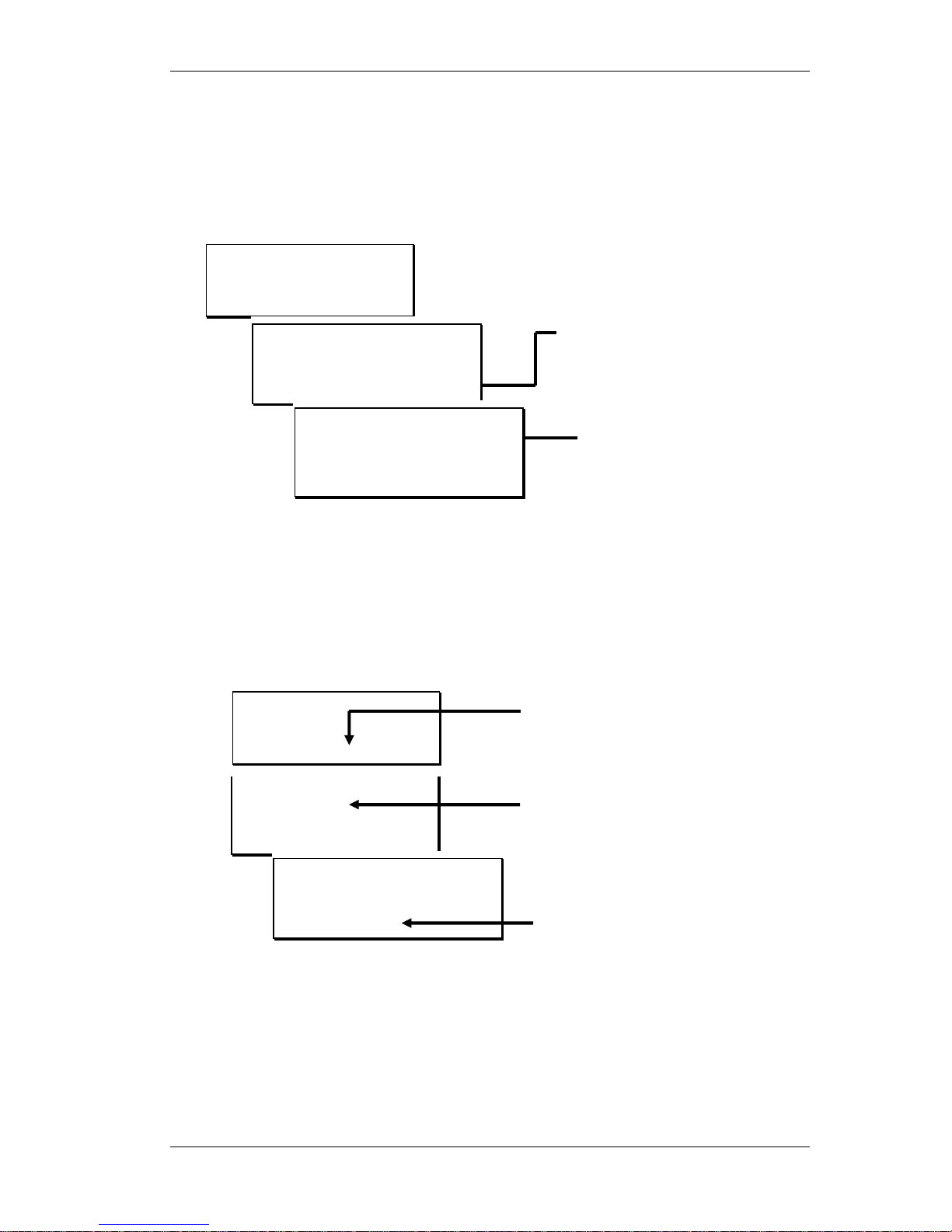
Dialing from Phone Book Memory
Commonly called numbers can be stored in COMMANDER’S internal phone book.
To dial a number from the phone book follow the sequence shown below:
Memory Dialing from Interstate or International call areas
When dialing frequently to a different area code or country, enter the area code or international
access codes into the PREFIX memory location. Enable the “Prefix” option in the “Setup” menu.
Using a prefix avoids the need to manually enter these codes each time a phone memory is used.
Only one Prefix memory is available
(see page 8 under Prefix Enable for more details).
Memory Selection
[01 Tieline Test]
02 Main Studio
03 Production Studio
- POTS MODE 92496688
Ctl :Local
[DIAL] H-SET
MS scroll to [Memory]
and click MS.
Scroll through the list to
choose a number.
Clicking the Menu
Selector enters the
number in the dialing
window
Press the “Enter/Dial key”
(or click Menu selector) to
start dialing.
MS Select [H-SET] and dial
the number on the phone
When the called TieLine Codec
answers; immediately press
“Enter” on the keypad & hang-up
the handset*
– POTS MODE –
Enter Number:
Ctl : Local
[DIAL] MEMORY MENU
-POTS MODE 92496688
Ctl: Local
DIAL [H-SET]
Modem Init…
Dial External Phone,
quickly hit ENTER &
hang-up. (See Manual)
CLEAR to EXIT
– POTS MODE –
Enter Number:
Ctl : Local
[DIAL] MEMORY MENU
COMMANDER GETTING STARTED
©Tieline Technology - 15 - August 2002
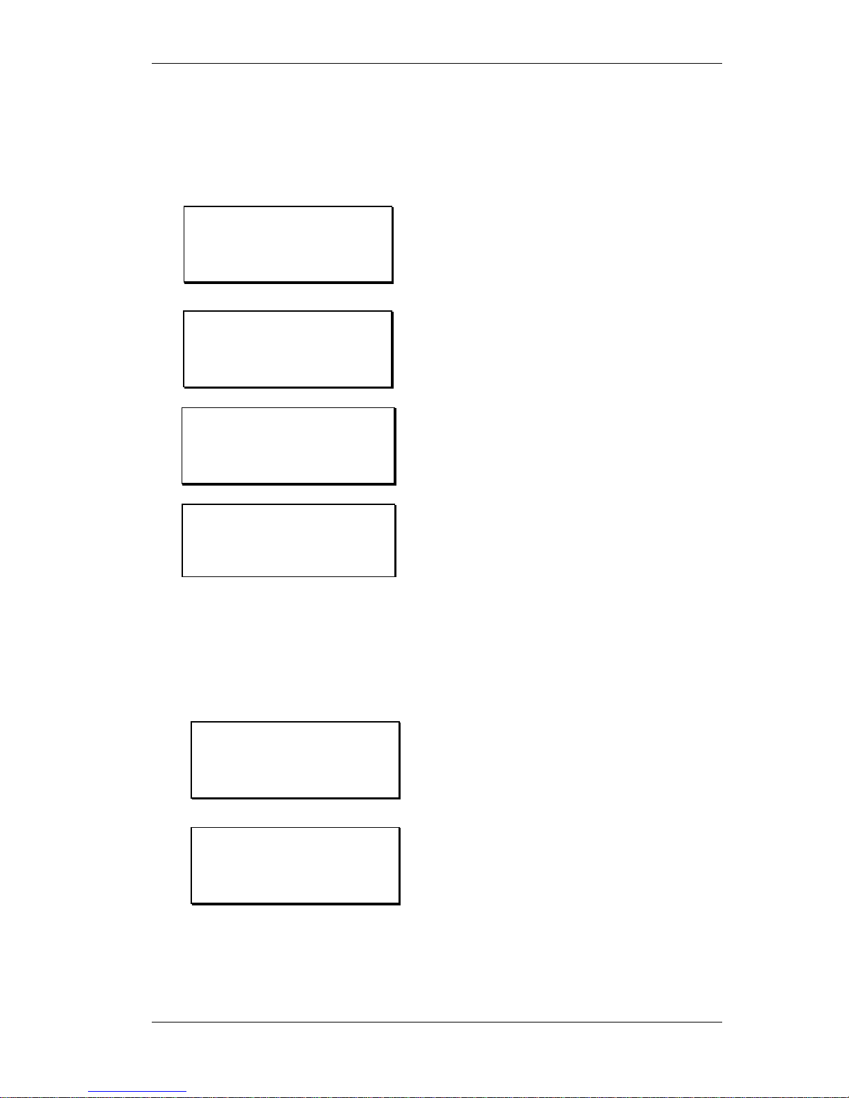
How to store a phone number
The COMMANDER can store up to 50 telephone numbers. The steps to save a number into
memory are set out below.
Quick Store
Main screen – appears after start up.
Select [DIAL].
Type in the phone number using the Key
Pad and press the Store button on the Key
Pad.
Enter the memory number (between 1 and
50), putting a zero before a single digit (ie
01 or 09).
The above procedure saves the number with the name of QUICK-STORE. To edit this name or
the telephone number refer to the next procedure.
Storing and naming a number and/or editing a stored number
Main screen – appears after start up
Select [MENU].
Continued on next page…
- POTS MODE -
Ctl: Local
[DIAL] H-SET
Memory Store
0812341234
Enter Location:
– POTS MODE –
Enter Number:
Ctl : Local
[DIAL] MEMORY MENU
– POTS MODE –
Enter Number:
Ctl : Local
[DIAL] MEMORY MENU
– POTS MODE –
Enter Number:
Ctl : Local
[DIAL] MEMORY MENU
– POTS MODE –
Enter Number:
Ctl : Local
[DIAL] MEMORY MENU
COMMANDER GETTING STARTED
©Tieline Technology - 16 - August 2002
…Continued from previous page
Select [11 Memory Setup].
Select either a new number or an existing
one to make changes to it.
If no change is required to the number then
select [OK] with the MS.
To change the number select [CLR] and
use the Key Pad to enter the new number.
Then select [OK] with the MS.
If no change is required to the name select
[OK] with the MS.
To change the name select [EDIT] with the
MS.
The letter being edited is surrounded by
brackets. In the example on the left the [Q]
is ready for editing. To change turn the MS,
select by clicking the MS.
Note that a space and other symbols are
found at the end of the alphabet, numbers
are at the beginning.
Press CLEAR on the Key Pad to complete
the changes.
Select [OK] to save the changes to memory.
Setup Menu
[11 Memory Setup ]
12 Unit Details
13 Exit Setup
Memory Setup
[01 QUICK-STORE ]
02 Main
03
Modem Setup
01: Edit Number
0812341234
[CLR] COPY PASTE OK
Modem Setup
01: Edit Name
QUICK STORE
[EDIT] CLEAR OK
01 [Q]UICK-STORE
0812341234
Press CLEAR to End.
01 Head Offic[e]
0812341234
Press CLEAR to End.
Modem Setup
01: Edit Name
Head Office
EDIT CLEAR [OK]
Hint: Copy
or Paste a
number
from one
location to
another
 Loading...